Claas Dominator 130 68 S (156) Combines Technical System ES
$300.00
- Model: Dominator 130 68 S (156) Combines
- Type Of Manual: Technical System
- Language: ES
- Format: PDF(s)
- Size: 11.0 MB
File List:
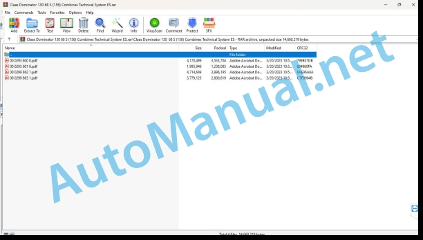
00 0293 600 0.pdf
00 0293 601 0.pdf
00 0299 862 1.pdf
00 0299 863 1.pdf
00 0293 600 0.pdf:
Technical systems DOMINATOR 130 hydraulic installation
1_x000B__x000B_Global hydraulic installation
1.1_x000B__x000B_Hydraulic installation in general
1.1.1 Hydraulic pumps
1.1.2 Oil filter head
1.2 Connection diagram of the global hydraulic system
1.2.1 Connection diagram of the overall hydraulic system – machine with grain tank
1.2.2 Connection diagram of the global hydraulic system – machine with bagging platform
2 Hydraulic steering installation / 3D control
2.1 Connection diagram of the hydraulic steering installation without AUTOPILOT
2.2 Connection diagram of the hydraulic steering system with AUTOPILOT
2.3 Steering valve unit
2.4 Steering function
2.5 Address Check
2.6 SELF-PILOT electromagnetic valve
2.7 Checking the AUTOPILOT system
2.8 3D controller
3_x000B__x000B_Operations hydraulic system
3.1 Connection diagram of the operating hydraulic system – machine with grain tank
3.2 Pressure limiting valve
3.2.1 Pressure limiting valve (703) – machine with grain tank
3.2.2 Pressure limiting valve – machine with bagging platform
3.3 Rotate the grain tank discharge tube
4/3 way valve
Hydraulic cylinder
3.4 Block valve block
3.5 Flow divider (optional) – with horizontal regulation of the reel
3.6 Reverse the direction of travel of the head
3/2 way valve (Y86)
Hydraulic cylinder
3.7 Horizontal adjustment of the reel
4/3 way valve
Hydraulic cylinder
3.8 Raise/lower the header, speed variator, vertical adjustment of the reel, variator of the shelling cylinder
6/9-way multifunctional valve
Hydraulic cylinder, vertical adjustment of the reel
Hydraulic cylinder, speed variator, sheller cylinder variator
Rotary connection and throttle check valve
3.9 Foot valve, speed variator
4_x000B__x000B_Location of components
Component Grid
Alphabetical index
0293 600.0
00 0293 601 0.pdf:
Technical systems Electrical installation DOMINATOR 130
Connection diagram configuration
central electrical system
Module occupancy
Module A12-1 – Speed Controller (DZW)
Module A12-2 – Speed Controller (DZW)
Module A12-3 – Speed Controller (DZW)
Module A15 – CATERPILLAR electronic engine regulation (CAT)
Connection diagrams 01a – 40a
01a Main voltage supply, diesel engine starter motor
02a Start the diesel engine and check the engine
03a Operational control of the diesel engine
12a Control of grain passage
13a Reverse whistle
17a Drive of the head, reversing the direction of travel
25a Speed control
26a Functional control of the machine
28a AUTOPILOT – (connection possibilities)
30a Omnidirectional flashing light – (connection options)
31a Flashing lights, alarm flashing lights
32a Main lighting switching, parking lights
34a Work lights, instrument lighting
35a Brake lights
37a Windshield wconditioning equipment
40a Additional sockets (cs)
Component Grid
Alphabetical index
0293 601.0
00 0299 862 1.pdf:
Technical systems – Hydraulic installation, Dominator 48 – 68, DO 48 from no. 15403117, DO 68 from no. 15608462
1 Global hydraulic installation
1.1 Hydraulic installation in general
Hydraulic bombs
Oil pressure
Type of oil
Oil change
Filling quantity
oil filter head
Oil filter
1.2 Connection diagram of the global hydraulic system
1.2.2 Connection diagram of the global hydraulic system – with straw gatherer
pressure measurement
1.2.1 Connection diagram of the overall hydraulic system – without straw gatherer
pressure measurement
2 Hydraulic steering installation / 3D control
2.1 Connection diagram of the hydraulic steering installation without AUTOPILOT
2.2 Connection diagram of the hydraulic steering system with AUTOPILOT
2.3 Steering valnit
2.4 Neutral steering function
Use of address
2.5 ess Check
2.6 SELF-PILOT electromagnetic valve
2.7 Checking the AUTOPILOT system
2.8 3D controller
3 Hydraulic operating system
3.1 Connection diagram of the hydraulic system for operations without straw gatherer
3.2 Pressure limiting valve
3.2.1 Pressure limiting valve (703) – with hydraulic swing grain tank discharge pipe
3.2.2 Pressure limiting valve – without hydraulic swing grain tank discharge pipe
3.3 Rotate the grain tank discharge tube
4/3 way valve
Hydraulic cylinder
3.4 Block valve block
3.5 Flow divider (optional) – with horizontal regulation of the reel or, where appropriate, straw gatherer
3.6 Cutting height automation (optional)
3/3 way electromagnetic valve
3.7 Horizontal adjustment of the reel
4/3 way valve
Hydraulic cylinder
3.8 Raise/lower the header, speed variator, vertical adjustment of the reel, variator of the shelling cylinder
6/9-way multifunctional valve
Hydraulic cylinder, vertical adjustment of the reel
Hydraulic cylinder, speed variator, sheller cylinder variator
Rotary connection and throttle check valve
3.9 Foot valve, speed variator
3.10 Straw gatherer
3/3 way valve
Location of components
Alphabetical index
0299 862.1
00 0299 863 1.pdf:
Technical systems – Electrical installation – Dominator 48 – 68, DO 48 from n° 15403117, DO 68 from n° 15608462
Electric system
Module occupancy
Module A12-1 – Speed Controller (DZW)
Module A12-2 – Speed Controller (DZW)
Module A12-3 – Speed controller (DZW)
Module A15 – CATERPILLAR electronic engine regulation (CAT)
01a Main power supply, diesel engine starter motor – with mechanical engine regulation
01b Main power supply, diesel engine starter – with electronic engine regulation (CAT)
02a Starting the diesel engine and engine control – with mechanical engine rarting the diesel engine and engine control – with electronic engine rega Diesel engine operational control – with mechanical engine control
03b Diesel engine operational control – with electronic engine control (CAT)
12a Control of grain passage
13a Straw collector – with mechanical motor regulation
13b Straw collector – with electronic motor regulation (CAT)
17a Drive of the head, reversing the direction of travel
25a Speed control
26a Functional control of the machine
28a AUTOPILOT – (connection possibilities)
30a Omnidirectional flashing light – (connection options)
31a Flashing lights, alarm flashing lights
32a Main lighting switching, parking lights
34a Work lights, instrument lighting
35a Brake lights
37a Windshield wipers
38a Air conditioning unit – with mechanical engine regulation
38b Air conditioning system – with electronic engine regulation (CAT)
40a Additional sockets (connection possible)
Component Grid
Alphabetical index
John Deere Parts Catalog PDF
John Deere Tractors 7500 Parts Catalog CPCQ26568 30 Jan 02 Portuguese
John Deere Repair Technical Manual PDF
John Deere Parts Catalog PDF
John Deere Tractors 6300, 6500, and 6600 Parts Catalog CQ26564 (29SET05) Portuguese
John Deere Repair Technical Manual PDF
John Deere Repair Technical Manual PDF
John Deere Repair Technical Manual PDF
John Deere Parts Catalog PDF
John Deere Harvesters 8500 and 8700 Parts Catalog CPCQ24910 Spanish
John Deere Repair Technical Manual PDF
John Deere POWERTECH E 4.5 and 6.8 L Diesel Engines TECHNICAL MANUAL 25JAN08
John Deere Repair Technical Manual PDF
John Deere 16, 18, 20 and 24HP Onan Engines Component Technical Manual CTM2 (19APR90)
John Deere Repair Technical Manual PDF

