Claas Dominator 150 140 (200) Combines Operator Manual ES
$50.00
- Model: Dominator 150 140 (200) Combines
- Type Of Manual: Operator Manual
- Language: ES
- Format: PDF(s)
- Size: 19.1 MB
File List:
00 0293 212 2.pdf
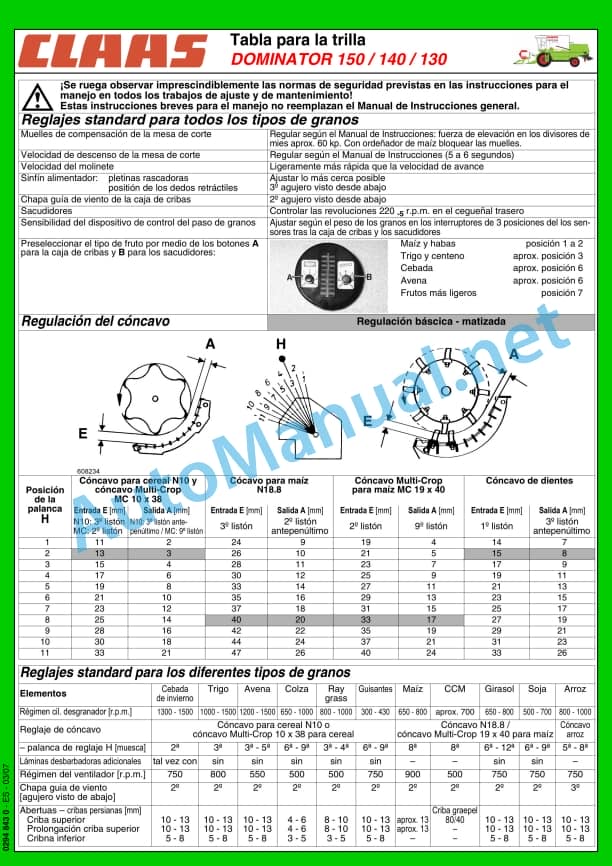
00 0294 843 0.pdf
00 0293 212 2.pdf:
1. Introduction
1.1 General instructions
1.1.1 Using the instructions
1.1.2 Validity of the manual
1.1.3 Technical data
1.1.4 Road traffic
1.1.5 Note regarding electronic engine management
1.2 Assembled parts/machine casing
1.2.1 Spare parts and technical issues
1.2.2 Machine identification plate
1.2.3 CATERPILLAR 3056 E engine identification plate
1.2.4 PERKINS 1006-6T engine identification plate
1.2.5 CATERPILLAR C6.6 engine identification plate
1.2.6 Drive axle identification plate
1.2.7 Steering axle identification plate
1.2.8 Hitch mouth identification plate
1.2.9 Hitch block identification plate
1.2.10 Cab identification plate
1.2.11 Straw chopper identification plate
2 Overall view of the machine
2.1 Assembled parts/machine casing
2.1.1 Machine summary
2.1.2 Access to the workplace and maintenance stations
3 Security measures
3.1 General instructions
3.1.1 General instructions
3.1.2 Especially important
3.1.3 Proper use of the machine
3.1.4 Predictably foolish misuse
3.1.5 Prescriptions for safety and accident prevention
3.1.6 Prescriptions for safety and prevention of accidents with harvesters
3.1.7 Before start-up, general instructions
3.1.8 Additional weights
3.1.9 Carry additional passengers
3.1.10 General driving
3.1.11 Combine driving operation
3.1.12 Driving on inclined terrain
3.1.13 Getting off the machine
3.1.14 Headers and trailers
3.1.15 Deposit the material / deposit the straw
3.1.16 Grain collection
3.1.17 Air conditioning installation
3.1.18 Adjustment and maintenance work
3.1.19 Pressure accumulator
3.1.20 Antifreeze
3.1.21 First aid measures
3.1.22 Decommissioning and waste disposal
3.1.23 Insert the feed channel safety support
3.1.24 Remove the safety support from the feed channel
3.1.25 Secure the machine with a chock so that it cannot roll
3.1.26 Hook the straw guide bib high
3.1.27 Raise the machine on blocks
3.1.28 Fire extinguisher
3.1.29 Battery separator switch
3.1.30 Risk of accident due to hydraulic fluid
3.1.31 Load and tie down the machine
3.1.32 Unscrew the hook rings
3.2 Safety instructions
3.2.1 Warning and danger signs
3.3 Warning symbols
3.3.1 General information on warning symbols
3.3.2 Engine
3.3.3 Undercarriage
3.3.4 Driver’s cab/platform
3.3.5 Power set
3.3.6 Threshing organs
3.3.7 Separation
3.3.8 Deposit the material / deposit the straw
3.3.9 Grain collection
3.3.10 Assembled parts/machine casing
3.4 Security stickers
3.4.1 General information regarding safety stickers
3.4.2 Undercarriage
4 Technical data
4.1 DOMINATOR 150 / 140 / 130
4.1.1 General instructions
4.1.2 CATERPILLAR C6.6 Engine
4.1.3 CATERPILLAR 3056E Engine
4.1.4 Perkins 1006-T6 Engine
4.1.5 Undercarriage
4.1.6 Chassis tire air pressure
4.1.7 Chassis track width
4.1.8 Brakes
4.1.9 Address
4.1.10 Electrical/electronic installation
4.1.11 Driver’s cabin/platform
4.1.12 Power Assembly
4.1.13 Threshing organs
4.1.14 Separation
4.1.15 Cleaning
4.1.16 Grain collection
4.1.17 Measurements of assembled parts / machine casing
4.1.18 Weights of assembled parts / machine casing
5 Before first start-up
5.1 General instructions
5.1.1 General warning instructions Before initial start-up
5.1.2 Checklist for first start-up
5.2 Undercarriage
5.2.1 Removing/installing the wheels
5.2.2 Steering axle summary
5.2.3 Adjusting the steering axle from the transport position to the working position
5.2.4 Steering axle 00 0649 950 1 – adjust track width
5.3 Hooking device
5.3.1 Installing the trailer coupling (additional equipment)
5.4 Electrical/electronic installation
5.4.1 Install the fan/air conditioning fuse
5.5 Power supply unit
5.5.1 Mount/adjust the support plates
5.5.2 Adjust the retention pins
5.5.3 Check the head cylinders
5.5.4 Check the head discharge springs
5.6 Grain collection
5.6.1 Close the cleaning flap on the grain tank discharge tube
5.6.2 Install the grain tank protection device
6 Before each start-up
6.1 General instructions
6.1.1 General warning instructions Before each start-up
6.1.2 Checklist for daily commissioning
7 Overview of control elements
7.1 General instructions
7.1.1 General warning information Overview of control elements
7.2 Driver’s cabin/platform
7.2.1 Overview of the driver’s position (DOMINATOR 130)
7.2.2 Overview of the driver’s position (DOMINATOR 150/140)
7.2.3 Hydraulic control (DOMINATOR 130 hydraulic lifting system)
7.2.4 Multifunctional control (DOMINATOR 150 / 140)
7.2.5 Control panel (DOMINATOR 130)
7.2.6 Diesel engine speed rotary switch (DOMINATOR 130, CATERPILLAR C-6.6, 3056 E)
7.2.7 Diesel engine speed lever (DOMINATOR 130, Perkins 1006-T6)
7.2.8 Function of warning lights 7 and 8 (DOMINATOR 130)
7.2.9 Control panel (DOMINATOR 150 / 140)
7.2.10 Diesel engine speed rotary switch (DOMINATOR 150 / 140)
7.2.11 Function of warning lights 15 and 18 (DOMINATOR 150 / 140)
7.2.12 Tie Rod Summary
7.2.13 Cab roof control elements
7.2.14 Cabin with fan
7.2.15 Cabin with air conditioning equipment (with York compressor)
7.2.16 Cabin with air conditioning equipment (with Sanden compressor)
7.2.17 Cabin with fan and heating
7.2.18 Control levers
7.2.19 Device for monitoring operation
7.3 Assembled parts / machine housing
7.3.1 Work focuses
7.3.2 Cabin
7.3.3 Awning
7.3.4 Tool box
8 Mount/dismount the front implement
8.1 General instructions
8.1.1 General warning instructions Mounting/dismounting the head
8.2 Assemble the head
8.2.1 Hang front implement
8.2.2 Lock front implement
8.2.3 Assemble cardan shaft
8.2.4 Connect the hydraulic system
8.2.5 Plug in the electrical installation (additional equipment)
8.2.6 Remove the support legs
8.3 Disassemble the head
8.3.1 Assemble the support legs
8.3.2 Uncouple the hydraulic system
8.3.3 Unplug the electrical installation (additional equipment)
8.3.4 Disassemble cardan shaft
8.3.5 Unlock front implement
8.3.6 Unhook front implement
9 Driving and transporting
9.1 General instructions
9.1.1 General warning instructions Driving and transporting
9.1.2 Prepare road traffic
9.1.3 Prepare field circulation
9.2 Engine
9.2.1 Adjusting the diesel engine speed (DOMINATOR 150 / 140)
9.2.2 Starting the diesel engine (DOMINATOR 150 / 140)
9.2.3 Disconnect the diesel engine (DOMINATOR 150 / 140)
9.2.4 Adjusting the speed of the diesel engine (DOMINATOR 130)
9.2.5 Starting the diesel engine (DOMINATOR 130)
9.2.6 Disconnect the diesel engine (DOMINATOR 130)
9.3 Running gear
9.3.1 Gear lever (DOMINATOR 150 / 140)
9.3.2 Shifting into gear (DOMINATOR 150 / 140)
9.3.3 Gear lever (DOMINATOR 130)
9.3.4 Shifting into gear (DOMINATOR 130)
9.3.5 Adjusting the control resistance of the drive lever (DOMINATOR 150 / 140)
9.3.6 Running characteristics
9.3.7 Towing the machine
9.3.8 Towing in front
9.3.9 Towing from behind
9.4 Brakes
9.4.1 Connect the parking brake
9.4.2 Disengage the parking brake
9.4.3 Foot brake
9.4.4 Brake / stop the machine (DOMINATOR 150 / 140)
9.4.5 Brake / stop the machine (DOMINATOR 130)
9.4.6 Parking the machine
9.5 Address
9.5.1 Steer the machine
9.5.2 Adapt the position of the steering bar
9.6 Hooking device
9.6.1 Hitching the trailer
9.6.2 Uncoupling the trailer
9.7 Driver’s cabin/platform
9.7.1 Adjusting the mechanically cushioned driver’s seat (standard equipment)
9.7.2 Adjusting the mechanically cushioned driver’s seat (standard equipment)
9.7.3 Adjusting the driver’s seat with mechanical damping (optional equipment)
9.8 Assembled parts / machine housing
9.8.1 Rotate the front ladder (standard)
9.8.2 Change the position of the rear ladder
10 Setting in operational mode
10.1 General instructions
10.1.1 General warning instructions Field work settings
10.2 Power unit
10.2.1 Adjust the cutting height indicator
10.2.2 Adjust the drainer profiles
10.2.3 Adjust the height of the feed chain
10.2.4 Adjusting the head lowering speed (DOMINATOR 150)
10.3 Threshing organs
10.3.1 Dismantle / assemble the concave segments (multicrop concave)
10.3.2 Adjust the basic concave setting
10.4 Separation
10.4.1 Adjust the separation grain passage control sensors
10.5 Cleaning
10.5.1 Check/adjust the fan speed indicator
10.5.2 Adjust the cleaning grain passage control sensors
10.5.3 Dismantle the sieves
10.5.4 Assemble the screens
10.6 Depositing the material / depositing the straw
10.6.1 Dismantle the straw guide plate (straw chopper with standard distributor)
10.6.2 Assemble the straw guide plate (straw chopper with standard distributor)
10.6.3 Unscrew the chopper blades
10.6.4 Screw the chopper blades
10.6.5 Straw chopper sieve mounting position
10.7 Grain collection
10.7.1 Adjusting the grain tank full indicator DOMINATOR 150
11 Operational service
11.1 General instructions
11.1.1 General warning instructions Use at work
11.2 Structure and operation
11.2.1 Cutting mechanism
11.2.2 Threshing organs
11.2.3 Shakers
11.2.4 Cleaning
11.2.5 Shelling
11.3 Fundamental rules for threshing with a combine harvester
11.3.1 Please keep in mind when harvesting with the combine:
11.4 Head
11.4.1 Horizontal adjustment of the reel (mechanical)
11.4.2 Horizontal adjustment of the reel (hydraulic)
11.4.3 Adjust the reel rotation speed
11.5 Power supply unit
11.5.1 Read support pressure
11.5.2 Read cutting height
11.5.3 Reversing front implement/feed unit
11.5.4 Connect the head
11.5.5 Disconnect the head
11.6 Threshing organs
11.6.1 Connect and disconnect the threshing devices
11.6.2 Disconnect the threshing devices
11.6.3 Adjust the concave
11.6.4 Assemble/dismantle the sheller slats (supplementary equipment)
11.6.5 Unclog the shelling cylinder
11.6.6 Adjust the speed of the shelling cylinder
11.6.7 Reduced speed for the shelling cylinder (chain drive)
11.7 Separation
11.7.1 Adjust the canvas bib
11.7.2 Take into account the straw jam alarm behind the separation
11.7.3 Adjust the separation grain passage control indicator
11.7.4 Assembling/disassembling the cockscombs
11.8 Cleaning
11.8.1 Adjust the fan speed
11.8.2 Adjust the air guide plate
11.8.3 Manually adjust the sieves
11.8.4 Adjust the cleaning grain passage control indicator
11.9 Depositing the material / depositing the straw
11.9.1 Put the straw chopper to work (place the standard spreader in chopping position)
11.9.2 Put the straw chopper in rest position (place the standard spreader in row position)
11.9.3 Placing the standard distributor in the transport position, transport trailer
11.9.4 Adjusting the bed knife (standard straw chopper)
11.10 Grain collection
11.10.1 Control return
11.10.2 Open / close the grain tank lid
11.10.3 Remove / insert the grain tank discharge tube (DOMINATOR 150 / 140)
11.10.4 Remove/insert the grain tank discharge tube (DOMINATOR 130)
11.10.5 Connect/disconnect grain tank discharge
11.10.6 Remove / assemble the grain tank auger cover plates
11.10.7 Clean the machine for a fruit change
11.11 Sieve boards / threshing boards
11.11.1 Screen table
11.11.2 Threshing table
11.12 Shelling
11.12.1 Shelling strips
12 Failures and solutions
12.1 General instructions
12.1.1 General warning information Incident and solution
12.2 Driver’s cabin/platform
12.2.1 Central electrical system
12.2.2 Failures and solutions of the air conditioning installation
12.3 Head
12.3.1 Head
12.4 Power unit
12.4.1 Power unit incident and solution
12.5 Threshing organs
12.5.1 Incident threshing bodies and solution
12.5.2 Sheller cylinder
12.6 Separation
12.6.1 Separation Incident and solution
12.7 Cleaning
12.7.1 Cleaning Incident and solution
12.8 Depositing the material / depositing the straw
12.8.1 Harvest discharge / straw discharge Incident and solution
12.9 Grain collection
12.9.1 Grain collection Incident and solution
12.9.2 Assemble the safety screw for grain tank discharge
13 Maintenance
13.1 General instructions
13.1.1 General warning instructions Maintenance
13.2 General instructions
13.2.1 Front implement
13.2.2 Clean engine compartment and danger areas
13.2.3 Straps
13.2.4 Drives
13.2.5 Screws
13.2.6 Lubrication
13.2.7 Cleaning of lubricants
13.2.8 Brakes
13.2.9 Wheels / tires
13.2.10 Hydraulic system
13.2.11 Electrical installation
13.2.12 Air conditioning installation
13.2.13 Protective devices
13.2.14 Spare parts
13.2.15 Imbalance
13.2.16 Welding work on the combine
13.2.17 Putting the machine out of service
13.2.18 Cleaning surfaces with adhesives
13.2.19 Recommendations for the conservation of the combine during winter
13.2.20 Coolant liquid
13.3 Maintenance table
13.3.1 Maintenance intervals
13.4 Lubricant table
13.4.1 Lubricants
13.5 Engine
13.5.1 Summary of CATERPILLAR C-6.6 engines
13.5.2 Summary of CATERPILLAR 3056 E engines
13.5.3 Summary of PERKINS 1006-6T engines
13.5.4 Overview of the cooling unit
13.5.5 Clean the diesel engine environment
13.5.6 Evacuate fuel from the fuel tank
13.5.7 Refuel the machine
13.5.8 Clean the fuel tank filler filter
13.5.9 Open/close the fuel system stopcock
13.5.10 Bleed the fuel system
13.5.11 Clean the fuel pre-filter filter
13.5.12 Drain condensation water from the fuel prefilter (standard equipment)
13.5.13 Change the fuel prefilter (standard equipment)
13.5.14 Drain the condensation water from the fuel pre-filter (additional equipment)
13.5.15 Change the fuel prefilter (additional equipment)
13.5.16 Change the fuel filter CATERPILLAR C-6.6 / 3056 E
13.5.17 Change the PERKINS 1006-6T fuel filter
13.5.18 Check the diesel engine oil level
13.5.19 Change oil / oil filter in diesel engine
13.5.20 Adjust diesel engine valves
13.5.21 Check the coolant level of the water radiator
13.5.22 Check the coolant mixing ratio
13.5.23 Change the coolant of the water radiator
13.5.24 Drain the coolant from the water radiator
13.5.25 Fill the coolant in the water radiator
13.5.26 Clean the radiator screen
13.5.27 Clean the refrigerant unit
13.5.28 Change the coolant pipes
13.5.29 Clean/replace air filter with plastic casing of diesel engine
13.5.30 Change the safety cartridge of the air filter with plastic casing of the diesel engine
13.5.31 Clean the air intake filter
13.5.32 Change the air suction pipes
13.5.33 Retighten the air intake pipe clamps
13.6 Running gear
13.6.1 Wheels / tires
13.6.2 Check the tightening torque of the wheel nuts / wheel studs
13.6.3 Clean the gearbox, around the drive axle
13.6.4 Check the oil level of the DOMINATOR 150 / 140 reducers
13.6.5 Drain the oil from the DOMINATOR 150 / 140 reducers
13.6.6 Fill the oil in the DOMINATOR 150 / 140 reducers
13.6.7 Check the oil level of the DOMINATOR 130 reducers
13.6.8 Drain the oil from the DOMINATOR 130 reducers
13.6.9 Fill oil in the DOMINATOR 130 reducers
13.6.10 Check the oil level of the gearbox drive shaft
13.6.11 Drain the oil from the gearbox drive shaft
13.6.12 Fill gearbox drive shaft oil
13.6.13 Adjusting the clutch of the DOMINATOR 130 feed device
13.6.14 Adjust the short circuit valve DOMINATOR 130
13.7 Brakes
13.7.1 Check / top up the brake fluid level
13.7.2 Adjust the parking brake
13.7.3 Adjust the foot brake
13.8 Drive belts / drive chains
13.8.1 General warnings
13.8.2 Left drive diagram DOMINATOR 150 / 140 / 130
13.8.3 Right drive diagram DOMINATOR 150 / 140 / 130
13.8.4 Adjust the belt (R1)
13.8.5 Adjust the belt (R2)
13.8.6 Adjust the belt (R3)
13.8.7 Adjust the belt (R4)
13.8.8 Adjust the belt (R5)
13.8.9 Adjust the belt (R8)
13.8.10 Adjust the belt (R9)
13.8.11 Adjust the belt (R10)
13.8.12 Remove the belt (R7)
13.8.13 Install the belt (R7)
13.8.14 Adjust the belt (R12)
13.8.15 Adjust the belt (R13)
13.8.16 Remove the belt (R14)
13.8.17 Install the belt (R14)
13.8.18 Adjust the belt (R14)
13.8.19 Remove the belt (R42)
13.8.20 Install the belt (R42)
13.9 Hydraulic system
13.9.1 Check the oil level of the hydraulic system
13.9.2 Hydraulic system, change oil / oil filter / ventilation filter DOMINATOR 150 / 140
13.9.3 Hydraulic system, change oil / oil filter / ventilation filter DOMINATOR 130
13.10 Electrical/electronic installation
13.10.1 Check the battery acid level
13.11 Driver’s cabin/platform
13.11.1 Clean/change the cabin air filter
13.11.2 Clean the cabin circulation air filter
13.11.3 Clean the cabin roof assemblies
13.11.4 Putting the air conditioning into service
13.11.5 Measures to protect the air conditioning equipment when there are long inactive times DOMINATOR 130 with York compressor
13.11.6 Control the humidity saturation of the cooling agents of the air conditioning equipment
13.11.7 Change the refrigerant agent of the air conditioning unit
13.12 Power supply unit
13.12.1 Clean feed channel receptions
13.12.2 Adjust the feed chains
13.12.3 Adjust the feed chain friction clutch
13.12.4 Check the friction plates in the feed channel
13.13 Threshing organs
13.13.1 Clean the stone collection device
13.13.2 Clean the threshing components
13.14 Separation
13.14.1 Clean the shakers
13.14.2 Check the canvas bib
13.14.3 Clean the separation grain passage control sensor
13.15 Cleaning
13.15.1 Clean the cleaning grain passage control sensor
13.15.2 Clean the fan
13.15.3 Adjust the fan speed indicator
13.15.4 Clean stepped bottoms
13.15.5 Clean the sieves
13.16 Grain collection
13.16.1 Adjust the return elevator chain
13.16.2 Adjust grain elevator chain
13.16.3 Clean the auger trays
13.16.4 Clean the grain tank
13.16.5 Adjust the transportation position of the grain tank discharge tube support
13.17 Assembled parts / machine casing
13.17.1 Check the fire extinguisher
14 Greasing scheme
14.1 Grease points
14.1.1 General warning instructions Greasing scheme
14.1.2 Lubricants
14.1.3 Greasing intervals
14.1.4 Grease points – 10 h left
14.1.5 Greasing points – 10 h right.
14.1.6 Grease points – 50 h left
14.1.7 Grease points – 50 h right.
14.1.8 Grease points – 100 h left
14.1.9 Grease points – 100 h right.
14.1.10 Grease points – 500 h left
14.1.11 Grease points – 500 h right.
Alphabetical index
John Deere Repair Technical Manual PDF
John Deere Repair Technical Manual PDF
John Deere Repair Technical Manual PDF
John Deere Repair Technical Manual PDF
John Deere Diesel Engines POWERTECH 2.9 L Component Technical Manual CTM126 Spanish
John Deere Repair Technical Manual PDF
John Deere POWERTECH E 4.5 and 6.8 L Diesel Engines TECHNICAL MANUAL 25JAN08
John Deere Repair Technical Manual PDF
John Deere Repair Technical Manual PDF
John Deere Repair Technical Manual PDF
John Deere Repair Technical Manual PDF
John Deere Diesel Engines PowerTech 4.5L and 6.8L – Motor Base Technical Manual 07MAY08 Portuguese


