Claas Dominator 150 140 (200) Combines Technical System FR
$150.00
- Model: Dominator 150 140 (200) Combines
- Type Of Manual: Technical System
- Language: FR
- Format: PDF(s)
- Size: 8.9 MB
File List:
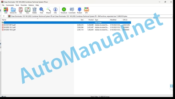
00 0187 997 0.pdf
00 0293 152 1.pdf
00 0293 158 2.pdf
00 0187 997 0.pdf:
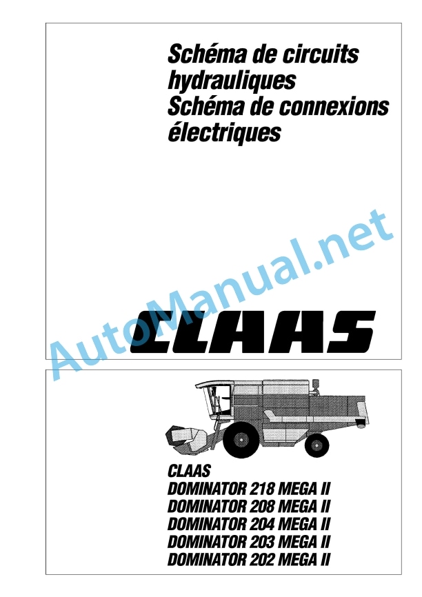
187997’0-HE-D0218-202MegaII-F-A3.pdf
00 0293 152 1.pdf:
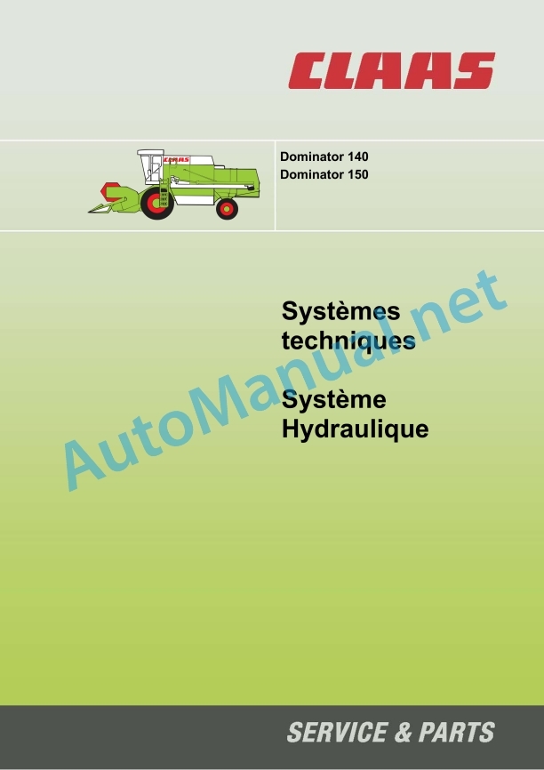
Dominator 140/150 Hydraulic System
Chapter 1_x000B_General hydraulics
1.1 Diagram of general hydraulic connections with 3D cleaning box
1.2 Diagram of general hydraulic connections without 3D cleaning box
1.3 Technical characteristics
Chapter 2_x000B_Hydraulic steering system
2.1 Diagram of hydraulic steering connections
2.3 Steering valve block
2.4 Function of management
2.5 Management check
Chapter 3_x000B_Hydraulic operating system
3.1 Diagram of operating hydraulic connections
3.2 Main valve
3.3 Adjusting the mixer rotation speed
3.4 Vertical adjustment of the reel
3.5 Horizontal adjustment of the reel
3.6 Pivoting the drain chute
3.7 Inversion of the front tool
Chapter 4_x000B_Hydraulic advancement system
4.1 Connection diagram of the LINDE hydraulic advancement system
4.2 Pump block
4.3 Servo control valve
4.4 Multifunction valve of the hydrostatic drive
4.5 Constant motor of hydrostatic drive
4.6 Maintenance
4.7 3D control
Component Locations
Component Locations
Alphabetical index
0293 152.1
00 0293 158 2.pdf:
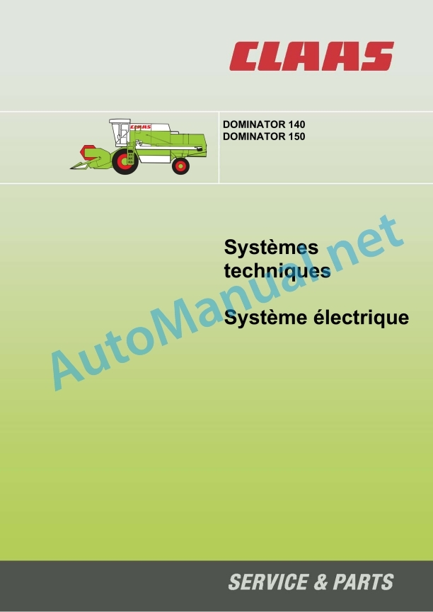
DOMINATOR 140/150 electrical system
Construction of electrical plans
Power plant
Module pinout
Module A12-1 – Safety of the shaker speed / return to the drums
Module A12-2 – Feeder/Elevator RPM Safety
Module A12-3 – Safety of the straw chopper regime
Module A15 – electronic control of the CATERPILLAR CAT-3056 engine
Module A15 – electronic engine control CATERPILLAR – C 6.6
Electrical plan 01a – 40a
01a Main voltage supply, diesel engine starter. with electronic motor adjustment CAT-3056
01b Main voltage supply, diesel engine starter. with electronic engine adjustment CAT C 6.6
02a Starting the diesel engine and controlling the engine. with electronic motor adjustment CAT-3056
02b Starting the diesel engine and controlling the engine. with electronic engine adjustment CAT C 6.6
03a CAT-3056 Diesel Engine Safety
03b Safety of the CAT C 6.6 diesel engine
04a Road driving control, circuit breaker valve
06a Terminal voltage supply / operating hours counter
08a Beater variator
12a Flow control
13a Straw collector / reverse buzzer
14a Pivoting the drain chute
17a Front tool drive, reverse drive
20a Raising / lowering the front tool
21a Adjusting the reel
22a Reel variator
25a Safety of the rotation regime
26a Machine safety
30a Grain hopper indicator / rotating beacon
31a Flashing, hazard lights
32a Main lighting control, positioning light
34a Working lighting, interior lighting, instrument lighting
35a Brake lights
37a Windshield wiper
38a Air conditioning
40a Auxiliary sockets (connection possibility)
Coordination diagram
0293 158.2
John Deere Repair Technical Manual PDF
John Deere Repair Technical Manual PDF
John Deere POWERTECH E 4.5 and 6.8 L Diesel Engines TECHNICAL MANUAL 25JAN08
John Deere Repair Technical Manual PDF
John Deere Transmission Control Unit Component Technical Manual CTM157 15JUL05
John Deere Repair Technical Manual PDF
John Deere Repair Technical Manual PDF
John Deere Repair Technical Manual PDF
John Deere Parts Catalog PDF
John Deere Harvesters 8500 and 8700 Parts Catalog CPCQ24910 Spanish
John Deere Repair Technical Manual PDF
John Deere Repair Technical Manual PDF


