Claas Dominator 260 (562) Combines Technical System EN
$300.00
- Model: Dominator 260 (562) Combines
- Type Of Manual: Technical System
- Language: EN
- Format: PDF(s)
- Size: 70.0 MB
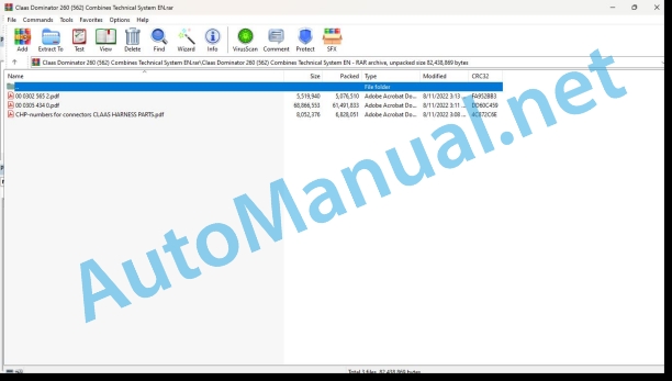
File List:
00 0302 565 2.pdf
00 0305 434 0.pdf
CHP-numbers for connectors CLAAS HARNESS PARTS.pdf
00 0302 565 2.pdf:
Sensor system
Table of contents
CCN explanation
CCN (CLAAS Component Number)
Electric system standard
Overview
Hydraulic system standard
Overview
CCN (CLAAS Component Number)
Introduction
Safety rules
Safety and hazard information
10 Electrical / Electronic equipment
1097 Testing / Measuring / Adjusting
Test report of the angle sensor (0011780.x)
Application of test report
Required tools
Test report of the angle sensor (0011780.x)
Testing / Measuring / Adjusting of angle sensor (0011780.x)
1. Reason for test
2. Mechanical test of angle sensor
3. Electric test with CDS
4. Electric test with multimeter
5. Mechanical test of connecting cable
Completing the machine
Test report of position and speed sensors
Application of test report
Required tools
Sensor variants
Part numbers of speed sensors
Part number of position sensor
Test report of position and speed sensors
Testing / measuring / adjusting of position and speed sensors
1. Reason for test
2. Mechanical test
3. Electric test with CDS
4a. Installation dimensions
Check of installation dimension
Installation dimensions of gearbox speed sensor (0011 799.x) and cam speed sensor (0011 810.x)
Installation dimension of position sensor (0011 815.x)
4b. Installation position
Centring of sensor
Metal-free zone
5. Electric test with multimeter
Voltage measurement
Direction of rotation and speed sensor (0011 605.x)
Measured values table
6. Mechanical test of connecting cable
Completing the machine
Test report of the urea sensor (00 0773 207 x)
Application of test report
Required tools
Parts number of the urea sensor
Test report of the urea sensor
Testing / measuring / adjusting urea sensor
1. Reason for test
2. Mechanical test
3. Mechanical test of connecting cable
4. Electric test with multimeter
5. Component test with the CDS
00 0305 434 0.pdf:
DOMINATOR 260
Table of contents
Introduction
Notes on the manual
Validity of manual
Information about this Technical Systems Manual
Using the manual
Document structure based on subassemblies
Search and find
Directions
Identifying warnings
Hazard signs
Signal word
Safety rules
Safety signs and warnings
Requirement made on technical staff
Children in danger
Hazard areas of the machine
Instructors travelling along during fieldwork
Risk of injury from rotating shafts
Structural alterations of the machine
Optional equipment and spare parts
Control of running machine
Technical condition
Respecting technical limit values
Danger from machine parts that continue rotating
Keeping safety devices functional
Personal protective equipment
Wearing suitable clothing
Removing dirt and loose objects
Parking the machine safely
Unsuitable operating utilities
Safe handling of service fluids and auxiliary utilities
Environmental protection and disposal
Keeping the cab free of chemicals
Avoiding fires
Potentially fatal electric shock from overhead lines and lightning strike
Electric shock from electric system
Noise may damage your health
Pre-loaded machine parts
Liquids under pressure
Compressed air
Toxic exhaust gases
Hot surfaces
Safe access and leaving
Working only on the stopped machine
Hazards during repairs
Raised machine parts and loads
Danger from welding work
Checking and charging the battery
Preparations for cases of emergency
CCN explanation
CCN (CLAAS Component Number)
Electric system standard
Overview
Hydraulic system standard
Overview
CCN (CLAAS Component Number)
01 Engine
0150 Engine attachment parts
Starting the diesel engine
Description of function
Perkins speed table
0155 Engine control
Diesel engine monitoring
Measured values table
Description of function
03 Chassis
0330 Rear steering drive axle
Description of function
0335 Ground drive
Hydrostatic ground drive
Description of function
Pump unit (HPV)
Description of function
Servo-control valve
Description of function
Multifunction valve (7013/7014)
Description of function
Ground drive fixed-displacement motor (HMF)
Description of function
05 Steering
0505 Steering
Steering system – General
Neutral function diagram
Function diagram with steering actuated
09 Hydraulic system
0910 Pumps
Ground drive variable-displacement pump
Key to diagram
0920 Valves
Main valve
Working hydraulics valve block
Front attachment dampening valve block
Steering (Orbitrol) valve block
Low-pressure hydraulics valve block
Reel drive valve block
Hydraulic system thermostat
0930 Cylinders
Hydraulic cylinder – variants of end position venting
Description of function
0980 Hydraulic circuit diagram
Machine circuit diagram
Front attachment hydraulics circuit diagrams
Cutterbar C370-C490 – reel adjustment
10 Electrical / Electronic equipment
1010 Central electrics
Basic central terminal compartment
Fuse assignment
Relay assignment
1012 Modules / sensors
Module A008 – AUTO CONTOUR (CAC)
Key to diagram
Module pin assignment A008 – AUTO CONTOUR (CAC)
Module A015 – engine control unit TIER3
Key to diagram
Module A015 – engine control unit TIER3
Module A069 – vehicle base module (VBM)
Key to diagram
Module assignment A069 – Vehicle base module (VBM)
Module A183 – vehicle base module 2 (VBM2)
Key to diagram
Key to diagram
Module A184 – vehicle base module 3 (VBM3)
Key to diagram
Key to diagram
1015 Wiring harnesses
FLEX wiring loom – type 318
FLEX wiring loom – type 319
1035 Operation / Multifunction control lever
T signal function
Measured values table
Description of function
Road travel – fieldwork circuit function
Description of function
1080 Electrical circuit diagram
Introduction into circuit diagrams
Overview of designations
CLAAS wire marking
Wire colours
Power supply
Actuators
Actual value switch (output = 0 or 1)
Internal connections
Overview of CAN bus system
Communication
Standards
Electric circuit diagrams of machine (SCM)
SCM 01 – Multicoupler
SCM 02 – Electric power supply – Starting the diesel engine
Key to diagram
SCM 03 – Power supply of modules
Key to diagram
SCM 04 – Road travel
Key to diagram
SCM 05 – Threshing mechanism
Key to diagram
SCM 06 – Power supply of sensors
Key to diagram
SCM 07 – Earth supply
SCM 08 – CAN0 (Vehicle CAN) / CAN1 (J1939-CAN)
Key to diagram
SCM 09 – CAN2 (Front CAN) / CAN5 (ISO Bus CAN)
Key to diagram
SCM 10 – Diesel engine speed adjustment – Diesel engine control unit
Key to diagram
SCM 11 – Diesel engine monitoring
Key to diagram
SCM 12 – Front clutch engagement – Front attachment reverse
Key to diagram
SCM 13 – Raise / lower front attachment – CAC
Key to diagram
SCM 15 – Reel speed adjustment
Key to diagram
SCM 16 – Reel adjustment
Key to diagram
SCM 19 – Circulation lock valve, hydraulic system monitoring
Key to diagram
SCM 20 – Speed monitoring
Key to diagram
SCM 21 – Threshing mechanism speed adjustment
Key to diagram
SCM 22 – Fan speed adjustment
Key to diagram
SCM 23 – Machine monitoring
Key to diagram
SCM 25 – Swinging the grain tank unloading tube in/out / grain tank unloading
Key to diagram
SCM 26 – Grain tank full indicator / warning beacons
Key to diagram
SCM 27 – Brake light
Key to diagram
SCM 28 – Back-up horn
Key to diagram
SCM 29 – Air conditioner
Key to diagram
SCM 30 – Windscreen wiper / windscreen washer system
Key to diagram
SCM 31 – Light / side lights main circuit
Key to diagram
SCM 32 – Drive lights
Key to diagram
SCM 33 – Main work light circuit
Key to diagram
SCM 34 – Grain tank work light / returns / sieve pan
Key to diagram
SCM 35 – Turn flasher light
Key to diagram
SCM 36 – Instrument lighting
Key to diagram
SCM 37 – Cab equipment
Key to diagram
SCM 38 – Service sockets
Key to diagram
SCM 40 – Overview of modules
Key to diagram
SCM 41 – Overview of connectors
Key to diagram
SCM 43 – Fuel pump
Key to diagram
SCM 46 – Indicator lights
Key to diagram
SCM 49- Diesel engine diagnostic plug
Key to diagram
SCM 51 – Engine control unit
1081 Overview of connectors
Connector database (chp CLAAS)
Example of representation of key numbers (CHP)
Connector representation (CHP)
1085 Networks
BUS systems (CAN) – Basic machine
Description of function
1097 Testing / Measuring / Adjusting
12 Cab / Operator’s platform
1230 Seat
Seat contact
Description of function
20 Crop feeding
2002 Front attachment
Raising / lowering the front attachment
Measured values table
Description of function
Front attachment ON / OFF
Description of function
Function not actuated (S055 in rest position)
Front attachment ON
Front attachment OFF
Important:
Reverse front attachment
Description of function
Front attachment dampening
Measured values table
Description of function
2015 Reel / Crop guard
Raise/lower reel
Reel adjustment function description
Reel speed adjustment
Reel adjustment function description
26 Ground guidance
2697 Testing / Measuring / Adjusting
Pressure accumulator adjustment
Accumulator pressure filling instructions
41 Threshing mechanism
4100 Threshing mechanism
Threshing mechanism ON/OFF
Description of function
4120 Threshing drum
Threshing drum speed adjustment
Measured values table
Description of function
43 Cleaning system
4325 Cleaning fan
Fan speed adjustment
Description of function
61 Grain delivery
6110 Grain tank
Grain tank fill indicator
Description of function
6120 Grain tank unloading
Grain tank unloading
Description of function
Swinging the grain tank unloading tube
Description of function
92 Diagnosis
9210 Error codes machine
FMI fault codes
FMI 00 (signal too high)
FMI 01 (signal too low)
FMI 02 (erratic signal)
FMI 03 (voltage too high)
FMI 04 (voltage too low)
FMI 05 (current too low)
FMI 06 (current too high)
FMI 07 (mechanical fault)
FMI 08 (faulty frequency signal)
FMI 09 (communication fault)
FMI 10 (signal change too fast)
FMI 11 (multiple faults)
FMI 12 (ECU defective)
FMI 13 (signal outside of calibration range)
FMI 16 (parameter not available)
FMI 17 (ECU does not respond)
FMI 18 (power supply fault)
FMI 19 (software conditions not met)
FMI 95 (no signal change)
FMI 96 (CAN BUS system defective)
FMI 97 (erratic status)
FMI 98 (warning)
FMI 99 (Info)
Machine fault code list (DTC)
DTC (Diagnostic Trouble Code) overview
Position of components
Hydraulic system
1000 Oil reservoir / oil filter / oil cooler
2000 Pump / motor
3000 Hydraulic cylinders
5000 Pressure accumulators
7000 Valves – hydraulically actuated
9000 Measuring points / gauges
Electric system
A Terminal / modules
B Sensors
C Electrical / electronic devices
E Lighting
G Voltage sources
H Signal device / light
K Relays
M Motor (electric)
S Switches / pushbuttons – cab operation
U Switches – External operation
Y Solenoid coils
Z Actual value switches
CHP-numbers for connectors CLAAS HARNESS PARTS.pdf:
CLAAS HARNESS PARTS
Table of contents
10 Electrical / Electronic equipment
1081 Overview of connectors
CLAAS HARNESS PARTS (CHP)
John Deere Repair Technical Manual PDF
John Deere Repair Technical Manual PDF
John Deere Diesel Engines PowerTech 4.5L and 6.8L – Motor Base Technical Manual 07MAY08 Portuguese
John Deere Repair Technical Manual PDF
John Deere Repair Technical Manual PDF
John Deere Repair Technical Manual PDF
John Deere Repair Technical Manual PDF
John Deere PowerTech M 10.5 L and 12.5 L Diesel Engines COMPONENT TECHNICAL MANUAL CTM100 10MAY11
John Deere Parts Catalog PDF
John Deere Harvesters 8500 and 8700 Parts Catalog CPCQ24910 Spanish
John Deere Repair Technical Manual PDF
John Deere Diesel Engines POWERTECH 2.9 L Component Technical Manual CTM126 Spanish


