Claas Dominator 76 (084) Combines Repair Manual EN
$300.00
- Model: Dominator 76 (084) Combines
- Type Of Manual: Repair Manual
- Language: EN
- Format: PDF(s)
- Size: 38.1 MB
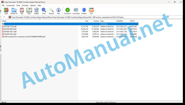
File List:
00 0184 778 0.pdf
00 0300 960 0.pdf
00 0302 343 1.pdf
00 0302 565 2.pdf
CHP-numbers for connectors CLAAS HARNESS PARTS.pdf
00 0300 960 0.pdf:
DOMINATOR 40 TERRA TRAC
Table of contents
Introduction
General information
Handling the manual
Texts and figures
Document structure based on the assembly structure
Search and find
Directions
Abbreviations
Technical terms
Validity of manual
General repair instructions
Technical specifications
Reason of damage
Spare parts
Alternator
Welding work
Drive belts / drive chains
Taper ring fasteners
Gib head key joints
Dismounting
Installation
Self-locking bolts
Liquid locking compound
Lock collar bearing
Dismounting
Installation
Adapter sleeve bearings
Dismounting
Installation
Ferrule fittings
Screwing in
Non-tight ferrule connection
Progressive ring fittings on hydraulic lines
Sealing cone fittings
Hydraulic hoses
Information on proper repairs
Torque settings
Tightening torques for metric standard threads
Tightening torques for metric fine thread screws
Tightening torques for hydraulic screw fittings with ferrule according to DIN 3861
Tightening torques for hydraulic screw fittings and air conditioner screw fittings with sealing cone and O-ring according to DIN 3865
Tightening torques for SDS hydraulic male connectors
Tightening torques for direction-adjustable SDE hydraulic male connectors
Tightening torques for hydraulic swivel fittings
Tightening torques for hollow screws DIN 7643
Tightening torques for worm drive hose clamps
Tightening torque for spring-loaded worm drive hose clamps
Technical specification
Lubricants
General information
Of special importance
Identification of warning and danger signs
General safety and accident prevention regulations
Combine-harvester safety and accident prevention regulations
Crop / straw discharge
Leaving the machine
Grain tank
Combine harvester chopper
Adjustment and maintenance operations
Risk of injury by hydraulic liquid
Hydraulic accumulators
First aid measures
Battery isolating switch
Apply the feeder housing safety lock
Jacking up the machine
Putting the machine out of operation
01 Engine
0102 Complete component
Diesel engine
Work preparation
Special tools
Removal of diesel engine
Removal of side flap
Tensioning device
Tensioner belt
Hydraulic hoses
Electric system
Starter relay
Alternator
EGR valve
Acclerator rod
Diesel pipe
Air pump
Air reservoir
Water separator
Torque fittings
Installation
Work Preparation:
Diesel engine:
Water separator
Air reservoir
Air pump
Diesel pipe
Accelerator rod:
Electric system
EGR valve
Alternator
Starter relay
Hydraulic hoses
Tensioner belt
Tensioning device
Finalization:
0125 Fuel system
Fuel tank
Work preparation
Special tool
Removal of fuel tank
Electric system
Fuel supply
Installation of fuel tank
Fuel supply
Electric system
Strap clamps
Finalization
0135 Cooling system
Cooling system
Work preparation
Removal of oil cooler
Air flow pipe
Radiator
Coolant reservoir
Covering
Note: Before removing the radiator:
Installation
Radiator
Covering
Air flow pipe
Coolant reservoir
Oil cooler
Finalization
0140 Exhaust system
Silencer
Work preparation
Removal of silencer
Installation of silencer
Finalization
0145 Air intake
Air intake
Removal of air intake:
Installation of air intake
Finalization
0150 Engine Attachment parts
Engine attachment parts
Before removal
Removal of engine attachment parts
Starter relay
Alternator
EGR valve
Installation engine attachment parts
EGR valve
Alternator
Starter relay
Finalization
02 Gearbox / Clutch / Universal drive shaft
0210 Oscillation damper
Complete gearbox:
Work preparation
Before removal
Removal of hydraulic gear box
Installation of Hydraulic gearbox
Finalization:
Engine output
Work preparation
Special tool
Removal of engine output pulley
Installation of engine output pulley
Removing the oscillation damper
Installation of oscillation damper
Finalization
03 Chassis
0355 Track roller unit
Crawler track unit
Work preparation
Special tool
Removal of rubber track
Guide wheel
Support wheel
Rubber track
Driving gear
Installation of rubber track:
Driving gear
Rubber track
Support wheel
Guide wheel
Finalization
08 Drives
0800 Drives
0808 Main drive
Engine output
Work preparation
Special tool
Work preparation
Removal of engine output pulley
Installation of engine output pulley
Finalization
Belt (R1)
Special tool
Special tool
Work preparation
Removal of Impeller drive:
Driven pulley:
Installation of Impeller drive
Driven pulley:
Finalization
0820 Front attachment drive
Chain (R4)
Special tool
Work preparation
Removal of the driven Sprocket:
Installation of the driven sprocket
Finalization
Chain (K7)
Work preparation
Removal of the Reel sprocket:
Installation of the reel sprocket
Finalization
Belt (R3)
Special tool
Work preparation
Removal of cutter bar drive
Drive pulley:
Installation of cutter bar drive
Drive pulley:
Finalization
0841Threshing drum drive
Belt (R10)
Work preparation
Before removal
Removal of threshing drum drive
Installation of threshing drum drive
Finalization
0821 Feeder unit drive
Belt (R2)
Special tool
Work preparation
Removal of feeder drive
Drive pulley:
Driven pulley:
Installation of feeder drive
Driven pulley:
Drive pulley:
Finalization
0842 Separation drive
Belt (R12)
Special tool
Work preparation
Removal of seperation drives:
Straw walker drive pulley:
Installation of separation drives
Straw walker drive pulley
Finalization
0860 Cleaning system drive
Belt (R11)
Work preparation
Before removal
Removal of cleaning system drive
Sieve box pulley
Fan pulley
Installation of cleaning system drive
Fan pulley
Sieve box pulley
Finalization
0861 Grain delivery drive
Chain (K13)
Work preparation
Removal of return elevator auger drive:
Drive sprocket:
Driven sprocket:
Installation of return elevator auger drive
Driven sprocket
Drive sprocket:
Finalization
Chain (K14)
Special tool
Work preparation
Removal of grain tank unloading drive
Drive sprocket:
Grain tank unloading sprocket:
Installation of grain tank unloading drive
Grain tank unloading sprocket
Drive sprocket:
Finalization
Belt (R12)
Special tool
Work preparation
Removal of clean grain auger drive
Grain auger drive pulley
Installation of clean grain auger drive
Grain auger drive pulley
Finalization
Belt (R9)
Special tool
Work preparation
Removal of return drive
Driven pulley:
Drive pulley:
Installation of return drive
Drive pulley
Driven pulley:
Finalization
09 Hydraulic system
0905 Hydraulic oil reservoir
0907 Hydraulic oil cooler
Hydraulic oil cooler
Work preparation
Removal of hydraulic oil cooler
Installation of hydraulic oil cooler
Finalization
0910 Pumps
Hydraulic pump:
Work preparation
Removal of hydraulic pump
Installation of hydraulic pump
Hydraulic hoses
Finalization
0920 Main valve
Main valve
Work preparation
Removal of main valve
Installation of main valve
Finalization
10 Electrical / Electronic equipment
1010 Central electrics
Central terminal compartment
Work preparation
Removal of Operating console
Installation of operating console
Finalization
1020 Driving lights
Driving lights:
Work preparation
Removal of driving lights(R2)
Installation of driving lights(R2)
Finalization
1025 Working lights
Working lights:
Work preparation
Removal of working light
Installation of working light
Finalization
1035 Operation / Multifunction lever
Control lever:
Work preparation
Removal of control lever
Installation of control lever
Removal of Battery
Installation of battery
Finalization
12 Cab / Operator’s platform
1215 Operator’s platform
Before removal
Removal of Sun roof
Installation of Sun roof
Operating console
Before removal
Removal of Operating console
Installation of operating console
Finalization:
1225 Mirror
Removal of mirror
Installation of mirror
1230 Seat
Removal of seat
Installation of seat
20 Crop feeding
2015 Cutter bar
Reel drive
Removal of reel drive
Work preparation:
Installation of reel drive
Removal of tine spring
Installation of tine spring
Finalization
21 Feeder unit
2110 Feed rake
Feeder Unit
Dominator 40 Terra Trac
Removal of front attachment
Removal of feed rake conveyer:
Installation of feed rake conveyor
Installation of front attachment
Finalization
23 Mower unit
2300 Mower unit
Mower unit
Work preparation
Special tool
Removal of mow blade
Installation of mow blade
Finalization
41 Threshing mechanism
4120 Threshing drum
Threshing drum
Work preparation
Before removal of Threshing drum
Special tool
Removal of threshing drum
Installation of threshing drum
Gap setting between concave pin and drum pin:
Finalization
4125 Threshing concave
Threshing concave
Work preparation
Removal of threshing concave
Installation of threshing concave
Adjusting the distance of threshing concave
Finalization
42 Separation
4210 Separation
Straw walkers
Work preparation
Removal of straw walker racks
Installation of straw walker racks
Wooden bearing
Finalization
Removal of front straw walker crankshaft
Installation of front straw walker crankshaft
Removing the rear straw walker crankshaft
Installing the Rear straw walker crankshaft
Finalization
43 Cleaning system
4320 Sieves / Sieve pan
Sieve pan
Work preparation
Removal of sieve pans
Installation of sieve pans
Finalization
4325 Cleaning fan
Cleaning fan
Work preparation
Removal of cleaning fan
Fan pulley
Installation of cleaning fan
Fan pulley
Finalization
61 Grain delivery
6115 Grain tank filling
Return elevator
Work preparation
Special tool
Removal of lock collar bearing
Installation of lock collar bearing
Removal of conveyor plate
Installation of Conveyor plate
Chain tension
Finalization
Grain elevator
Work preparation
Special tool
Removal of lock collar bearing
Installation of lock collar bearing
Removal of Conveyor plate
Installation of Conveyor plate
Chain tension
Finalization
6120 Grain tank unloading tube
Grain tank unloading tube
Work preparation
Removal of unloading tube
Greasing
Installation of unloading tube
Finalization
80 Various components / Machine body
8025 Panellings / Hoods
Left side flaps
Work preparation
Removal of left side front flap
Installation of left side front flap
Removal of left side rear flap
Installation of left side rear flap
Finalization
Right side flaps:
Work preparation
Removal of right side front flap
Installation of right side front flap
Removal of right side rear flap
Installation of right side rear flap
Removal of radiator screen
Installation of radiator screen
Finalization
Front attachment panels
Work preparation
Removal of front attachment upper guard
Installation of front attachment upper guard
Removal of front attachment lower guard
Installation of front attachment lower guard
Finalization
00 0302 343 1.pdf:
PROFI CAM 3
Table of contents
General information
Marking of warnings and hazard prevention notes
First-aid measures
CCN explanation
CCN (CLAAS Component Number)
Electric system standard
Overview
Hydraulic system standard
Overview
CCN (CLAAS Component Number)
10 Electrical / Electronic equipment
1030 Board computer / Indicators
Camera system
Description of function
1097 Testing / Measuring / Adjusting
Testing / measuring / adjusting the PROFI CAM
Checking the fuse in the video channel select box (C102)
Testing the video camera connector (C055)
1098 Fault / remedy
Fault / remedy PROFI CAM
The video monitor (C101) shows no image or cannot be switched on (indicator light fails to light up)
Video monitor (C102) displays a blue image either permanently or temporarily
The video monitor image is blurred
Replacing the fuse in the video channel select box (C102)
Connection and connecting cable with video camera (C055)
00 0302 565 2.pdf:
Sensor system
Table of contents
CCN explanation
CCN (CLAAS Component Number)
Electric system standard
Overview
Hydraulic system standard
Overview
CCN (CLAAS Component Number)
Introduction
Safety rules
Safety and hazard information
10 Electrical / Electronic equipment
1097 Testing / Measuring / Adjusting
Test report of the angle sensor (0011780.x)
Application of test report
Required tools
Test report of the angle sensor (0011780.x)
Testing / Measuring / Adjusting of angle sensor (0011780.x)
1. Reason for test
2. Mechanical test of angle sensor
3. Electric test with CDS
4. Electric test with multimeter
5. Mechanical test of connecting cable
Completing the machine
Test report of position and speed sensors
Application of test report
Required tools
Sensor variants
Part numbers of speed sensors
Part number of position sensor
Test report of position and speed sensors
Testing / measuring / adjusting of position and speed sensors
1. Reason for test
2. Mechanical test
3. Electric test with CDS
4a. Installation dimensions
Check of installation dimension
Installation dimensions of gearbox speed sensor (0011 799.x) and cam speed sensor (0011 810.x)
Installation dimension of position sensor (0011 815.x)
4b. Installation position
Centring of sensor
Metal-free zone
5. Electric test with multimeter
Voltage measurement
Direction of rotation and speed sensor (0011 605.x)
Measured values table
6. Mechanical test of connecting cable
Completing the machine
Test report of the urea sensor (00 0773 207 x)
Application of test report
Required tools
Parts number of the urea sensor
Test report of the urea sensor
Testing / measuring / adjusting urea sensor
1. Reason for test
2. Mechanical test
3. Mechanical test of connecting cable
4. Electric test with multimeter
5. Component test with the CDS
CHP-numbers for connectors CLAAS HARNESS PARTS.pdf:
CLAAS HARNESS PARTS
Table of contents
10 Electrical / Electronic equipment
1081 Overview of connectors
CLAAS HARNESS PARTS (CHP)
New Holland Service Manual PDF
John Deere Repair Technical Manual PDF
John Deere Transmission Control Unit Component Technical Manual CTM157 15JUL05
John Deere Parts Catalog PDF
John Deere Tractors 6300, 6500, and 6600 Parts Catalog CQ26564 (29SET05) Portuguese
John Deere Repair Technical Manual PDF
John Deere 16, 18, 20 and 24HP Onan Engines Component Technical Manual CTM2 (19APR90)
John Deere Repair Technical Manual PDF
John Deere Parts Catalog PDF
John Deere Harvesters 8500 and 8700 Parts Catalog CPCQ24910 Spanish
John Deere Repair Technical Manual PDF
John Deere Repair Technical Manual PDF
John Deere Diesel Engines PowerTech 4.5L and 6.8L – Motor Base Technical Manual 07MAY08 Portuguese
John Deere Repair Technical Manual PDF
John Deere Repair Technical Manual PDF

