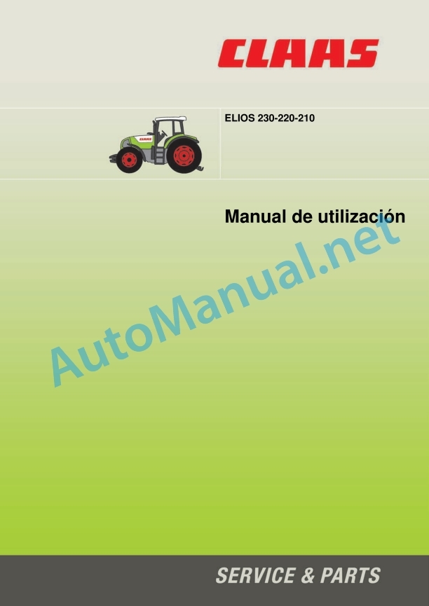
Claas Elios 200 (A28) Tractors Operator Manual ES
$50.00
- Model: Elios 200 (A28) Tractors
- Type Of Manual: Operator Manual
- Language: ES
- Format: PDF(s)
- Size: 18.3 MB
File List:
00 2151 804 3.pdf
00 2151 804 3.pdf:
. Information about this user manual
. Validity of the instructions for use
. Chapter symbols
A – Identification – Homologation – Safety
1. Tractor signal plate
2. Engine signal plate
3. Front axle signal plate
4. Cabin nameplate
5. European regulations
6. Security
6.1. Security instructions
6.1.1. Use according to assignment
6.1.2. Use not in accordance with assignment
6.1.3. Precautions to be taken before starting up
6.1.4. Tractor status
6.1.5. Adjustment or maintenance work – repairs
6.1.5.1. General rule
6.1.5.2. Placement on lifting arms
6.1.5.3. Electricity
6.1.5.4. Fuel
6.1.5.5. Coolant liquid
6.1.6. Circulation – Transport
6.1.7. Tractor use
6.1.7.1. General rule
6.1.7.2. Tractor wheelbase
6.1.7.3. Tool attachment
6.1.7.4. Driving
6.1.7.5. Permanent jobs
6.1.7.6. Work with tools powered by the power take-off
6.1.7.7. Severe applications
6.1.8. Toxic products
6.1.9. Air-conditioning
6.1.10. Cabin
6.1.11. Respect for the environment
6.1.12. Using a front loader
6.1.13. Forestry applications
6.2. Safety stickers with warning pictograms
6.2.1. recommendations
6.2.2. User manual
6.2.3. Coolant liquid
6.2.4. Engine
6.2.5. Transmission oil
6.2.6. External controls
6.2.7. rear hitch
6.2.8. seat belt
6.2.9. Fan
6.2.10. Engine belt
6.2.11. folding bow
6.2.12. Front tow hook
6.2.13. FOPS Roof
B – Driving position
1. Driving and working environment
1.1. Right side controls
1.2. Left side controls
1.3. Controls and instruments (dashboard)
1.4. Accommodations and accessories
2. Lighting, signage and security
2.1. Description
2.2. Low beam/high beam and klaxon
23. Low beam adjustment
2.4. Work lights and rotating headlight
2.5. Roof light
2.6. Mirrors
3. Start contactor
4. Driver’s seat
5. steering wheel
6. Dashboard
6.1. Description
6.2. Functioning
6.3. Utilization
6.4. Parameterization
6.4.1. Procedure
6.4.2. Speed parameter table
7. Openers and glass
8. Viewer
9. Heating – ventilation – manual air conditioning
9.1. Description
9.2. Utilization
Platform
1. Driving and working environment
1.1. Right side controls
1.2. Left side controls
1.3. Controls and instruments (dashboard)
2. Lighting, signage and security
2.1. Description
2.2. Low beam/high beam and klaxon
23. Low beam adjustment
2.4. Work lights and rotating headlight
2.5. Mirrors
3. Start contactor
4. Driver’s seat
5. steering wheel
6. Dashboard
7. Folding bow
C – ELECTRICITY
1. Features
2. Trailer/tool lighting socket
3. Power socket el. Battery
5. Fuses and relays
5.1. recommendations
5.2. Fuse box under the instrument panel
5.3. Engine compartment fuse box
5.3.1. Preheat fuse
5.3.2. Fuse and electronic lift relay
5.3.3. Main cabin fuse
5.4. Fuse box and main relay
5.5. Right pillar fuse box
5.6. Left pillar relay
5.7. Fuses and relays of the electrohydraulic distributors
D – Engine
1. Features
2. Visualizers
2.1. Dashboard
3. Security
3.1. Dashboard
3.2. recommendations
4. Engine hood
4.1. Monobloc hood
4.2. Side hoods
5. Engine control
5.1. Engine start
5.1.1. Preliminary operations
5.1.2. Start up
5.2. Using the accelerator pedal and lever
5.2.1. Functioning
5.2.2. Accelerator pedal
5.2.3. manual throttle
5.3. Engine stop
6.1. recommendations
6.2. Bleeding air from the injection circuit
E – Transmission
1. Features
2. Forward speeds
3. Indication
3.1. Dashboard
4. Security
4.1. Neutral inverter
4.1.1. UTILIZATION
4.1.2. Functioning
5. Setting in motion
5.1. Clutch
5.1.1. recommendations
5.1.2. Clutch pedal
5.1.3. contactor
5.2. Selection of feed direction
5.2.1. Mechanical gear reverser
5.2.2. Electrohydraulic reverse gear (reverser under load)
5.3. Speed selection
5.4. Bender
5.4.1. Mechanical range bender
5.4.2. Electrohydraulic range duplicator
5.5. Range selection
rear axle
1. Features
2. Protection of mechanical organs
3. Differential blocking
3.1. recommendations
3.2. Functioning
4. Brakes
4.1. Service brakes
4.2. Parking brake
4.2.1. Obligations
4.2.2. Parking brake (auxiliary and parking brake)
5. Trailer braking
5.1. Hydraulic brake
F – Front axle
1. Features
2. Synchronism relationship
3. Front axle gear
3.1. Generalities
3.2. Automatic mode
3.2.1. Utilion
.2. Functioning
3.3. Permanent mode
3.3.1. Utilization
3.3.2. Functioning
G – Rear equipment
Hydraulic
1. Features
2. Mechanical control auxiliary distributors
2.1. Association of rear controls/pressure taps
2.2. pressure taps
2.2.1. recommendations
2.2.2. Utilization
2.2.3. Free return to the warehouse
23. Double acting/single acting conversion
3. Electrohydraulic distributors
3.1. Association of rear controls/pressure taps
3.2. pressure taps
3.2.1. recommendations
3.2.2. Utilization
3.2.3. Free return to the warehouse
3.3. Controls
3.4. Start up
3.5. Online controls
3.6. Cross control
3.7. Adjustment of flow rates
3.8. Hydraulic timer
4. Permanent job
rear lift
1. Mechanical lifting
1.1. Characteristics
1.2. Controls
1.3. Position control
1.4. Effort control
1.5. Mixed control
1.6. Swing hitch
1.7. External controls
1.8. Sensitivity
2. TCE6 electro-hydraulic lifting
2.1. Characteristics
2.2. Controls
23. Security
2.3.1. safety pilot
2.3.2. Transportation security
2.4. Lift start-up
2.5. Mode selection
2.6. Position control
2.7. Effort control
2.8. High stop
2.8.1. Utilization
2.8.2. Functioning
2.9. Descent speed
2.10. Quick ground function
2.11. External controls
2.11.1. Utilization
2.11.2. Functioning
rear power take off
1. Features
2. Recommendations
3. Usage
4. Indication
5. PTO speed selection
6. Selection of the power take-off regime proportional to the advance
7. Attachment of tools to the power take-off
8. Permanent job
rear hitch
1. Features
2. Recommendations
3. Fixing mechanisms
4. Upper connecting rod
5. Automatic hooks
6. Mechanical stabilizers
7. Hitch Bolts
8. Swing bar
9. Pickup hitch
H – Front equipment
Front lift
1. Features
2. Distributor Controlled Front Lift 2
2.1. Controls
2.2. Preliminary operations
23. Utilization
2.3.1. Mechanical control distributor
2.3.2. Electrohydraulic distributor
3. 3-point hitch
3.1. lower cranks
3.2. Upper connecting rod
3.3. Hitching and unhitching the implement
front power take off
1. Features
2. Recommendations
3. Front PTO interlock
4. Front PTO stop
Front loader
1. Assembly of an adaptation structure for a front loader
J – Wheels and tires
1. Tires
1.1. recommendations
1.2. inflation pressure
1.2.1. Characteristics
1.2.2. recommendations
1.3. Load index
1.4. speed code
2. Paths
2.1. Commissioning
2.2. front tracks
2.2.1. Front bridge
2.2.2. Front Track Tables
2.2.3. Front axle swing stops
2.2.3.1. check
2.2.3.2. Adjustment
23. rear tracks
2.3.1. rear axle
2.3.2. Rear track boards
2.4. Tire combinations
K – Features
1. Dimensions
1.1. Cabin
1.2. Platform
2. Weight
2.1. Cabin
2.2. Platform
3. Loading capacities
4. Maximum permissible towable masses
5. Capacities
6. Weighted
6.1. Ballasts available
6.2. Tractor balancing
6.3. Compatibility of ballasts with tires
7. Cabin comfort
7.1. Sound level
7.2. vibration level
L – Maintenance
1. Recommendations
2. Trailer
3. Transportation
4. Using a jack
5. Changing a wheel
6. Tractor loading and stowage
7. Parking
8. Disablement and destruction
9. Periodicities
9.1. Summary table
9.2. Operations
9.2.1. Operation #1
9.2.2. Operation #2
9.2.3. Operation #3
9.2.4. Operation #4
9.2.5. Operation #5
9.2.6. Operation #6
9.2.7. Operation #7
9.2.8. Operation #8
9.2.9. Operation #9
9.2.10. Operation #10
9.2.11. Operation #11
9.2.12. Operation #12
9.2.13. Operation #13
9.2.14. Operation #14
9.2.15. Operation #15
9.2.16. Operation #16
9.2.17. Operation #17
9.2.18. Operation #18
9.2.19. Operation #19
9.2.20. Operation #20
9.2.21. Operation #21
9.2.22. Operation #22
9.2.23. Operation #23
9.2.24. Operation #24
9.2.25. Operation #25
9.2.26. Operation #26
9.2.27. Operation #27
9.2.28. Operation #28
9.2.29. Operation #29
9.2.30. Operation #30
9.2.31. Operation #31
9.2.32. Operation #32
9.2.33. Operation #33
9.2.34. Operation #34
9.2.35. Operation #35
9.2.36. Operation #36
9.2.37. Operation #37
9.2.38. Operation #38
9.2.39. Operation #39
9.2.40. Operation #40
9.2.41. Operation #41
9.2.42. Operation #42
9.2.43. Operation #43
9.2.44. Operation #44
9.2.45. Operation #45
9.2.46. Operation #46
9.2.47. Operation #47
9.2.48. Operation #48
9.2.49. Operation #49
9.2.50. Operation #50
9.2.51. Operation #51
9.2.52. Operation #52
9.2.53. Operation #53
9.2.54. Operation #54
9.2.55. Operation #55
9.2.56. Operation #56
9.2.57. Operation #57
10. Bleeding the air from the injection circuit
11. Maintenance operations logbook
M – Mandatory warranty operations
1. MANDATORY OPERATIONS CARRIED OUT WITHIN THE FRAMEWORK OF THE CONTRACTUAL WARRANTY
1.1. Inspection before delivery
1.2. Customer delivery
1.3. MAINTENANCE OPERATIONS TO BE CARRIED OUT
1.4. Mandatory visits
1.4.1. Mandatory inspection after the first 100 hours
1.4.2. Mandatory visit within the first 500 hours or between the 8th and 10th month
Alphabetical index
John Deere Repair Technical Manual PDF
John Deere Repair Technical Manual PDF
John Deere Repair Technical Manual PDF
John Deere DF Series 150 and 250 Transmissions (ANALOG) Component Technical Manual CTM147 05JUN98
John Deere Repair Technical Manual PDF
John Deere Parts Catalog PDF
John Deere Tractors 7500 Parts Catalog CPCQ26568 30 Jan 02 Portuguese
John Deere Repair Technical Manual PDF
John Deere Repair Technical Manual PDF
John Deere Parts Catalog PDF
John Deere Tractors 6300, 6500, and 6600 Parts Catalog CQ26564 (29SET05) Portuguese
John Deere Repair Technical Manual PDF
John Deere Repair Technical Manual PDF
John Deere Diesel Engines PowerTech 4.5L and 6.8L – Motor Base Technical Manual 07MAY08 Portuguese


