Claas Elios 240-210 Stage V (A68) Tractors Technical System EN
$300.00
- Model: Elios 240-210 Stage V (A68) Tractors
- Type Of Manual: Technical System
- Language: EN
- Format: PDF(s)
- Size: 195 MB
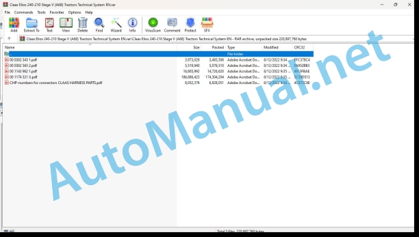
File List:
00 0302 343 1.pdf
00 0302 565 2.pdf
00 1143 962 1.pdf
00 1174 321 X.pdf
CHP-numbers for connectors CLAAS HARNESS PARTS.pdf
00 0302 343 1.pdf:
PROFI CAM 3
Table of contents
General information
Marking of warnings and hazard prevention notes
First-aid measures
CCN explanation
CCN (CLAAS Component Number)
Electric system standard
Overview
Hydraulic system standard
Overview
CCN (CLAAS Component Number)
10 Electrical / Electronic equipment
1030 Board computer / Indicators
Camera system
Description of function
1097 Testing / Measuring / Adjusting
Testing / measuring / adjusting the PROFI CAM
Checking the fuse in the video channel select box (C102)
Testing the video camera connector (C055)
1098 Fault / remedy
Fault / remedy PROFI CAM
The video monitor (C101) shows no image or cannot be switched on (indicator light fails to light up)
Video monitor (C102) displays a blue image either permanently or temporarily
The video monitor image is blurred
Replacing the fuse in the video channel select box (C102)
Connection and connecting cable with video camera (C055)
00 0302 565 2.pdf:
Sensor system
Table of contents
CCN explanation
CCN (CLAAS Component Number)
Electric system standard
Overview
Hydraulic system standard
Overview
CCN (CLAAS Component Number)
Introduction
Safety rules
Safety and hazard information
10 Electrical / Electronic equipment
1097 Testing / Measuring / Adjusting
Test report of the angle sensor (0011780.x)
Application of test report
Required tools
Test report of the angle sensor (0011780.x)
Testing / Measuring / Adjusting of angle sensor (0011780.x)
1. Reason for test
2. Mechanical test of angle sensor
3. Electric test with CDS
4. Electric test with multimeter
5. Mechanical test of connecting cable
Completing the machine
Test report of position and speed sensors
Application of test report
Required tools
Sensor variants
Part numbers of speed sensors
Part number of position sensor
Test report of position and speed sensors
Testing / measuring / adjusting of position and speed sensors
1. Reason for test
2. Mechanical test
3. Electric test with CDS
4a. Installation dimensions
Check of installation dimension
Installation dimensions of gearbox speed sensor (0011 799.x) and cam speed sensor (0011 810.x)
Installation dimension of position sensor (0011 815.x)
4b. Installation position
Centring of sensor
Metal-free zone
5. Electric test with multimeter
Voltage measurement
Direction of rotation and speed sensor (0011 605.x)
Measured values table
6. Mechanical test of connecting cable
Completing the machine
Test report of the urea sensor (00 0773 207 x)
Application of test report
Required tools
Parts number of the urea sensor
Test report of the urea sensor
Testing / measuring / adjusting urea sensor
1. Reason for test
2. Mechanical test
3. Mechanical test of connecting cable
4. Electric test with multimeter
5. Component test with the CDS
00 1143 962 1.pdf:
FL – FLC – FLE loaders
Table of contents
CCN explanation
CCN (CLAAS Component Number)
Electric system standard
Overview
Hydraulic system standard
Overview
CCN (CLAAS Component Number)
Introduction
General information
Using this diagnostic manual
Safety rules
Safety instructions and risk information
Validity of manual
Validity of this diagnostic manual
06 Lift device
0615 Front loader
Reminder
Control valve slide valves
Lifting circuit
“Shock Eliminator System” (Option)
Loading circuit
Loading circuit of FL loaders
Loading circuit of – FLE loaders
Parallelogram hydraulic circuit
Hydraulic parallelogram – “PCH System”
3rd function circuit
Loading retarder
4th function circuit
Safety system circuit
“ACS” circuit
“SCS” circuit
“Fast-Lock System” circuit
“Speed-Link System” circuit
Mechanical part
0698 Problems / remedy
Faults on the Mach System
Appearance of oil leaks
Faults on Flexpilot System
Open centre: Hydraulic malfunction noted on the tractor
Open centre: Loader does not lift the load stated
Load sensing signal (LS): Hydraulic malfunction noted on the tractor
Load sensing signal: Loader does not lift the load stated
Faults on Flexpilot System
Appearance of jerking relating to the hydraulic system
Abnormally hard to move the control lever
Control valve body rupturing underure as soon as the vehicle is first switched on
Response time too long
Appearance of oil leaks outside the control valve
Loader lowering by itself
Faults on loading circuit
Loader dumping by itself
Lack of power when digging or unloading
Checking the loader solenoid valves
Characteristics of the solenoid valves
Solenoid valve not working
Dismantling the solenoid valve
Dismantling the solenoid valve of the 3rd function on the FL loader
User advice in order to avoid clogging the solenoid valves
10 Electrical / Electronic equipment
1015 Wiring harnesses
Overview of the FL loader wiring harnesses
Wiring harness for loader equipped with 3rd function
Wiring harness for loader equipped with 3rd function and 4th function
Wiring harness for loader equipped with 3rd function, 4th function, ACS and “Fast-Lock” or “Speed-Link”
Wiring harness for loader equipped with 3rd function, 4th functioACS and “Fast-Lock” or “Speed-Link”
Wiring harness for safety loader on the lifting and loading circuit
Overview of the FLC loader wiring Wiring harness for loader equipped with 3rd function
Wiring harness for loader equipped with 3rd function and 4th function
Wiring harness for loader equipped with 3rd function, 4th function, and “Fast-Lock”
Wiring harness for loader equipped with safety function on lifting and loading
Overview of FLE loader wiring harnesses
Wiring harness for loader equipped with 3rd function
Wiring harness for loader equipped with safety function on lifting and loading
Position of components
Hydraulic system
3000 Hydraulic cylinders
5000 Accumulators
8000 Couplings – Connections
Electric system
V Electronic components
X Connections
Y Electromagnetic coil
00 1174 321 X.pdf:
ELIOSble of contents
CCN (CLAAS Component Number)
CCN explanation
CCN (CLAAS Component Number)
Electric system standard
Overview
Hydraulic system standard
Overview
CCN Index
Introduction
Validity of manual
Validof this diagnostic manual
01 Engine
0125 Injection / Fuel system
Fuel supply circuit
Table of measurement values
Description of the function
Fuel supply circuit hydraulic diagram
Checking the fuel supply pressure
Fuel injection circuit
Table of measurement values
Description of the function
Calibrating the accelerator pedal sensor (B153) and the engine speed adjustment sensor (B154)
CLAAS POWER MANAGEMENT sensor calibration
Fuel injection circuit hydraulic diagram
Fuel return circuit
Engine wiring harness
Power recording sheets
Preparation for work
Unit conversions
Calculation formula
0130 Lubricating oil system
Engine lubrication circuit
Table of measurement values
Description of the function
Hydraulic diagram of the engine lubrication circuit
Checking the engine lubrication pressure
0135 Cooling system
Engine cooling circuit
Table of measurement values
Description of the function
Checking the engine thermostat
0140 Exhaust system
Engine exhaust circuit
Table of measurement values
Description of the function
Diagram of the exhaust gases and recycled exhaust gases circuit
Checking the “EGR” cooler
0145 Air intake
Engine air intake circuit
Table of measurement values
Description of the function
0150 Engine attachment parts
Starting the engine
Table of measurement values
Description of the function
0155 Engine control
Engine speed setpoint
Table of measurement values
Description of the function
0165 Exhaust gas aftertreatment
ne post-treatment system
Table of measurement values
Description of the function
Automatic regeneration
Stationary or service regeneration
0198 Problem / Remedy
18F-2 — Oxygen sensor fault
18F-3 — Oxygen sensor circuit (B539) short-circuited
18F-4 — Oxygen sensor circuit (B539) short-circuited
601n sensor (B539) circuit open
602-2 — Oxygen sensor (B539) circuit open
605-3 — Oxygen sensor fault
606-2 — Oxygen sensor (B539) circuit open
607-3 — Oxygen sensor fault
607-4 — Oxygen sensor fault
609-2 — ECU: internal error
60A-4 — Oxygen sensor fault
60B-3 — Oxygen sensor (B539) circuit short-circuited
60B-4 — Oxygen sensor (B539) circuit short-circuited
60C-3 — Oxygen sensor fault
60C-4 — Oxygen sensor fault
02 Gearbox / Clutch / Universal drive shaft
0202 Complete component
Transmission kinematics
12 + 12 transmission
24 + 24 transmission with mechanical doubler
raulic doubler
24 + 12 transmission with hydraulic reverser and mechanical rear power take-off clutch
24 + 12 transmission with hydraulic reverser and hydraulic rear power take-off clutch
Load distribution
0220 Mechanical reverser
Mechanical reverser
0222 Hydraulical reverser
Revershift hydraulic reverser
Table of measuremention of the function
Operation and adjustment of the clutch pedal
Interface menu for the transmission control module TCU A057
Configuring the tractor model
Clutch pedal calibration menu
Error messages which may be displayed during the calibration procedure
Clutch pressure sensors calibration menu
Error messages which may be displayed during the calibration procedure
Lever progressivity adjustment menu
Pedal progressivity adjustment menu
Hydraulic doubler progressivity adjustment menu
Limp Home function activation menu
Diagnostic help menu for the Revershift, doubler control and clutch pedal
Checking the supply pressure of the hydraulic reverser clutches
0230 Mechanical gearbox
Mechanical doubler, mechanical ranges and gears
0234 Powershift gearbox
Twinshift hydraulic doubler
0242 Differential
Rear differential lock
Table of measurement values
Functional logic
Checking the differential supply pressure
0252 Electro-hydraulical front axle drive
Four-wheel drive
Table of measurement values
Functional logic
Checking the four-wheel drive power take-off supply pressure
03 Chassis
Steering axle
Four-wheel drive
04 Brake
0405 Service brake
Service brake
0425 Trailer hydraulic brake
Trailer hydraulic brake
Table of measurement values
05 Steering
0505 Steering
Main steering
Checking the steering pressure relief valve 7026
Checking the opening pressure of the shockproof valves 7153
06 Lift device
0605 Rear power lift
Mechanical rear linkage
Neutral position
Lowering position
Raising position
Checking the rear linkage shock valve
Electronic rear linkage
Linkage control valve
Rear linkage calibration procedure
Setting the shock valve pressure
Preliminary operations
Special tool
Adjustment
08 Drives
0802 Rear PTO
Rear power take-off with electrohydraulic control
Functional logic
Checking the power take-off brake supply pressure
Checking the power take-off clutch pressure
Mechanically controlled rear power take-off
Functional logic
09 Hydraulic system
0910 Pumps
2-pump hydraulic circuit
3-pump hydraulic circuit
Checking the flow rate of the hydraulic steering pump 2018
Checking the flow rate of the auxiliary hydraulic pump (2027)
Checking the flow rate of the hydraulic pump (2015) (Linkage)
0915 Hydraulic lines
12-12 transmission hydraulic circuit
Hydraulic circuit for 24-24 transmission with mechanical doubler
Hydraulic circuit for 24-24 transmission with TWINSHIFT hydraulic doubler
REVERSHIFT 24-12 transmission hydraulic circuit
0920 Valves
Hydraulic circuit with 2 pumps and 2 control valves
Hydraulic circuit with 2 pumps and 3 control valves
Hydraulic circuit with 2 pumps and 3 control valves with centre flow controller
Hydraulic circuit with 3 pumps and 3 control valves with centre flow controller
Hydraulic circuit with 3 pumps and electrohydraulic control valves
0935 Hydraulic system control / monitoring
Monitoring the hydraulic system
Table of measurement values
0980 Hydraulic circuit diagrams
12-12 transmission hydraulic circuit plan
Plan of hydraulic circuit for 24-24 transmission with mechanical doubler
24-24 transmission with TWINSHIFT hydraulic doubler hydraulic circuit plan
REVERSHIFT 24-12 transmission hydraulic circuit plan
10 Electrical / Electronic equipment
1010 Central electrics
Engine front section fuse box
Allocation of fuses
Allocation of relays
Main fuse box
Dashboard fuses
Right-hand post fuse box
Allocation of fuses
Left-hand post relay
Allocation of relays
Right-hand console fuse box (rear linkage and electrohydraulic control valves)
Allocation of fuses
Allocation of relays
Allocation of relays
Earth points
1012 Modules / sensors
Overview of modules
A015 Engine control module
A057 Transmission control module
A058 Linkage module
A060 Hydraulic control module
A101 Dashboard module
A101 Dashboard module (tractor with mechanical rear power take-off)
A101 Dashboard module (tractor with hydraulic rear power take-off)
A117, A118, A119, A120 Control valves 1, 2, 3, 4
A147 Rear linkage control panel
A174 Multifunction control module
1015 Wiring harnesses
Set of cables
W22 – Earth cable
List of connectors
W45-1 – Positive starter cable
List of connectors
Engine wiring harness
W02 – Engine wiring harness
List of connectors
Cab and platform wiring harness
W04 – Cab roof wiring harness
List of connectors
W04-3 – Windscreen washer motor wiring harness
List of connectors
W04-4 – Cab roof supply wiring harness
List of connectors
W16 – Lighting wiring harness H4
List of connectors
W17 – Warning beacon wiring harness (platform)
List of connectors
W19 – Windscreen wiper wiring harness
List of connectors
W25 – Gearbox +/- control wiring harness
List of connectors
W29 – Dashboard wiring harness (tractor with mechanical reverser)
List of connectors
W29 – Dashboard wiring harness (tractor with REVERSHIFT)
List of connectors
W31 – Right-hand console wiring harness (tractor with mechanical reverser)
List of connectors
W31 – Right-hand console wiring harness (tractor with REVERSHIFT)
List of connectors
W35 – Warning beacon adaptation wiring harness
List of connectors
W36 – Wiring harness for cab roof, heating and air conditioning
List of connectors
Front section wiring harness
W05 – Bonnet wiring harness
List of connectors
W05-1 – Dashboard-bonnet connection wiring harness
List of connectors
W33 – Front power take-off wiring harness
List of connectors
W33-1 – Front power take-off connection to the solenoid valve wiring harness
List of connectors
Control valves and rear linkage wiring harness
W10 – Rear linkage control wiring harness (with electrohydraulic control valves)
List of connectors
W10-1 – Electrohydraulic control valve wiring harness
List of connectors
W10-2 – Control valve control power supply wiring harness
List of connectors
W10-3 – Rear linkage raising/lowering switch wiring harness
List of connectors
W11 – Rear linkage control wiring harness (without electrohydraulic control valves)
List of connectors
W11-1 – Rear linkage control wiring harness (without electrohydraulic control valves)
List of connectors
W11-3 – Rear linkage external control wiring harness
List of connectors
Transmission wiring harness
W06 – Trailer brake wiring harness
List of connectors
W30 – Main wiring harness (tractor with mechanical reverser)
List of connectors
Main wiring harness (tractor with REVERSHIFT)
List of connectors
1080 Electrical circuit diagram
SCM02 Road indicators
SCM02-01 Warning beacon (platform version)
List of components
List of wiring harnesses
SCM02-01 Warning beacon (cab version)
List of components
List of wiring harnesses
SCM02-02 Running lights and horn
List of components
List of wiring harnesses
SCM02-03 Side lights, indicators and brake lights (platform version)
List of components
List of wiring harnesses
SCM02-03 Side lights, indicators and brake lights (cab version)
List of components
List of wiring harnesses
SCM04 Linkage, electrohydraulic control valves and power take-off
SCM04-01 Rear linkage (with electrohydraulic control valves)
List of components
List of wiring harnesses
SCM04-01 Rear linkage (without electrohydraulic control valves)
List of components
List of wiring harnesses
SCM04-02 Front and rear power take-off (mechanical rear power take-off)
List of components
List of wiring harnesses
SCM04-02 Front and rear power take-off (hydraulic rear power take-off)
List of components
List of wiring harnesses
SCM06 Transmission
SCM06-01 Four-wheel drive and differential
List of components
List of wiring harnesses
SCM06-02 REVERSHIFT and TWINSHIFT
List of components
List of wiring harnesses
SCM06-03 Mechanical doubler
List of components
List of wiring harnesses
SCM07 Accessories
SCM07-01 Cab roof
List of components
List of wiring harnesses
SCM10 CAN network
SCM10-01 CAN network (tractor with mechanical reverser)
List of components
List of wiring harnesses
SCM10-01 CAN network (tractor with REVERSHIFT)
List of components
List of wiring harnesses
SCM11 Supply
SCM11-01 Supply (tractor with mechanical reverser)
List of components
List of wiring harnesses
SCM11-01 Supply (tractor with REVERSHIFT)
List of components
List of wiring harnesses
SCM12 Tractor – implement connections
SCM12-01 Power supply socket (tractor with mechanical reverser)
List of components
List of wiring harnesses
SCM12-01 Power supply socket (tractor with REVERSHIFT)
List of components
List of wiring harnesses
SCM13 Braking
SCM13-01 Pneumatic braking
List of components
List of wiring harnesses
SCM18 Engine
SCM18-01 Engine
List of components
List of wiring harnesses
SCM18-02 Engine controls (tractor with mechanical reverser)
List of components
List of wiring harnesses
SCM18-02 Engine controls (tractor with REVERSHIFT)
List of components
List of wiring harnesses
SCM19 Instrument panel
SCM19-01 Instrument panel
List of components
List of wiring harnesses
1085 Networks
CAN bus network architecture
CAN bus network
Location of CAN bus resistors
92 Diagnosis
Presentation of error codes
Introduction
Display of error codes
Description
CCN, SPN and the FMI standard
FMI 00 (signal too high)
FMI 01 (signal too low)
FMI 02 (signal not plausible)
FMI 03 (voltage too high)
FMI 04 (voltage too low)
FMI 05 (current too low)
FMI 06 (current too high)
FMI 07 (mechanical error)
FMI 08 (incorrect frequency signal)
FMI 09 (communication error)
FMI 10 (signal modification too quick)
FMI 11 (multiple errors)
FMI 12 (ECU faulty)
FMI 13 (signal outside calibration range)
FMI 16 (non-existent parameter)
FMI 17 (ECU not responding)
FMI 18 (voltage supply error)
FMI 19 (software conditions not satisfied)
FMI 95 (no signal modification)
FMI 96 (faulty CAN Bus system)
FMI 97 (status not plausible)
FMI 98 (warning)
FMI 99 (Info)
9210 Error codes machine
Conversion table for codes shown on the instrument panel display
List of error codes
Diagnostic logs
Checking the circuits – Recommendations
0x30c – Error on accelerator pedal sensor (B153)
0x30d – Error on the accelerator pedal sensor (B153)
0x30e – Error on the accelerator pedal sensor (B153)
0x30f – Error on the engine speed adjustment sensor (B154)
0x310 – Error on the engine speed adjustment sensor (B154)
0x313 – Error on the engine speed adjustment sensor (B154)
0x314 – Error on the right-hand brake pedal switch (Z127)
0x315 – Error on the 4-wheel drive switch (S001)
0x316 – Error on the 4-wheel drive oil pressure switch (Z234)
0x317 – Error on the 4-wheel drive oil pressure switch (Z234)
0x318 – Error on the differential lock switch (S094)
0x319 – Error on the differential oil pressure switch (Z235)
0x31a – Error on the differential oil pressure switch (Z235)
0x31b – Error on the engine speed 1 storage button (S178)
0x31c – Error on the engine speed + switch (S188)
0x31d – Error on the engine speed – switch (S189)
0x31e – Error on the engine speed 2 storage button (S179)
0x31f – Hydraulic doubler error
0x320 – Error on the gearbox +/- control (C089)
0x321 – Error on the gearbox +/- control (C089)
0x322 – Error on the power take-off brake solenoid valve (Y338)
0x323 – Error on the rear power take-off clutch solenoid valve (Y325)
0x324 – Computer: internal error
0x325 – Error on the rear power take-off on/off switch (S114)
0x326 – Error on the 540 rpm power take-off engaged switch (Z161)
0x327 – Error on the 540 rpm power take-off engaged switch (Z161)
0x328 – Error on the 540 rpm power take-off engaged switch (Z161)
0x329 – Error on the 540-1000 rpm power take-off switch (Z208)
0x32a – Error on the 540-1000 rpm power take-off switch (Z208)
0x32b – Error on the 540-1000 rpm power take-off switch (Z208)
0x32c – Power take-off speed selection error
0x32d – Error on the proportional power take-off disengaged switch (Z210)
0x32e – Error on the proportional power take-off disengaged switch (Z210)
0x32f – Error on the proportional power take-off disengaged switch (Z210)
0x330 – Error on the proportional power take-off switch (Z162)
0x331 – Error on the proportional power take-off switch (Z162)
0x332 – Error on the proportional power take-off switch (Z162)
0x333 – Power take-off speed selection error
0x334 – Error on the CLAAS Power Management sensors (B047 and B228)
0x335 – Error on the CLAAS Power Management sensor (B047)
0x336 – Error on the CLAAS Power Management sensor (B228)
0x337 – Error on the power take-off oil pressure switch (Z175)
0x338 – Error on the power take-off oil pressure switch (Z175)
0x339 – Error on the power take-off brake solenoid valve (Y338)
0x33a – Error on the rear power take-off clutch solenoid valve (Y325)
0x33b – Power take-off clutch actuation pressure error
0x33c – Error on the rear power take-off rotation speed sensor (B142)
0x350 – Error on the left-hand brake pedal switch (Z126)
0x352 – Write error in the internal memory of the dashboard module (A101)
0x593 – Internal failure in the dashboard module (A101)
0x594 – Fault in the DBD dashboard module (A101)
0x596 – Internal failure in the dashboard module (A101)
0x597 – CAN bus error
0x598 – Fault in the DBD dashboard module (A101)
0x599 – Error on four-wheel drive automatic control switch (S335)
0x59a – Error on the steering angle sensor (B117)
0x59b – Error on the theoretical ground speed sensor (B227)
0x59c – Error on the front power take-off relay
0x59d – Error on the power take-off safety deactivation switch (S334)
0x626a – Hydraulic oil temperature too high
0x7100 – Output voltage for the clutch pedal sensor (B361) too high
0x7101 – Output voltage for the clutch pedal sensor (B361) too low
0x7102 – Output signal for the clutch pedal sensor (B361) too low
0x7103 – Output signal for the clutch pedal sensor (B361) too high
0x7104 – Signals for the clutch pedal sensor (B361) and triggering of the inching contact not synchronised
0x7105 – Output signal for the reverse gear clutch pressure sensor (B383) greater than 5 V
0x7106 – Output signal for the reverse gear clutch pressure sensor (B383) less than 0.2 V
0x7107 – Supply voltage for the pressure sensors (B383, B384 and B385) above 5.5 V
0x7108 – Supply voltage for the pressure sensors (B383, B384 and B385) below 4.5 V
0x7109 – Output signal for the slow forward gear clutch pressure sensor (B384) greater than 5 V
0x710a – No electrical signal coming from the clutchless reverser lever (C073) or no driver in the seat (depending on the equipment)
0x710b – Forward and reverse gear signals sent simultaneously by the clutchless reverse lever (C073)
0x710c – Forward gear and neutral signals sent simultaneously by the clutchless reverse lever (C073)
0x710d – Reverse gear and neutral signals sent simultaneously by the clutchless reverse lever (C073)
0x710e – Forward gear, reverse gear and neutral signals sent simultaneously by the clutchless reverser lever (C073)
0x7110 – Output signal for the slow forward gear clutch pressure sensor (B384) less than 0.2 V
0x7111 – Output signal for the fast forward gear clutch pressure sensor (B385) greater than 5 V
0x7112 – Output signal for the fast forward gear clutch pressure sensor (B385) less than 0.2 V
0x7114 – Pressure in the reverse gear clutch is less than 0.250 bar when pressurised
0x7115 – Pressure in the reverse gear clutch is greater than 0.9 bar when the reverse gear clutch is not supplied
0x7116 – Reference values for the reverse gear clutch solenoid valve (Y233) outside of usage ranges
0x7119 – No current feedback for the reverse gear solenoid valve (Y233) detected when it is supplied
0x711a – Current feedback for the reverse gear solenoid valve (Y233) detected when it is not supplied
0x711b – Reverse gear clutch solenoid valve (Y233): difference between the measured current and the reference current
0x711d – Abnormal slipping of the reverse gear clutch
0x711e – Reverse gear clutch: difference of 0.5 bar between the measured pressure and the reference pressure
0x7120 – Fault in the TCU transmission control module (A057)
0x7120 – Fault in the TCU transmission control module (A057)
0x7120 – Fault in the TCU transmission control module (A057)
0x7120 – Fault in the TCU transmission control module (A057)
0x7120 – Fault in the DBD dashboard module (A101)
0x7122 – Supply voltage for the TCU transmission control module (A057) less than 9 V
0x7123 – Supply voltage for the TCU transmission control module (A057) greater than 16 V
0x7124 Corruption of the flash memory calibration parameters
0x7125 – CAN bus error
0x7127 – Oil temperature less than – 20°C
0x7129 – Signal from the hydraulic oil temperature sensor (B123) too high
0x712a – Signal for the hydraulic oil temperature sensor (B123) too low
0x712b – Fault on the gearbox speed intermediate sensor (B229)
0x712d – Fault on the signal of the gearbox speed intermediate sensor (B229)
0x712e – Fast forward gear clutch slipping too great
0x712f – Slow forward gear clutch slipping too great
0x713e – Overcurrent at all the outputs on the TCU transmission control module (A057)
0x714 – Supply error on the TCU transmission control module (A057)
0x7146 – CAN bus communication error
0x7147 – CAN bus communication error
0x7212 – Overcurrent detected on the supply of the transmission safety solenoid valve (Y506)
0x7214 – Overcurrent detected on the feedback of the transmission safety solenoid valve (Y506) or on the feedback of the rear power take-of clutch solenoid valve (Y325)
0x7215 – Pressure in the fast forward gear clutch is less than 0.250 bar when pressurised
0x7216 – Pressure in the fast forward gear clutch is greater than 0.9 bar when the fast forward gear clutch is not supplied
0x7217 – Reference values for the fast forward gear clutch solenoid valve (Y507) outside of usage ranges
0x7218 – No current feedback for the fast forward gear clutch solenoid valve (Y507) detected when it is supplied
0x7219 – Current feedback for the fast forward gear clutch solenoid valve (Y507) detected when it is not supplied
0x721a – Fast forward gear clutch solenoid valve (Y507): difference between the measured current and the reference current
0x721b – Fast forward gear clutch: difference of 0.5 bar between the measured pressure and the reference pressure
0x721c – Overcurrent is detected on the fast forward gear clutch solenoid valve (Y507) or on the reverse gear clutch solenoid valve (Y233)
0x721d – Pressure in the slow forward gear clutch is less than 0.250 bar when pressurised
0x721e – Pressure in the slow forward gear clutch is greater than 0.9 bar when the slow forward gear clutch is not supplied
0x721f – Reference values for the slow forward gear clutch solenoid valve (Y508) outside of usage ranges
0x7225 – Overcurrent detected on the slow forward gear clutch solenoid valve (Y508)
0x7226 – No current feedback for the slow forward gear clutch solenoid valve (Y508) detected when it is supplied
0x7227 – Current feedback for the slow forward gear clutch solenoid valve (Y508) detected when it is not supplied
0x722a – Slow forward gear clutch solenoid valve (Y508): difference between the measured current and the reference current
0x722b – Slow forward gear clutch: difference of 0.5 bar between the measured pressure and the reference pressure
0x722e – Differential pressure detected on the filter when the engine is running and the transmission oil temperature is greater than 20°C
0x722f – Fault onthe filter bypass pressure switch (Z102)
0x7233 – The low pressure circuit switch (Z184) detects a pressure below 7 bar
0x7236 – The low pressure circuit switch (Z184) detects pressure when the engine is stopped
0x7237 – The low pressure circuit switch (Z184) detects pressure when the engine is started and the transmission safety solenoid valve (Y506) is not supplied
0x7239 – Fault in the TCU transmission control module (A057)
0x723b – Write error in the internal memory of the transmission control module
9220 Error cod
John Deere Parts Catalog PDF
John Deere Tractors 6300, 6500, and 6600 Parts Catalog CQ26564 (29SET05) Portuguese
John Deere Repair Technical Manual PDF
John Deere Diesel Engines POWERTECH 2.9 L Component Technical Manual CTM126 Spanish
John Deere Repair Technical Manual PDF
John Deere 16, 18, 20 and 24HP Onan Engines Component Technical Manual CTM2 (19APR90)
John Deere Repair Technical Manual PDF
John Deere Repair Technical Manual PDF
John Deere Diesel Engines PowerTech 4.5L and 6.8L – Motor Base Technical Manual 07MAY08 Portuguese
John Deere Repair Technical Manual PDF
John Deere Repair Technical Manual PDF
John Deere Parts Catalog PDF
John Deere Harvesters 8500 and 8700 Parts Catalog CPCQ24910 Spanish
John Deere Repair Technical Manual PDF

