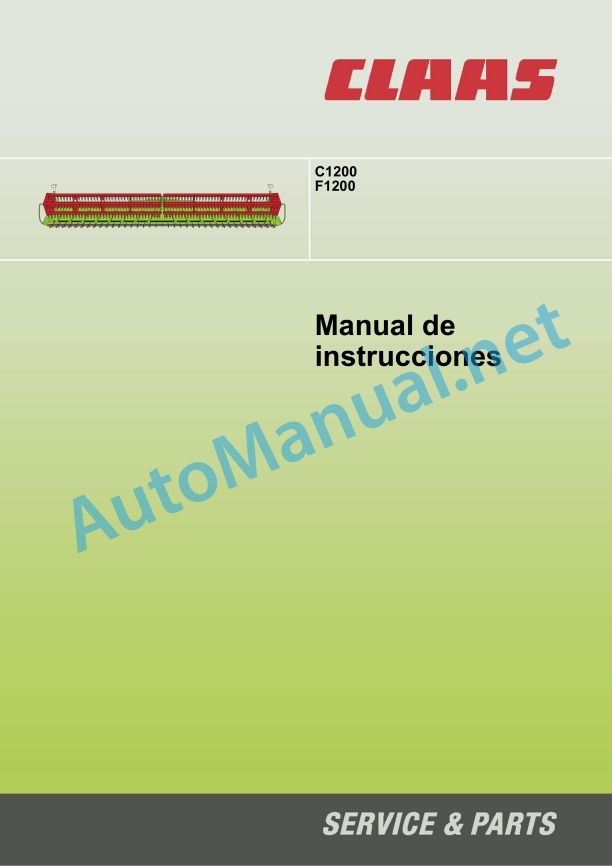
Claas F1200 C1200 Soja Getreide Lexion (442) Combines Operator Manual ES
$50.00
- Model: F1200 C1200 Soja Getreide Lexion (442) Combines
- Type Of Manual: Operator Manual
- Language: ES
- Format: PDF(s)
- Size: 6.7 MB
File List:
00 0293 969 2.pdf
00 0293 969 2.pdf:
1. Introduction
1.1 General instructions
1.1.1 Using the instructions
1.1.2 Validity of instructions
1.1.3 Technical data
1.2 Identification plates and identification numbers
1.2.1 Spare parts and technical issues
1.2.2 Identification plate
2 Overview
2.1 General view of front implement
2.1.1 F1200 overview
2.1.2 Overview C1200
3 Security measures
3.1 General instructions
3.1.1 Especially important
3.1.2 General prescriptions for safety and accident prevention
3.1.3 Proper use of the machine
3.1.4 Predictably foolish misuse
3.1.5 Precautionary measures
3.2 General safety warnings
3.2.1 Insert feed channel safety support
3.2.2 Remove the safety support from the feed channel
3.2.3 Insert the reel safety support
3.2.4 Remove the safety supports from the windlass
3.2.5 Install the cutter bar protection bar
3.2.6 Pressurized air and water
3.2.7 Risk of accident due to hydraulic fluid
3.2.8 Prevention against burns
3.2.9 Oil
3.2.10 Prevention against fires and explosions
3.2.11 Pipes, tubes and hoses
3.2.12 Before each start-up
3.2.13 Commissioning of the machine
3.2.14 Road traffic
3.2.15 Park
3.2.16 First aid measures
3.2.17 Decommissioning and waste disposal
3.3 Safety instructions
3.3.1 Warning and danger signs
3.4 Warning symbols
3.4.1 General instructions regarding warning symbols
3.4.2 Machine body
3.4.3 Windlass
3.4.4 Drives
4 Technical data
4.1 F1200 – TYPE 442
4.1.1 Measurements
4.1.2 Weights
4.1.3 Cutter bar
4.1.4 Power supply unit
4.1.5 Windlass
4.1.6 Safety devices
4.2 C1200 – TYPE 442
4.2.1 Measurements
4.2.2 Weights
4.2.3 Cutter bar
4.2.4 Power supply unit
4.2.5 Windlass
4.2.6 Safety devices
5 Before first start-up
5.1 General warnings
5.2 General instructions
5.2.1 Checklist for first start-up
5.3 Windlass
5.3.1 Remove the safety equipment for transporting the reel
6 Before each start-up
6.1 General warnings
6.2 General instructions
6.2.1 Commissioning checklist
7 Assembling/disassembling the front implement
7.1 General warnings
7.2 Assembly and general adjustments
7.2.1 Mount front implement
7.2.2 Remove front implement
7.2.3 Setting the cutting angle of the HP feed channel (optional equipment) to the basic setting
7.3 Drives
7.3.1 Assemble cardan shaft
7.3.2 Remove cardan shaft
7.4 Hydraulic system
7.4.1 Assemble multicoupling
7.4.2 Dismantle multicoupling
7.5 Machine body
7.5.1 Hang front implement
7.5.2 Lock front implement
7.5.3 Unlock front implement
7.5.4 Unhook front implement
8 Setting in operational mode
8.1 General warnings
8.2 General adjustment operational service
8.2.1 Adjust front implement for soybean harvest (optional equipment)
8.2.2 Adjust front implement for cereal harvesting (optional equipment)
8.3 Electrical installation
8.3.1 Modify cutting height sensor for cereal harvest (optional equipment)
8.3.2 Modify cutting height sensor for soybean harvest (optional equipment)
8.4 Cutter bar
8.4.1 Modify cutter bar for cereal harvesting (optional equipment)
8.4.2 Modify cutter bar for soybean harvesting (optional equipment)
8.4.3 Modify soybean harvesting blades (optional equipment)
8.4.4 Modify grain harvesting knives (optional equipment)
8.4.5 Mount crop lifter (optional equipment)
8.4.6 Remove crop lifters (optional equipment)
8.4.7 Adjust skids (optional equipment)
9 Operational service
9.1 General warnings
9.2 General handling
9.2.1 Before operational service in the field
9.2.2 Check harvest collection
9.2.3 Basic soybean harvest regulation (optional equipment)
9.2.4 Basic regulation for cereal harvesting (optional equipment)
9.2.5 Adjust cutting height for soybean harvest (optional equipment)
9.2.6 Adjust HP carry cutting angle (optional equipment)
9.3 Power supply unit
9.3.1 Adjust scraper strip
9.3.2 Adjust feed auger position
9.3.3 Adjust feed auger fingers
9.3.4 Extension auger plate
9.3.5 Remove extension of the auger plate
9.3.6 Mount extension of the auger plate
9.3.7 Adjust feed auger speed
9.4 Cutter bar
9.4.1 Move the table height from the machine (optional equipment)
9.4.2 Move the table height from the front implement (optional equipment)
9.4.3 Adjusting the speed of the blade drive (additional equipment)
9.5 Additional equipment
9.5.1 Mounting scraper strips (additional equipment)
9.6 Windlass
9.6.1 Adjust reel tines
9.7 Harvest dividers
9.7.1 Adjust soybean crop divider (optional equipment)
10 Failures and solutions
10.1 General warnings
10.2 General faults and solutions
10.2.1 Harvest material is not collected
10.2.2 The cutting mechanism is not straight
10.2.3 The material flow of the cutting mechanism is not homogeneous
10.2.4 Crop feeding reduced or crop is rolled
10.2.5 The auger stops
10.2.6 Cutting height
10.2.7 Blade problems
10.2.8 The blade stops
10.2.9 Material is wound on a reel
10.2.10 Reel fingers rub against the cutter bar
10.2.11 The reel is not straight
10.2.12 The reel stops
10.2.13 The reel does not turn
10.2.14 Foreign material on the tip of the crop divider
10.3 Hydraulic installation
10.3.1 Bleed reel cylinder
10.4 Cutter bar
10.4.1 Align double fingers
10.4.2 Adjust skid discharge (optional equipment)
10.4.3 Adjust transverse swing arm discharge (optional equipment)
10.5 Windlass
10.5.1 Adjust reel height
10.5.2 Adjust reel speed sensor
11 Maintenance
11.1 General warnings
11.2 General maintenance warnings
11.2.1 Fixing material
11.2.2 Maintenance work at the end of the harvest
11.2.3 Tightening torques for metric regulation thread
11.2.4 Tightening torques for metric fine thread
11.2.5 Tightening torques for hydraulic screw connections with adjusting ring DIN 3861
11.2.6 Tightening torques for hydraulic screw connections and air conditioning screw connections with conical seal and toroidal seal DIN 3865
11.2.7 Tightening torques for screw connections in plastic parts
11.3 Maintenance table
11.3.1 Maintenance intervals
11.4 Lubricant table
11.4.1 Lubricant
11.5 Drives
11.5.1 Remove the blade drive belt
11.5.2 Install the blade drive belt
11.5.3 Adjust blade drive belt
11.5.4 Tension the feed auger drive chain
11.5.5 Tension the reel drive chain
11.5.6 Check chain tension
11.6 Cutter bar
11.6.1 Change blades
11.6.2 Adjust guide plates
11.6.3 Clean covering backgrounds
11.7 Windlass
11.7.1 Adjust horizontal adjustment of the windlass sliding piece
12 Greasing scheme
12.1 General warnings
12.2 Grease points
12.2.1 Greasing intervals
12.2.2 Grease points – 100 h left
12.2.3 Grease points – 100 h center
12.2.4 Grease points – 100 h right.
12.2.5 Grease points – 250 h left
Alphabetical index
John Deere Repair Technical Manual PDF
John Deere Diesel Engines PowerTech 4.5L and 6.8L – Motor Base Technical Manual 07MAY08 Portuguese
John Deere Repair Technical Manual PDF
John Deere Repair Technical Manual PDF
John Deere Repair Technical Manual PDF
John Deere Repair Technical Manual PDF
John Deere Repair Technical Manual PDF
John Deere Repair Technical Manual PDF
John Deere Repair Technical Manual PDF


