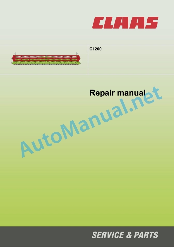
Claas F1200 C1200 Soja Getreide Lexion (442) Combines Repair Manual EN
$300.00
- Model: F1200 C1200 Soja Getreide Lexion (442) Combines
- Type Of Manual: Repair Manual
- Language: EN
- Format: PDF(s)
- Size: 15.4 MB
File List:
00 0295 260 0.pdf
00 0295 260 0.pdf:
Contents
1 General Information
1.1 General
1.1.1 Introduction
1.2 Safety rules
1.2.1 Important notice
1.2.2 Identification of warning and danger signs
1.2.3 General safety and accident prevention regulations
1.2.4 Front attachment and trailers
1.2.5 Adjustment and maintenance work
1.2.6 First aid measures
1.2.7 Danger of injury due to escaping hydraulic liquid
1.3 General repair instructions
1.3.1 Reason of damage
1.3.2 Spare parts
1.3.3 Gearboxes
1.3.4 Tensioning the steel roller chains
1.3.5 Taper ring fasteners
1.3.6 Self-locking bolts with micro-encapsulated adhesive
1.3.7 Liquid locking compound
1.3.8 Lock collar bearings
1.3.9 Adapter sleeve bearing
1.3.10 Ferrule fittings on hydraulic lines
1.3.11 Progressive ring fittings on hydraulic lines
1.3.12 Taper fittings on hydraulic lines
1.3.13 Hydraulic hoses
1.3.14 Welding Work
1.3.15 Some advice for speedy and correct repair work:
1.4 Torque settings
1.4.1 Tightening torques for metric standard threads
1.4.2 Tightening torques for metric fine threads
1.4.3 Tightening torques for hydraulic screw fittings with ferrule according to DIN 3861
1.4.4 Tightening torques for hydraulic screw fittings and air conditioner fittings with a sealing cone and O-ring DIN 3865
1.4.5 Tightening torques for hydraulic male connector DIN 3901
1.4.6 Tightening torques for direction-adjustable hydraulic male connectors ISO 6149-2 / ISO 11926-2 (3)
1.4.7 Tightening torque for hydraulic swivelling screw fittings
1.4.8 Tightening torques for hollow screws DIN 7643
1.4.9 Tightening torques for screw thread clamps
1.5 Specifications
1.5.1 Lubricants
2 Outputs / drives
2.1 Drive belts / drive chains
2.1.1 General warnings
2.1.2 Fixing material
2.1.3 Drive diagram
2.1.4 Removing belt (R1)
2.1.5 Removing belt (R1)
2.1.6 Adjusting belt (R1)
2.1.7 Removing chain (K6)
2.1.8 Installing chain (K6)
2.1.9 Adjusting chain (K6)
2.1.10 Removing chain (K9)
2.1.11 Installing chain (K9)
2.1.12 Adjusting chain (K9)
2.2 Front attachment drive universal drive shaft
2.2.1 Removing / disassembling the universal drive shaft
2.2.2 Universal drive shaft overview
2.2.3 Assembling / installing the universal drive shaft
2.2.4 Removing / disassembling the cam-type cut-out clutch
2.2.5 Cam-type cut-out clutch overview
2.2.6 Assembling / installing the cam-type cut-out clutch
2.3 Front attachment drive intermediate drive shaft
2.3.1 Removing / disassembling the intermediate drive shaft
2.3.2 Intermediate drive shaft – Overview
2.3.3 Assembling / installing the intermediate drive shaft
2.4 Knife drive
2.4.1 Drive pulley of belt (R1) – Overview
2.4.2 Removing drive pulley of belt (R1)
2.4.3 Installing the drive pulley of belt (R1)
2.4.4 Guide roller of belt (R1) – Overview
2.4.5 Removing the guide roller of belt (R1)
2.4.6 Installing the guide roller of belt (R1)
2.4.7 Overview of jockey pulley belt (R1)
2.4.8 Removing the jockey pulley of belt (R1)
2.4.9 Installing the jockey pulley of belt (R1)
2.4.10 Driven pulley of belt (R1) – Overview
2.4.11 Removing the driven pulley of belt (R1)
2.4.12 Installing the driven pulley of belt (R1)
2.4.13 Planetary gear – Overview
2.4.14 Removing the planetary gear
2.4.15 Disassembling the planetary gear
2.4.16 Assembling the planetary gear
2.4.17 Installing the planetary gear
2.5 Knife drive special tool
2.5.1 Removing drive pulley of belt (R1)
2.5.2 Disassembling the planetary gear
2.5.3 Assembling the planetary gear
2.6 Intake auger drive
2.6.1 Removing the drive sprocket of chain (K6)
2.6.2 Installing the drive sprocket of chain (K6)
2.6.3 Removing the driven sprocket of chain (K6)
2.6.4 Installing the driven sprocket of chain (K6)
2.6.5 Removing the drive shaft
2.6.6 Installing the drive shaft
2.6.7 Removing the outer intake auger bearing
2.6.8 Installing the outer intake auger bearing
2.6.9 Removing / disassembling the inner intake auger bearing
2.6.10 Assembling / installing the inner intake auger bearing
2.7 Special tools for intake auger drive
2.7.1 Removing the drive sprocket of chain (K6)
2.7.2 Removing the outer intake auger bearing
2.8 Reel drive
2.8.1 Removing the drive sprocket of chain (K9)
2.8.2 Installing the drive sprocket of chain (K9)
2.8.3 Removing the driven sprocket of chain (K9)
2.8.4 Installing the driven sprocket of chain (K9)
2.8.5 Removing the left flanged shaft of the left reel
2.8.6 Installing the left flanged shaft of the left reel
2.8.7 Removing the right flange of the left reel
2.8.8 Installing the right flange of the left reel
2.8.9 Removing the right flanged shaft of the right reel
2.8.10 Installing the right flanged shaft of the right reel
2.8.11 Removing the flanged shaft between the left and right reel
2.8.12 Installing the flanged shaft between the left and right reel
3 Hydraulic system
3.1 Valves
3.1.1 Solenoid valves – Overview
3.1.2 Removing solenoid valves
3.1.3 Installing solenoid valves
3.1.4 Non-return valves – Overview
3.1.5 Removing the non-return valves
3.1.6 Installing non-return valves
3.2 Special tools for valves
3.2.1 Removing solenoid valves
3.2.2 Installing solenoid valves
3.3 Motors
3.3.1 Removing the hydraulic reel drive motor (2012)
3.3.2 Installing the hydraulic reel drive motor (2012)
3.4 Cylinder
3.4.1 Removing the left reel height adjustment hydraulic cylinder (3015)
3.4.2 Left reel height adjustment hydraulic cylinder (3015) – Overview
3.4.3 Installing the left reel height adjustment hydraulic cylinder (3015)
3.4.4 Removing the centre reel height adjustment hydraulic cylinder (3136)
3.4.5 Centre reel height adjustment hydraulic cylinder (3136) – Overview
3.4.6 Installing the centre reel height adjustment hydraulic cylinder (3136)
3.4.7 Removing the right reel height adjustment hydraulic cylinder (3014)
3.4.8 Right reel height adjustment hydraulic cylinder (3014) – Overview
3.4.9 Installing the right reel height adjustment hydraulic cylinder (3014)
3.4.10 Removing the hydraulic fore and aft reel adjustment hydraulic cylinder (3016)
3.4.11 Hydraulic fore and aft reel adjustment hydraulic cylinder (3016) – Overview
3.4.12 Installing the hydraulic fore and aft reel adjustment hydraulic cylinder (3016)
3.4.13 Cutterbar table lock hydraulic cylinder (3137) – Overview
4 Electric / Electronic systems
4.1 Wiring looms / Sensors
4.1.1 Left Auto-Contour sensor band (B3) – Overview
4.1.2 Right Auto-Contour sensor band (B4) – Overview
4.1.3 Reel height position sensor (B39) – Overview
5 Crop pick-up
5.1 Reel
5.1.1 Removing the left reel
5.1.2 Installing the left reel
5.1.3 Removing the right reel
5.1.4 Installing the right reel
5.1.5 Replacing the cam rollers
5.1.6 Removing the control element of cam rollers
5.1.7 Installing the control element of cam rollers
5.1.8 Removing the control spider
5.1.9 Installing the control spider
5.1.10 Removing the reel spider
5.1.11 Installing the reel spider
5.1.12 Removing the bearing of the reel tine tubes
5.1.13 Installing the bearing of the reel tine tubes
5.1.14 Removing the reel tine tubes
5.1.15 Installing the reel tine tubes
5.1.16 Changing the reel tines
5.1.17 Installing the reel tine riveting nut
5.1.18 Removing the left reel shaft bearing
5.1.19 Installing the left reel shaft bearing
5.1.20 Removing / disassembling the centre reel shaft bearing
5.1.21 Assembling / installing the centre reel shaft bearing
5.1.22 Removing the right reel shaft bearing
5.1.23 Installing the right reel shaft bearing
5.1.24 Removing the outer reel support arm
5.1.25 Installing the outer reel support arm
5.1.26 Removing the centre reel support arm
5.1.27 Installing the centre reel support arm
5.1.28 Replacing the hydraulic fore and aft reel adjustment slide plates
6 Feeder unit
6.1 Intake auger
6.1.1 Removing the intake auger
6.1.2 Installing the intake auger
6.1.3 Removing intake auger fingers
6.1.4 Installing intake auger fingers
6.1.5 Removing the adjusting shaft
6.1.6 Installing the adjusting shaft
6.1.7 Removing the control shaft
6.1.8 Installing the control shaft
7 Mowing unit
7.1 Mower head
7.1.1 Removing the knives
7.1.2 Installing the knives
7.1.3 Adjusting knife clips
John Deere Repair Technical Manual PDF
John Deere Parts Catalog PDF
John Deere Tractors 7500 Parts Catalog CPCQ26568 30 Jan 02 Portuguese
John Deere Repair Technical Manual PDF
John Deere Repair Technical Manual PDF
John Deere Repair Technical Manual PDF
John Deere POWERTECH E 4.5 and 6.8 L Diesel Engines TECHNICAL MANUAL 25JAN08
John Deere Repair Technical Manual PDF
John Deere Repair Technical Manual PDF
John Deere Parts Catalog PDF
John Deere Tractors 6300, 6500, and 6600 Parts Catalog CQ26564 (29SET05) Portuguese
John Deere Repair Technical Manual PDF


