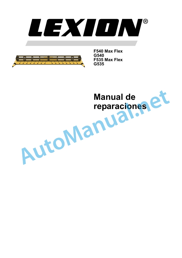
Claas F540-535 Maxflex G540-535 Cat (441) Combines Repair Manual ES
$300.00
- Model: F540-535 Maxflex G540-535 Cat (441) Combines
- Type Of Manual: Repair Manual
- Language: ES
- Format: PDF(s)
- Size: 15.3 MB
File List:
00 0295 886 0.pdf
00 0295 886 0.pdf:
1 CCN Statements
1.1 CCN (CLAAS Component Number = CLAAS component number)
1.1.1 General instructions
1.1.2 Electrical installation regulations
1.1.3 Hydraulic installation regulations
1. Introduction
1.1 General instructions
1.1.1 Manual handling
Texts and figures
Division with construction group structure
Search and find
Direction signs
1.1.2 Validity of instructions
1.2 General repair instructions
1.2.1 Technical data
1.2.2 Cause of the fault
1.2.3 Spare parts
1.2.4 Diesel engine
1.2.5 Gear
1.2.6 Three-phase generator
1.2.7 Welding work
1.2.8 Tensioning steel roller chains
1.2.9 Conical ring joints
1.2.10 Self-locking screws with microencapsulated glue
1.2.11 Liquid insurance for screws
1.2.12 Bearing with tension ring
1.2.13 Bearings with tension sleeve
1.2.14 Threaded joints with adjusting ring in hydraulic pipes
1.2.15 Threaded joints with progressive ring in hydraulic pipes
1.2.16 Threaded joints with sealing cone in hydraulic pipes
1.2.17 Hydraulic hoses
1.2.18 The repair is quick and correct, when the following is taken into account
1.3 Tightening torques
1.3.1 Tightening torques for metric regulation thread
1.3.2 Tightening torques for metric fine thread
1.3.3 Tightening torques for hydraulic screw connections with adjusting ring DIN 3861
1.3.4 Tightening torques for hydraulic screw connections and air conditioning screw connections with conical seal and toroidal seal DIN 3865
1.3.5 Tightening torques for hydraulic threaded fittings DIN 3901
1.3.6 Tightening torques for addressable hydraulic threaded fittings ISO 6149-2 / ISO 11926-2 (3)
1.3.7 Tightening torques for tilting threaded joints
1.3.8 Tightening torques for hollow screws DIN 7643
1.3.9 Tightening torques for brake line joints
1.3.10 Tightening torques for helical thread clamps
1.3.11 Tire tightening torques
1.4 Technical data
1.4.1 Lubricants
2 Security measures
2.1 General instructions
2.1.1 Especially important
2.1.2 Warning and danger signs
2.1.3 General prescriptions for safety and accident prevention
2.1.4 Headers and trailers
2.1.5 Adjustment and maintenance work
2.1.6 Risk of accident due to hydraulic fluid
2.1.7 First aid measures
3 Drives
3.1 Drive belts / drive chains
3.1.1 General warnings
3.1.2 Fixing material
3.1.3 Drive diagram
3.1.4 Remove the strap (R1)
3.1.5 Remove the strap (R1)
3.1.6 Adjust the belt (R1)
3.1.7 Dismantle the chain (K6)
3.1.8 Assemble the chain (K6)
3.1.9 Adjust the chain (K6)
3.1.10 Dismantle the chain (K9)
3.1.11 Assemble the chain (K9)
3.1.12 Adjust the chain (K9)
3.2 Spindle drive cardan shaft
3.2.1 Disassemble/dismantle the cardan shaft
3.2.2 Cardan shaft summary
3.2.3 Assemble/mount the cardan shaft
3.2.4 Disassemble/dismantle the cam switch clutch
3.2.5 Cam Switch Clutch Summary
3.2.6 Assemble/assemble the cam switch clutch
3.3 Spindle drive intermediate shaft
3.3.1 Disassemble/dismantle the intermediate shaft
3.3.2 Summary of the intermediate shaft
3.3.3 Assemble / assemble the intermediate shaft
3.4 Blade drive
3.4.1 Overview of belt drive pulley (R1)
3.4.2 Remove the belt drive pulley (R1)
3.4.3 Assemble the belt drive pulley (R1)
3.4.4 Deflection pulley, belt (R1), summary
3.4.5 Remove the belt deflection pulley (R1)
3.4.6 Install the belt deflection pulley (R1)
3.4.7 Tensioner pulley, belt (R1) summary
3.4.8 Remove the belt tensioner pulley (R1)
3.4.9 Install the belt tensioner pulley (R1)
3.4.10 Overview of belt driven pulley (R1)
3.4.11 Remove the belt driven pulley (R1)
3.4.12 Assemble the belt driven pulley (R1)
3.4.13 Overview of planetary gear
3.4.14 Disassemble the planetary gear
3.4.15 Disassemble the planetary gear
3.4.16 Assemble the planetary gear
3.4.17 Assemble the planetary gear
3.5 Special tool for operating the blades
3.5.1 Remove the belt drive pulley (R1)
3.5.2 Disassemble the planetary gear
3.5.3 Assemble the planetary gear
3.6 Drive of the feeding augers
3.6.1 Remove the chain drive sprocket (K6)
3.6.2 Install the chain drive sprocket (K6)
3.6.3 Remove the chain driven sprocket (K6)
3.6.4 Install the chain driven sprocket (K6)
3.6.5 Dismantle the drive shaft
3.6.6 Assemble the drive shaft
3.6.7 Remove the outer support of the feeding auger
3.6.8 Assemble the outer support of the feeding auger
3.6.9 Disassemble/dismantle the inner support of the feeding auger
3.6.10 Assemble / assemble the inner support of the feed auger
3.7 Special tool for feeding auger drive
3.7.1 Remove the chain drive sprocket (K6)
3.7.2 Remove the outer support of the feeding auger
3.8 Reel drive
3.8.1 Remove the chain drive sprocket (K9)
3.8.2 Install the chain drive sprocket (K9)
3.8.3 Remove the chain driven sprocket (K9)
3.8.4 Install the chain driven sprocket (K9)
3.8.5 Dismantle the shaft with left coupling plate from the left reel
3.8.6 Assemble the shaft with left coupling plate of the left reel
3.8.7 Remove the right flange from the left reel
3.8.8 Assemble the right flange of the left reel
3.8.9 Dismantle the shaft with right coupling plate from the right reel
3.8.10 Assemble the shaft with right coupling plate of the right reel
3.8.11 Dismantle the shaft with coupling plate between the left and right reel
3.8.12 Assemble the shaft with coupling plate between the left and right reel
4 Hydraulic installation
4.1 Valves
4.1.1 Summary of electromagnetic valves
4.1.2 Dismantle the electromagnetic valves
4.1.3 Assemble the electromagnetic valves
4.1.4 Overview of check valves
4.1.5 Dismantle the check valves
4.1.6 Assemble the check valves
4.2 Special valve tool
4.2.1 Dismantle the electromagnetic valves
4.2.2 Assemble the solenoid valve
4.3 Engines
4.3.1 Remove the hydraulic motor from the reel drive (2012)
4.3.2 Assemble the hydraulic motor for the reel drive (2012)
4.4 Cylinder
4.4.1 Dismantle the hydraulic cylinder of the left reel height adjustment (3015)
4.4.2 Summary of the left-hand reel height adjustment hydraulic cylinder (3015)
4.4.3 Assemble the hydraulic cylinder of the left reel height adjustment (3015)
4.4.4 Dismantle the hydraulic cylinder of the central adjustment of the height of the reel (3136)
4.4.5 Summary of the hydraulic cylinder of the central adjustment of the height of the reel (3136)
4.4.6 Assemble the hydraulic cylinder of the central adjustment of the height of the reel (3136)
4.4.7 Dismantle the hydraulic cylinder of the right reel height adjustment (3014)
4.4.8 Summary of the hydraulic cylinder of the right reel height adjustment (3014)
4.4.9 Assemble the hydraulic cylinder for the right reel height adjustment (3014)
4.4.10 Dismantle the hydraulic cylinder of the horizontal adjustment of the reel (3016)
4.4.11 Summary of the hydraulic cylinder for horizontal reel regulation (3016)
4.4.12 Assemble the hydraulic cylinder for the horizontal adjustment of the reel (3016)
4.4.13 Summary of cutting mechanism table lock hydraulic cylinder (3137)
5 Electrical installation / electronic installation
5.1 Cable trunks / sensors
5.1.1 Summary of the AUTO-CONTOUR left probe sensor (B003)
5.1.2 Sensor summary (B004) right probe of AUTO-CONTOUR
5.1.3 Sensor summary (B039) reel height position
6 Reception of the harvest
6.1 Windlass
6.1.1 Remove the left reel
6.1.2 Assemble the left reel
6.1.3 Remove the right reel
6.1.4 Assemble the right windlass
6.1.5 Change the drive pulleys
6.1.6 Remove the control from the control pulleys
6.1.7 Assemble the control of the control pulleys
6.1.8 Dismantling the control star
6.1.9 Assemble the control star
6.1.10 Remove the windlass star
6.1.11 Assemble the windlass star
6.1.12 Remove the reel spike tube support
6.1.13 Assemble the reel spike tube support
6.1.14 Dismantle the spike tubes from the reel
6.1.15 Assemble the reel spike tubes
6.1.16 Change the reel tines
6.1.17 Assemble the riveted nut of the reel tines
6.1.18 Remove the left reel support
6.1.19 Assemble the left reel support
6.1.20 Disassemble/dismantle the central support of the reel
6.1.21 Assemble / assemble the central support of the reel
6.1.22 Remove the right reel support
6.1.23 Assemble the right reel support
6.1.24 Dismantle the external support arm of the reel
6.1.25 Assemble the external support arm of the reel
6.1.26 Dismantle the central support arm of the reel
6.1.27 Assemble the central support arm of the reel
6.1.28 Change the sliding plates of the horizontal adjustment of the reel
7 Power set
7.1 Feed auger
7.1.1 Dismantle the feeding auger
7.1.2 Assemble the feeding auger
7.1.3 Dismantle the feeding auger fingers
7.1.4 Assemble feed auger fingers
7.1.5 Dismantle the adjustment shaft
7.1.6 Assemble the adjustment shaft
7.1.7 Dismantle the control shaft
7.1.8 Assemble the control shaft
8 Mowing device
8.1 Cutter bar
8.1.1 Remove the blades
8.1.2 Assemble the blades
8.1.3 Adjust guide plates
Alphabetical index
John Deere Repair Technical Manual PDF
John Deere Repair Technical Manual PDF
John Deere Parts Catalog PDF
John Deere Harvesters 8500 and 8700 Parts Catalog CPCQ24910 Spanish
John Deere Repair Technical Manual PDF
John Deere Repair Technical Manual PDF
John Deere Diesel Engines POWERTECH 2.9 L Component Technical Manual CTM126 Spanish
John Deere Repair Technical Manual PDF
John Deere Repair Technical Manual PDF
John Deere Application List Component Technical Manual CTM106819 24AUG20
John Deere Repair Technical Manual PDF
John Deere Repair Technical Manual PDF
John Deere PowerTech M 10.5 L and 12.5 L Diesel Engines COMPONENT TECHNICAL MANUAL CTM100 10MAY11


