Claas Frontloader 140C-40 C (B90) Tractors Technical System EN
$300.00
- Model: Frontloader 140C-40 C (B90) Tractors
- Type Of Manual: Technical System
- Language: EN
- Format: PDF(s)
- Size: 51.9 MB
File List:
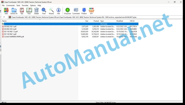
00 0302 343 1.pdf
00 0302 565 2.pdf
00 1143 962 1 2.pdf
00 1143 962 1.pdf
CLAAS HARNESS PARTS.pdf
00 0302 343 1.pdf:
PROFI CAM 3
Table of contents
General information
Marking of warnings and hazard prevention notes
First-aid measures
CCN explanation
CCN (CLAAS Component Number)
Electric system standard
Overview
Hydraulic system standard
Overview
CCN (CLAAS Component Number)
10 Electrical / Electronic equipment
1030 Board computer / Indicators
Camera system
Description of function
1097 Testing / Measuring / Adjusting
Testing / measuring / adjusting the PROFI CAM
Checking the fuse in the video channel select box (C102)
Testing the video camera connector (C055)
1098 Fault / remedy
Fault / remedy PROFI CAM
The video monitor (C101) shows no image or cannot be switched on (indicator light fails to light up)
Video monitor (C102) displays a blue image either permanently or temporarily
The video monitor image is blurred
Replacing the fuse in the video channel select box (C102)
Connection and connecting cable with video camera (C055)
00 0302 565 2.pdf:
Sensor system
Table of contents
CCN explanation
CCN (CLAAS Component Number)
Electric system standard
Overview
Hydraulic system standard
Overview
CCN (CLAAS Component Number)
Introduction
Safety rules
Safety and hazard information
10 Electrical / Electronic equipment
1097 Testing / Measuring / Adjusting
Test report of the angle sensor (0011780.x)
Application of test report
Required tools
Test report of the angle sensor (0011780.x)
Testing / Measuring / Adjusting of angle sensor (0011780.x)
1. Reason for test
2. Mechanical test of angle sensor
3. Electric test with CDS
4. Electric test with multimeter
5. Mechanical test of connecting cable
Completing the machine
Test report of position and speed sensors
Application of test report
Required tools
Sensor variants
Part numbers of speed sensors
Part number of position sensor
Test report of position and speed sensors
Testing / measuring / adjusting of position and speed sensors
1. Reason for test
2. Mechanical test
3. Electric test with CDS
4a. Installation dimensions
Check of installation dimension
Installation dimensions of gearbox speed sensor (0011 799.x) and cam speed sensor (0011 810.x)
Installation dimension of position sensor (0011 815.x)
4b. Installation position
Centring of sensor
Metal-free zone
5. Electric test with multimeter
Voltage measurement
Direction of rotation and speed sensor (0011 605.x)
Measured values table
6. Mechanical test of connecting cable
Completing the machine
Test report of the urea sensor (00 0773 207 x)
Application of test report
Required tools
Parts number of the urea sensor
Test report of the urea sensor
Testing / measuring / adjusting urea sensor
1. Reason for test
2. Mechanical test
3. Mechanical test of connecting cable
4. Electric test with multimeter
5. Component test with the CDS
00 1143 962 1 2.pdf:
FL – FLC loaders
Table of contents
Introduction
General Information
Document validity
Compatibility of FL front loaders and CLAAS tractors
Compatibility of FLC front loaders and CLAAS tractors
Technical specifications
Tightening torques (Nm)
Sectional view of machine
Front loader
2014 : FL
2014 : FLC
Components of the FL loader
Components of the FLC loader
Tool holder frame
“MX Master-Attach” tool holder frame
“Euro” tool holder frame
“MASTER-ATTACH/EURO” tool holder frame_x001D_/_x001C_SMS_x001D_-AL?3_x001D_ tool holder frame
_x001C_MASTER-ATTACH/FAUCHEUX-BLANC_x001D_ tool holder frame
Operation / Multifunction control lever
Description
_x001C_Propilot_x001D_ and _x001C_Flexpilot System_x001D_ control levers
CLAAS control lever
Hitch the machine
Hitching
The tractor approaches (Step 1)
The tractor engages (Step 2)
The tractor is engaged (Step 3)
Hitching the FL 250-60 front loader
Hitching the FLC front loader
MACH System – Description
Socket on loader side
Socket on tractor side
Loader difficult to hitch
Advice to make hitching easier
Unhitching the machine
Unhitching the FL250-60 front loader
Unhitching the FLC front loader
Loader difficult to unhitch
Hydraulic system
Hydraulic drive
Operation
Single and double action
Control valve slide valves
_x001C_Propilot System_x001D_
Description
Operation of the _x001C_Propilot System_x001D_ – Open Centre (OC)
Operation of the _x001C_Propilot System_x001D_ – Load sensing signal (LS)
“Flexpilot System”
Description
Operation of the “Flexpilotm” – Open Centre (OC)
Operation of the “Flexpilot System” – Load sensing signal (LS)
Hydraulic circuit diagrams
Lifting circuit – Operation
Lifting circuit of FL and FLC loaders
“Shock Eliminator System” (Option)
Loading circuit – Operation
Loading circuit of FL loaders
Hydraulic parallelogram – “PCH System”
Loading circuit of FLC loaders
3rd function circuit
Operating principle
Operation
4th function circuit
Operating principle
“Fast-Lock System” circuit
“Speed-Link System” circuit
Mechanical part
“ACS” circuit
“SCS” circuit
Faults and remedies
Faults on the “Mach System”
Appearance of oil leaks
Faults on “Propilot” and “Flexpilot System”
Open centre: Hydraulic malfunction noted on the tractor
Open centre: Loader does not lift the load malfunction noted on the tractor
Load sensing signal: Loader does not lift the load stated
Faults on “Flexpilot System”
Appearance of jerking relating to the hydraulic system
Abnormally hard to move the control lever
Control valve body rupturing under the effect of the pressure as soon as the vehicle is first switched on
Response time too long
Faults on lifting circuit
Loader lowering by itself
Faults on loading circuit
Loader dumping by itself
Lack of power when digging or unloading
Electric system
“Propilot” or “Flexpilot System” controls
4-function control lever (“Propilot” or “Flexpilot System”)
6-function control lever (“Propilot” or “Flexpilot System”)
Electrical wiring harness (“Propilot” or “Flexpilot System”)
Global view of the tractor wiring harness
ACS wiring harness (tractor side)
Safety wiring harness on the side)
“Mach system” wiring harness
ELIOS 230-210 wiring harness
AXOS 340-310 wiring harness
ARION 430-410 wiringg harness
Global view of the loader FL wiring harness
Wiring harness for loader equipped with 3rd function
Wiring harness for loader equipped with 3rd function and 4th function
Wiring harness for loader equipped with 3rd function, 4th function, ACS and “Fast-Lock” or “Speed-Link”
Wiring harness for loader equipped with 3rd function, 4th function, SCS, ACS and “Fast-Lock” or “Speed-Link”
Wiring harness for safety loader on the lifting and loading circuit
Global view of the loader FL C wiring harness
Wiring harness for loader equipped with 3rd function
Wiring harness for loader equipped with 3rd function and 4th function
Wiring harness for loader equipped with 3rd function, 4th function, aneed-Link”
Wiring harness for loader equipped with 3rd function, 4th function, SCS, ACS and “Fast-Lock” or “Speed-Link”
Wiring harness for safety loader ocircuit
Checking the loader solenoid valves
Characteristics of the solenoid valves
Dismantling the solenoid valve
Dismantling the solenoid valve of the 3rd function on the FL loader
User advice in order to avoid clogging the solenoid valves
Faults and remedies
Faults on the control lever
Option activated by a solenoid valve does not work
Solenoid valve not working
Maintenance
Maintenance advice
00 1143 962 1.pdf:
FL – FLC – FLE loaders
Table of contents
CCN explanation
CCN (CLAAS Component Number)
Electric system standard
Overview
Hydraulic system standard
Overview
CCN (CLAAS Component Number)
Introduction
General information
Using this diagnostic manual
Safety rules
Safety instructions and risk information
Validity of manual
Validity of this diagnostic manual
06 Lift device
0615 Front loader
Reminder
Control valve slide valves
Lifting circuit
“Shock Eliminator System” (Option)
Loading circuit
Loading circuit of FL loaders
Loading circuit of FLC – FLE loaders
Parallelogram hydraulic circuit
Hydraulic parallelogram – “PCH System”
3rd function circuit
Loading retarder
4th function circuit
Safety system circuit
“ACS” circuit
“SCS” circuit
“Fast-Lock System” circuit
“Speed-Link System” circuit
Mechanical part
0698 Problems / remedy
Faults on the Mach System
Appearance of oil leaks
Faults on Flexpilot System
Open centre: Hydraulic malfunction noted on the tractor
Open centre: Loader does not lift the load stated
Loaydraulic malfunction noted on the tractor
Load sensing signal: Loader does not lift the load stated
Faults on Flexpilot System
Appearance of jerking relating to the hydraulic system
Abnormally hard to move the control lever
Control valve body rupturing under the effect of the pressure asfirst switched on
Response time too long
Appearance of oil leaks outside the control valve
Faults on lifting circuit
Loader lowering by itself
Faults on loading circuit
Loader dumping by itself
Lack of power when digging or unloading
Checking the loader solenoid valves
Characteristics of the solenoid valves
Solenoid valve not working
Dismantling the solenoid valve
Dismantling the solenoid valve of the 3rd function on the FL loader
User advice in order to avoid clogging the solenoid valves
10 Electrical / Electronic equipment
1015 Wiring harnesses
Overview of the FL loader wiring harnesses
Wiring harness for loader equipped with 3rd function
Wiring harness for loader equipped with 3rd function and 4th function
Wiring harness for loader equipped with 3rd function, 4th function, ACS and “Fast-Lock” or “Speed-Link”
Wiring harness for loader equipped with 3rd function, 4th function, SCS, ACS and “Fast-LockasLink”
Wiring harness for safety loader on the lifting and loading circuit
Overview of the FLC loader wiring harnesses
Wiring harness for loader equipped with 3rd function
Wiring harness for loader equipped with 3rd function and 4th function
Wiring harness for loader equipped with 3rd function, 4th function, and “Fast-Lock”
Wiring harness for loader equipped with safety function on lifting and loading
Overview of FLE loader wiring harnesses
Wiring harness for loader equipped with 3rd function
Wiring harness for loader equipped with safety function on lifting and loading
Position of components
Hydraulic sysic cylinders
5000 Accumulators
8000 Couplings – Connections
Electric system
V Electronic components
X Connections
Y Electromagnetic coil
CLAAS HARNESS PARTS.pdf:
CLAAS HARNESS PARTS
Table of contents
10 Electrical / Electronic equipment
1081 Overview of connectors
CLAAS HARNESS PARP)
John Deere Parts Catalog PDF
John Deere Tractors 6300, 6500, and 6600 Parts Catalog CQ26564 (29SET05) Portuguese
John Deere Repair Technical Manual PDF
John Deere PowerTech M 10.5 L and 12.5 L Diesel Engines COMPONENT TECHNICAL MANUAL CTM100 10MAY11
John Deere Repair Technical Manual PDF
John Deere Application List Component Technical Manual CTM106819 24AUG20
John Deere Repair Technical Manual PDF
John Deere Repair Technical Manual PDF
John Deere Repair Technical Manual PDF
John Deere Parts Catalog PDF
John Deere Tractors 7500 Parts Catalog CPCQ26568 30 Jan 02 Portuguese
John Deere Repair Technical Manual PDF
New Holland Service Manual PDF

