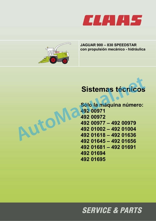
Claas Jaguar 900-830 (492) Forage Harvesters Technical System ES
$300.00
- Model: Jaguar 900-830 (492) Forage Harvesters
- Type Of Manual: Technical System
- Language: ES
- Format: PDF(s)
- Size: 14.9 MB
File List:
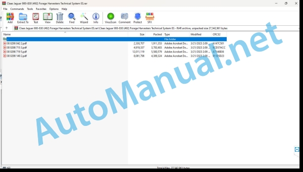
00 0290 042 2.pdf
00 0298 715 3.pdf
00 0298 719 5.pdf
00 0299 149 2.pdf
00 0290 042 2.pdf:
JAGUAR 900 – 810
CCN Explanation
CCN (CLAAS Component Number)
General indications
Electrical regulations
Hydraulic regulations
CCN (CLAAS Component Number)
Introduction
Manual validity
75 Central lubrication
7505 Container, pump
Central lubrication system plate switching – Jaguar type 491 / 492 / 493
Table of measured values
Function Description
7515 Lubrication/piping equipment
Connection diagram of the central lubrication system
92 Diagnosis
Error codes
Expanded table of CIS error codes (type 492, 493, 495)
00 0298 715 3.pdf:
Technical systems Hydraulic installation JAGUAR 900 – 830
1_x000B_Global hydraulic system
1.1 Hydraulic connection diagrams
1.1.1 JAGUAR 20/25 km/h from machine no. 492 01614
1.1.2 JAGUAR 20/25 km/h from machine no. 492 00133 – 492 01613
1.1.3 JAGUAR 20/25 km/h from machine no. 492 00011 – 492 00132
1.1.4 JAGUAR SPEEDSTAR/PROFISTAR with electrohydraulic advance
1.2 Valve supplements
1.2.1 Overview of valve supplements
1.2.2 Function of valve inserts
2_x000B_Hydraulic steering system
2.1 Hydraulic connection diagram
2.2 Diagram of the operation of the steering hydraulic system
2.2.1 Neutral
2.2.2 Use of address
2.3 Address Check
2.4 Autopilot electromagnetic valve
2.5 Check and measure
3_x000B_Operations hydraulic system
3.1 Hydraulic connection diagram
3.2 Main valve: circulation blocking valve, electromagnetic valve raise/lower the front implement
3.3 Valve combination with pressure retainer
3.4 Hitch electromagnetic valve
3.5 Sharpening solenoid valve, additional control 1, additional control 2
3.6 Regulation of Corn Cracker
3.7 Electromagnetic valve reversing the front implement (Y86)
3.8 Front implement motor, reversing drive (226)
3.9 Discharge Elbow, Swing Drive, Motor (206)
3.10 Head load switching valve (612)
3.11 Pressure retainer volume switching valve (Direct – Disc option)
3.12 Check and measure
4_x000B_Low pressure hydraulic system
4.1Hydraulic connection diagram
4.1.1 JAGUAR 20/25 km/h from machine no. 492 01614
4.1.2 JAGUAR 20/25 km/h from machine no. 492 00011 – 492 01613
4.1.3 JAGUAR SPEEDSTAR/PROFISTAR with electrohydraulic propulsion (EFA)
4.2 Position of the pieces
4.3 Electromagnetic valve (3/2 ways)
4.4 Pressure limiting valve
4.5 Hydraulic cylinder hooking the front implement (352)
4.6 Hydraulic cylinder gear lever lock
4.7 Flow regulating valve, suction arm drive
4.8 Suction arm drive, motor (228)
4.9 Pipe collector
4.10 Blade support valve cylinder
4.11 Check and measure
5_x000B_Hydraulic propulsion system
5.1 JAGUAR 20/25 km/h from machine no. 492 01614
5.1.1 Propulsion hydraulic system connection diagram
5.1.2 Diagram: draft force (F) / walking speed (v)
5.1.3 Propulsion function
5.1.4 Check and measure
5.1.5 Remove air from the motive pressure circuit, HPV pump / HMV motor
5.2 JAGUAR 20/25 km/h from machine no. 492 01613
5.2.1 Propulsion hydraulic system connection diagram
5.3 JAGUAR 20/25 km/h from machine no. 492 00011 to machine no. 492 00132
5.3.1 Propulsion hydraulic system connection diagram
5.4 JAGUAR SPEEDSTAR/PROFISTAR with electrohydraulic operation (EFA)
5.4.1 Propulsion hydraulic system connection diagram
5.4.2 Propulsion regulation
5.4.3 Parts
5.4.3.1 Propulsion adjustment pump (211)
5.4.3.2 Electromagnetic coil: Y141, Y142, Y143
5.4.3.3 Propulsion adjustment motor (210)
5.4.3.4 Propulsion valve, additional supply (757)
5.4.3.5 Bypass type valve, propulsion, filter
5.4.3.6 Switch B97 and B98
5.4.3.7 Pipe Manifold (807)
5.4.3.8 Venturi tube
5.4.4 Diagram: draft force (F) / walking speed (v)
5.4.5 Check and measure
6_x000B_Anti-vibration
6.1 Form of action
6.2 Management
6.2.1 Determine the central vibration axis
6.2.2 Activate anti-vibration
6.3 Sensors
6.4 Function
7_x000B_Compressed air installation
7.1 Trailer brake system connection diagram
7.2 Engine restrictor / pneumatic clutch connection diagram
0298 715.3
00 0298 719 5.pdf:
JAGUAR 900 – 830 (Type 492) JAGUAR 900 – 830 Profistar (Type 492) JAGUAR 900 – 830 Speedstar* (Type 492) (*with electrohydraulic advance)
Connection diagram configuration
I content
Distribution panel
Electrical panel 014 171.2 – up to machine no. 492-0132
Electrical panel 014 183.0 – from machine no. 492-0133 to machine no. 492-1605
Electrical panel 014 183.1 – from machine no. 492-1606
Module occupancy
Module A6 – Automatic air conditioning system
Module A7 – Cabin fan, speed regulator
Module A9 – AUTOPILOT (ATP)
Module A10 – On-Board Reporter (CAB)
Module A11 – CONTOUR
Module A14 – Control of feeding devices
Module A15 – Daimler-Chrysler (DC) electronic engine control
Module A17 – Adaptation of the ADM Daimler-Chrysler (DC) engine
Module A24 – Bedknife sharpening/adjustment (GGS)
Module A24 – Bedknife sharpening/adjustment (GGS)
Module A31 – Ejector tube control
Module A49 – Advance (EFA)
Module A53 – Adaptation (FEM) ISO – BUS
Module A54 – Ground Performance Measurement (FEM)
Module A73 – Discharge/silage material control (KDS) Option
Error List (CIS)
CIS error codes – table Jaguar models type 492 and 493
Connection diagrams 01a – 43a
01a – Main power supply, starter motor, reverse horn to machine no. 492-1605
01b – Main power supply, starter motor, reverse horn from machine no. 492-1606
02a – Start the diesel engine, regulation of the diesel engine revolutions not valid for Profistar, not valid for Speedstar (with electrohydraulic advance)
02b – Start the diesel engine, adjust the diesel engine speed – valid for Profistar with DC OM 502 diesel engine, valid for Speedstar (with electrohydraulic advance) with DC OM 502
02c – Start the diesel engine, regulation of the diesel engine revolutions valid for Profistar with DC OM 457 diesel engine, valid for Speedstar with electrohydraulic advance) with DC OM 457
03a – Diesel engine operational control
03b Diesel engine control – in diesel engines according to TIER 3 exhaust gas regulations
04a – Switching for road circulation, circulation shut-off valve to machine no. 492-1605
04b – Switching for road traffic, circulation shut-off valve from machine no. 492-1606
05a – Terminal, keyboard
06a – CAN-Bus, power supply for modules up to machine no. 492-1605
06b – CAN bus, power supply of modules from machine number 492 – 1606, not for Profistar, not for Speedstar (with electro-hydraulic drive
06c – CAN-Bus, power supply of the modules for Profistar, for Speedstar (with electro-hydraulic propulsion
07a – Main transmission to machine nr. 492-1605
07b – Main transmission from machine no. 492-1606
07c Main transmission from machine no. 49203523
09a – Device for sharpening, without automatic regulation of the bed knife up to machine no. 492-0132
09b – Sharpening device, with automatic regulation of the counterblade up to machine no. 492-0133
09c – Sharpening device, with automatic regulation of the bedknife up to machine no. 492-0132
09d – Sharpening device, with automatic regulation of the counterblade from machine no. 492-0133, service by potentiometer for preselection of sharpening cycles (R21)
09e – Sharpening device, with automatic regulation of the counterblade, service through CIS terminal (A30)
10a – Automatic regulation of the service bedknife using the potentiometer for preselection of the bedknife distance (R9)
10b – Automatic regulation of the service counterblade using the CIS terminal (A30)
11a – CORN-CRACKER adjustment
12a – Blade holder
13a – Automatic ejector tube rotation device
13b – Automatic rotation of the discharge elbow with the option module A73 control of discharge/silage material
14a – Rotate the ejector tube, raise/lower the ejector tube
15a – Near/Far Discharge Deflector
17a – Head drive, metal detector
18a – Stone detector
19a – Reel variator
20a – Raise/lower the headstock – without transversal adjustment
20b – Raise/lower the headstock – with transversal adjustment
21a – Additional hydraulic control 1 – fold the head, raise/lower the pressure roller or the reel
21b – Additional hydraulic control 2 – horizontal adjustment of the reel, additional hydraulic control for hitch type hitch
24a – CONTOUR / AUTOCONTOUR anti-vibration
25a – Direct Disc, speed control
26a – Functional control of the machine – up to machine no. 492-1914
26b – Functional control of the machine from machine number 492-1916, not valid for Profistar, not valid for Speedstar (with electrohydraulic advance)
26c – Functional control of the machine valid for Profistar, valid for Speedstar (with electrohydraulic advance)
26d Functional control of the machine valid for Profistar, valid for Speedstar with electrohydraulic advance) from machine no. 49205323
27a – Quantimeter (FEM)
28a – AUTOPILOT – with probes – up to machine no. 492-0132
28b – AUTOPILOT – with probes – from machine no. 492-0133
28c – AUTOPILOT-LASER – up to machine no. 492-0132
28d – AUTOPILOT-LASER – from machine no. 492-0133
29a – 4-wheel drive, central lubrication equipment, servo-assisted gear change
31a – Installation of turn signals, Europe
31b – Installation of turn signals, USA
32a – Main lighting switching, rear lights, position lights
33a – Low beam, high beam, rotating flashing light – without additional headlight
33b – Low beam, high beam, rotating flashing light – with additional headlight
34a – Work lights I
34b – Work lights II
35a – Horn, brake lights
36a – Instrument lighting, radio, rearview mirror adjustment
37a – Windshield wipers, window washer system – with clockwise rotating wipers
37b – Windshield wipers, window washer installation with right-hand rotation windshield wipers, left-hand rotation
38a – Air conditioning equipment
38b – Automatic air conditioning system
39a – Silage additive equipment – up to machine no. 492-0132
39b – Silage additive equipment – from machine number 492 – 0133
39c – Silage system with option module A73 control of discharge / silage material (adjustable pump in the water tank)
40a – Additional socket boxes, fuse tester
42a – Installation of trailer brakes on the Speedstar (with electrohydraulic advance)
43a – Electrohydraulic Advance (EFA)
Component Grid
Index in alphabetical order
0298 719.5
00 0299 149 2.pdf:
JAGUAR 900 • 830 SPEEDSTAR with mechanical – hydraulic propulsion, Technical systems
Hydraulic installation
Hydraulic connection diagram
Propulsion adjustment pump
Valve shorted (747)
HMV 210 propulsion adjustment motor
Electromagnetic valve (Y102)
Valve block
Electromagnetic valve / Propulsion brake valve
Assisted shift electromc valve
Lock cylinder (359)
Shift gears
Anti-vibration
Functioning
Electrical installation
1b – Power supply to the main voltage system, diesel engine start, reversing horn
2b – Start the diesel engine, adjustment of the diesel engine revolutions, protection of the propulsion revolutions
13a – Automatic rotation of the discharge elbow on the JAGUAR SPEEDSTAR
14b – Rotate the discharge elbow, raise/lower the discharge elbow
20a – Raise/lower the front implement, anti-vibration Jaguar Speedstar
24a – CONTOUR System
29b – Four-wheel drive, Central lubrication system, Power shift on the Jaguar SPEEDSTAR
35b – Horn, Brake light, Propulsion brake valve
39a – Silage system from machine nr. 492-0133
0299 149.2
John Deere Repair Technical Manual PDF
John Deere Repair Technical Manual PDF
John Deere Repair Technical Manual PDF
John Deere Parts Catalog PDF
John Deere Tractors 6300, 6500, and 6600 Parts Catalog CQ26564 (29SET05) Portuguese
John Deere Repair Technical Manual PDF
John Deere Application List Component Technical Manual CTM106819 24AUG20
John Deere Repair Technical Manual PDF
John Deere 18-Speed PST Repair Manual Component Technical Manual CTM168 10DEC07
John Deere Repair Technical Manual PDF
John Deere POWERTECH E 4.5 and 6.8 L Diesel Engines TECHNICAL MANUAL 25JAN08
John Deere Repair Technical Manual PDF
John Deere Repair Technical Manual PDF
John Deere Diesel Engines PowerTech 4.5L and 6.8L – Motor Base Technical Manual 07MAY08 Portuguese
John Deere Repair Technical Manual PDF

