Claas Jaguar 900-830 (493) Forage Harvesters Technical System FR
$150.00
- Model: Jaguar 900-830 (493) Forage Harvesters
- Type Of Manual: Technical System
- Language: FR
- Format: PDF(s)
- Size: 29.6 MB
File List:
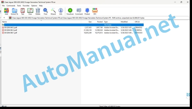
00 0290 040 2.pdf
00 0294 082 2.pdf
00 0294 086 1.pdf
00 0290 040 2.pdf:
JAGUAR 900 – 810
Contents
CCN explanation
CCN (CLAAS Component Number)
Electrical standard
Overview
Hydraulic standard
Overview
CCN (CLAAS Component Number)
Introduction
Validity of the notice
75 Central lubrication system
7505 Tank / Pump
Coupling of the central lubrication system plate – Jaguar types 491 / 492 / 493
Measurement value table
Function description
7515 Pipes
Central lubrication system connection diagram
92 Diagnosis
Error codes
CIS error code table (types 492, 493, 495)
00 0294 082 2.pdf:
Contents
1 Introduction
Structure of the Electrical Documentation
Connection diagram
Grid coordinates
List of bindings
CLAAS standardization:
2 Main electrical system
Overview
Top view
Bottom view
Electronic components
3 Modules
Representation of modules
Overview 1
Overview 2
Representation of modules
Module A6 – Automatic air conditioning
Module A7 – cabin ventilation speed regulator
Module A9 – Autopilot
Module A10 – On-board informant (CAB)
Module A11 – Outline
Module A14 – Power supply control
Module A15 – Electronic control of the DC motor
Module A17 – Motor adaptation (ADM)
Module A24 – Counter-knife sharpening/adjustment (GGS)
Module A30 – CIS terminal
Module A49 – Transmission Module
Module A53 – Adaptation (FEM) ISO – Bus
Module A54 – Performance measurement by site (FEM)
Module A73 – Silage additive ejection/control
Module A76 – Metal detector
4 Connection diagrams
01a Main power supply, diesel engine starter, reversing horn
Connection diagram (DIN A3)
Designations
Table of measured values
Description of operation
Sheet allocation
List of bindings
02a start diesel engine, adjust diesel engine speed
Connection diagram (DIN A3)
Designations
Table of measured values
Description of operation
Sheet allocation
List of bindings
03a Diesel engine monitoring
Connection diagram (DIN A3) up to machine No. 49300020 diesel engine exhaust gas standard TIER 2
Designations
Table of measured values
Description of operation
Sheet allocation
List of bindings
03b diesel engine monitoring
Connection diagram (DIN A3) from machine No. 49300021 diesel engine exhaust gas standard TIER 3
Designations
Table of measured values
Description of operation
Sheet allocation
List of bindings
04a Road travel switching, circuit shut-off valve
Connection diagram (DIN A3)
Designations
Table of measured values
Description of operation
Sheet allocation
List of bindings
05a – Terminal, keys
Connection diagram (DIN A3)
Designations
Description of operation
Sheet allocation
List of bindings
06a CAN bus
Connection diagram (DIN A3)
Designations
Table of measured values
CAN BUS network
Measured value table 50 kB vehicle CAN BUS (CLAAS CAN bus)
Measured value table J1939 CAN BUS
Measured value table ISO 11783 CAN BUS
Description of operation
Sheet allocation
List of bindings
07a Main drive
Connection diagram (DIN A3)
Designations
Table of measured values
Description of operation
Sheet allocation
List of bindings
09a Sharpening device without automatic counter-knife adjustment
Connection diagram (DIN A3)
Designations
Table of measured values
Description of operation
Sheet allocation
List of bindings
09b Sharpening device with automatic counter-knife adjustment
Connection diagram (DIN A3)
Designations
Table of measured values
Description of operation
Sheet allocation
List of bindings
10a Automatic counter-knife adjustment
Connection diagram (DIN A3)
Designations
Table of measured values
Description of operation
Sheet allocation
List of bindings
11a – Adjusting the Corn Cracker
Connection diagram (DIN A3)
Designations
Table of measured values
Description of operation
Sheet allocation
List of bindings
13a Automatic pivoting of the ejection chute
Connection diagram (DIN A3)
Designations
Table of measured values
Description of operation
Sheet allocation
List of bindings
14a – Pivoting of the chute, raising/lowering of the chute
Connection diagram (DIN A3)
Designations
Table of measured values
Description of operation
Sheet allocation
List of bindings
15a – Adjustable near/far ejection deflector
Connection diagram (DIN A3)
Designations
Table of measured values
Description of operation
Sheet allocation
List of bindings
17a Metal detector front tool drive
Connection diagram (DIN A3)
Designations
Table of measured values
Description of operation
Sheet allocation
List of bindings
17b Metal detector front tool drive
Connection diagram (DIN A3)
Designations
Table of measured values
Description of operation
Sheet allocation
List of bindings
18a Stone detector
Connection diagram (DIN A3)
Designations
Table of measured values
Description of operation
Sheet allocation
List of bindings
19a – Reel variator
Connection diagram (DIN A3)
Designations
Table of measured values
Description of operation
Sheet allocation
List of bindings
20a Raising/lowering of the front tool, with transverse regulation
Connection diagram (DIN A3)
Designations
Table of measured values
Description of operation
Sheet allocation
List of bindings
21a Additional distributor 1 – raising/lowering of the roller equalizer, raising/lowering of the reel
Connection diagram (DIN A3)
Designations
Table of measured values
Description of operation
Sheet allocation
List of bindings
21b – Additional distributor 2 – horizontal adjustment of the reel, towing hook, additional distributor for the Hitch towing hook
Connection diagram (DIN A3)
Designations
Table of measured values
Description of operation
Sheet allocation
List of bindings
24a Contour / Autocontour, oscillation damping
Connection diagram (DIN A3)
Designations
Table of measured values
Description of operation
Sheet allocation
List of bindings
25a Direct Disc / RPM monitoring
Connection diagram (DIN A3)
Designations
Table of measured values
Description of operation
Sheet allocation
List of bindings
26a Machine monitoring
Connection diagram (DIN A3)
Designations
Table of measured values
Description of operation
Sheet allocation
List of bindings
27a – Quantimeter (FEM)
Connection diagram (DIN A3)
Designations
Table of measured values
Description of operation
Sheet allocation
List of bindings
28a Autopilot – sensor system
Connection diagram (DIN A3)
Designations
Table of measured values
Description of operation
Sheet allocation
List of bindings
28b Autopilot – Laser
Connection diagram (DIN A3)
Designations
Table of measured values
Description of operation
Sheet allocation
List of bindings
29a – 4-wheel drive, centralized lubrication circuit, servo control
Connection diagram (DIN A3)
Designations
Table of measured values
Description of operation
Sheet allocation
List of bindings
31a – European flashing device
Connection diagram (DIN A3)
Designations
Table of measured values
Description of operation
Sheet allocation
List of bindings
31b – Flashing device USA
Connection diagram (DIN A3)
Designations
Table of measured values
Description of operation
Sheet allocation
List of bindings
32a – Main control of lights, rear lights, position light
Connection diagram (DIN A3)
Designations
Table of measured values
Description of operation
Sheet allocation
List of bindings
33a Low beam, main beam, rotating beacon
Connection diagram (DIN A3)
Designations
Table of measured values
Description of operation
Sheet allocation
List of bindings
34a Work lighting 1
Connection diagram (DIN A3)
Designations
Table of measured values
Description of operation
Sheet allocation
List of bindings
34b Work lighting 2
Connection diagram (DIN A3)
Designations
Table of measured values
Description of operation
Sheet allocation
List of bindings
35a – Audible warning, brake light
Connection diagram (DIN A3)
Designations
Table of measured values
Description of operation
Sheet allocation
List of bindings
36a – Instrument lighting, radio, mirror adjustment
Connection diagram (DIN A3)
Designations
Description of operation
Sheet allocation
List of bindings
37a windshield wiper, windshield washer system
Connection diagram (DIN A3)
Designations
Description of operation
Sheet allocation
List of bindings
38a Refrigerant system compressor
Connection diagram (DIN A3)
Designations
Table of measured values
Description of operation
Sheet allocation
List of bindings
38b Automatic air conditioning
Connection diagram (DIN A3)
Designations
Table of measured values
Description of operation
Sheet allocation
List of bindings
39a Additive device for silage
Connection diagram (DIN A3)
Designations
Table of measured values
Description of operation
Sheet allocation
List of bindings
40a Complementary female connectors, fuse checker
Connection diagram (DIN A3)
Designations
Description of operation
Sheet allocation
List of bindings
42a Trailer braking circuit
Connection diagram (DIN A3)
Designations
Description of operation
Sheet allocation
List of bindings
43a – electrohydraulically controlled hydrostatic transmission (EFA)
Connection diagram (DIN A3)
Designations
Table of measured values
Description of operation
Sheet allocation
List of bindings
5 Diagnosis
SFH error list sorted by error number
CIS Jaguar Types 492 and 493 error code table
6 Position of parts
Overview (DIN A3)
Representation
Alphabetical index
00 0294 086 1.pdf:
1 Complete hydraulic system
Tier 2 diesel engine / without cooling circuit pump
Hydraulic diagram
Designations
Screw for relieving the prestressing of the working hydraulics
Tier 3 diesel engine / with cooling circuit pump
Hydraulic diagram
Designations
Screw for relieving the prestressing of the working hydraulics
2 Steering hydraulics
Steering without Autopilot
Steering connection diagram without Autopilot
Designations
Steering with Autopilot
Steering connection diagram with Autopilot
Designations
Autopilot valve block
Designations
Description of operation
Neutral function diagram
Designations
Description of operation
Actuated steering function diagram
Designations
Description of operation
Check and measure
Description of operation
Check the steering system
Description of operation
3 Working hydraulics
Hydraulic diagram
Working hydraulic diagram
Designations
Main valve: cut-off valve, front tool up/down
Designations
Description of operation
Valve combination of ejection elbow / ejection flap with pressure accumulator
Designations
Description of operation
Tow hook solenoid valve
Designations
Description of operation
Grinding solenoid valve, auxiliary valve 1, auxiliary valve 2
Designations
Description of operation
Corn Cracker
Designations
Adjustment and purging
Ejection Elbow Swing Drive Motor
Designations
Front implement load switching valve
Designations
Description of operation
Pressure accumulator volume switching valve (Direct-Disc option)
Designations
Description of operation
Oscillation damping
Function
Description of operation
Check and measure
Measurement prerequisite
Setpoints
4 Low pressure hydraulics
Hydraulic diagram
Low pressure hydraulic system diagram
Designations
Four-wheel drive valve block, servo coupling, sharpening flap, front attachment reversing, front attachment clutch
Designations
Description of operation
Main drive valve block
Designations
Description of operation
Pressure limiter
Designations
Description of operation
Hydraulic cylinder for locking the control rod
Designations
Description of operation
Air purge
Flow limiter for suction arm drive
Designations
Description of operation
Suction arm drive motor
Designations
Pipe collector
Designations
Hydraulic components of the knife holder
Designations
Description of operation
Check and measure
Designations
Measurement condition
5 Supply hydraulics
Hydraulic feed drive, components
Designations
Main drive braked
Designations
Description of operation
ON main drive
Designations
Description of operation
Inversion
Designations
Description of operation
Power OFF
Designations
Description of operation
Designations
Description of operation
Quick stop
Designations
Description of operation
6 Advancement hydraulics
Complete connection diagram
Advance hydraulics system diagram
7 Compressed air circuit
Trailer brake system
Designations
Description of operation
Motor choke / compressed air coupling
Designations
Description of operation
Designations
Transmission regulation
Adjustment pump
Designations
Adjustment motor
Designations
Description of operation
High pressure sensor (B97, B98)
Designations
Description of operation
Check and measure
Checking pressures with high pressure sensors (B97, B98), pressure display on the CIS terminal
High pressure sensor measurement value table (B97, B89)
Function check
8 Position of parts
Painting
Components
John Deere Repair Technical Manual PDF
John Deere Repair Technical Manual PDF
John Deere Repair Technical Manual PDF
John Deere POWERTECH E 4.5 and 6.8 L Diesel Engines TECHNICAL MANUAL 25JAN08
John Deere Repair Technical Manual PDF
John Deere Repair Technical Manual PDF
John Deere Diesel Engines PowerTech 4.5L and 6.8L – Motor Base Technical Manual 07MAY08 Portuguese
John Deere Repair Technical Manual PDF
John Deere Repair Technical Manual PDF
John Deere Application List Component Technical Manual CTM106819 24AUG20
John Deere Repair Technical Manual PDF
John Deere 18-Speed PST Repair Manual Component Technical Manual CTM168 10DEC07
John Deere Repair Technical Manual PDF
John Deere Transmission Control Unit Component Technical Manual CTM157 15JUL05
John Deere Parts Catalog PDF
John Deere Tractors 6300, 6500, and 6600 Parts Catalog CQ26564 (29SET05) Portuguese


