Claas Jaguar 980-930 (497) Forage Harvesters Technical System ES
$150.00
- Model: Jaguar 980-930 (497) Forage Harvesters
- Type Of Manual: Technical System
- Language: ES
- Format: PDF(s)
- Size: 125 MB
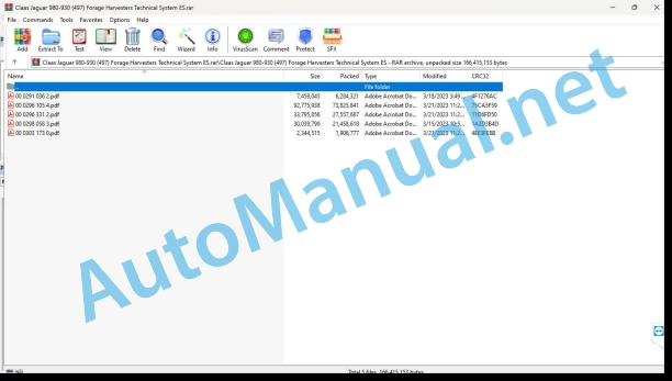
File List:
00 0291 036 2.pdf
00 0296 105 4.pdf
00 0296 331 2.pdf
00 0298 058 3.pdf
00 0303 173 0.pdf
00 0291 036 2.pdf:
MB OM460LAMB OM502LAMB OM906LAMB OM926LA
CCN Explanation
CCN (CLAAS Component Number)
General indications
Electrical regulations
Hydraulic regulations
CCN (CLAAS Component Number)
Introduction
Safety instructions
Safety measures and danger notices
Manual validity
Manual validity
01 Engine
0125 Fuel/injection system
PLD fuel/injection system
PLD injection system
Function Description
Conveyor phases of the insertable pump
Function Description
Insertable pump control
Function Description
Classification of insertable pumps
Example of identification plate for insertable pumps
Example breakdown of the insertable pump nameplate
Low fuel pressure measurement
special tool
Preparation of low fuel pressure measurement
Function Description
Measurement values, low fuel pressure (behind the fuel filter)
0155 Engine adjustment
Diesel engine control, diesel engine (MB TIER 3) TUCANO, JAGUAR
Table of measured values
Function Description
Diesel engine control, diesel engine (MB TIER 3) LEXION
Table of measured values
Function Description
Diesel engine control, diesel engine (MB TIER 4i) TUCANO, JAGUAR
Table of measured values
Function Description
Torque limitation in case of lack of urea
Function Description
Torque limitation in case of insufficient urea quality
Function Description
Limiting touch when timed out with system errors
Function Description
Diesel engine control, diesel engine (MB TIER 4i) LEXION
Table of measured values
Function Description
Torque limitation in case of lack of urea
Function Description
Torque limitation in case of insufficient urea quality
Function Description
Limiting touch when timed out with system errors
Function Description
0165 Exhaust gas aftertreatment
MB TIER 4i pressurized air system (LEXION, TUCANO)
Function Description
Air dryer with integrated pressure regulator
Function Description
MB TIER 4i pressurized air system (JAGUAR)
Function Description
Air dryer with integrated pressure regulator
Function Description
SCR system – urea heating and injection
Function Description
Combined urea fill level/temperature sensor
Function Description
urea pump unit
Function Description
Reduction catalyst temperature sensors
Function Description
Dosing unit
Function Description
NOx sensor
Function Description
Combined humidity and temperature sensor of the aspirated air
Function Description
10 Install. electrical/electronic
1012 Modules / sensors
Module Overview – MB (OM460LA, 502LA, 906LA, 926LA)
Denominations
Module A015 – electronic engine control (ECM) – MB TIER 4i
Denominations
Module assignment, socket X1
Plug X2, sheet 1 of 2, line 6 and V8 engine
Module assignment, plug X2 sheet 1 of 2
Plug X2, blade 2 of 2, motor line 6
Module allocation, plug X2, leaf 2 of 2, motor line 6
Plug X2, blade 2 of 2, V8 engine
Module assignment, socket X2, sheet 2 of 2, V8 engine
Module A017 – engine adaptation (ADM) – MB TIER 3
Denominations
Denominations
Module A017 – engine adaptation (ADM) – MB TIER 4i
Denominations
Denominations
Module A032 – Reduction Catalyst (SCR) – MB TIER4i
Denominations
Denominations
MB OM460LA Sensors
Figure sensors
MB 502LA Sensors
Figure sensors
MB Sensors OM 906LA, OM 926LA
Figure sensors
1085 Networks
BUS (CAN) system – engine and machine
Function Description
92 Diagnosis
Diagnosis according to fault codes
9220 Diesel Engine Error Codes (J1939)
FMI (Failure Mode Indicator) fault code
FMI fault code (Failure Mode Indicator)
General indications
FMI 00 (signal too large)
FMI 01 (signal too small)
IMF 02 (implausible signal)
FMI 03 (voltage too high)
FMI 04 (voltage too low)
FMI 05 (current too low)
FMI 06 (current too high)
FMI 07 (mechanical failure)
FMI 08 (frequency signal defective)
IMF 09 (communication failure)
FMI 10 (signal change too fast)
IMF 11 (multiple failure)
FMI 12 (defective ECU)
FMI 13 (signal outside calibration range)
IMF 16 (non-existent parameter)
FMI 17 (ECU not responding)
FMI 18 (power supply failure)
FMI 19 (software requirements not met)
IMF 95 (no signal change)
FMI 96 (CAN-Bus system defective)
IMF 97 (implausible state)
IMF 98 (warning)
IMF 99 (Info)
Error codes
Diesel Engine Fault Code List J1939 (MB)
Function Description
00 0296 331 2.pdf:
MAN D2868MAN D2862
CCN Explanation
CCN (CLAAS Component Number)
General indications
CCN (CLAAS Component Number)
Introduction
Safety instructions
Safety and hazard instructions
Manual validity
Manual validity
01 Engine
0125 Fuel/injection system
System Description
Systematic construction of the Common Rail system
high pressure pump
CP3.4 / CP3.4+ high pressure pump
ZME Metering Unit (MProp Fuel Proportional Valve) (Y332-MAN, Y356-MAN)
Occupation of the sockets
High pressure accumulator (rail)
Pressure limiting valve
Rail pressure sensor (B487-MAN, B514-MAN)
Sensor characteristic line
Occupation of the sockets
Injector (Y341-MAN, Y350-MAN)
Fuel temperature sensor (B197-MAN)
Occupation of the sockets
change image
0140 Exhaust gas system
Exhaust gas temperature sensor (B633-MAN)
Occupation of the sockets
0155 Engine adjustment
EDC7 control knob (A435-MAN, A570-MAN)
Control knob EDC7 C32 master CE (European Community) level IIIB/Tier 4i V8 (A435-MAN) motor plug pin assignment A
Control knob EDC7 C32 master CE (European Community) level IIIB/Tier 4i V8 (A435-MAN) vehicle plug pin assignment B
Control knob EDC7 C32 master CE (European Community) level IIIB/Tier 4i V8 (A435-MAN) injector plug pin assignment C
Control unit EDC7 C32 slave CE (European Community) level IIIB/Tier 4i V8 (A570-MAN) motor plug pin assignment A
Control unit EDC7 C32 slave CE (European Community) level IIIB/Tier 4i V8 (A570-MAN) vehicle plug pin assignment B
Control knob EDC7 C32 slave CE (European Community) level IIIB/Tier 4i V8 (A570-MAN) injector plug pin assignment C
Crankshaft speed sensor (incremental speed sensor) (B488-MAN)
Occupation of the sockets
change image
Camshaft speed sensor (segmented speed sensor) (B489-MAN)
Occupation of the sockets
change image
Oil pressure sensor (B104-MAN)
Sensor characteristic line
Occupation of the sockets
Fuel pressure sensor (B377-MAN)
Sensor characteristic line
Occupation of the sockets
Bosch LDF 6T intake pressure sensor (B623-MAN)
Occupation of the sockets
Coolant temperature sensor (B124-MAN)
Occupation of the sockets
change image
10 Install. electrical/electronic
1080 Electrical connection diagram
EDC7 Quick Reference Guide (D2862-V12)
EDC7 Quick Reference Guide (V8)
EDC7 Quick Reference Guide (R6)
DCU15 conveyor module quick reference guide (V motors)
DCU15 Conveyor Module Quick Reference Guide (Inline Motor)
90 Others
9090 Diagnostic
System structure, K-ducts, diagnostic sockets
Diagnostic socket (X200-MAN)
HD-OBD Diagnostic Socket (X200-MAN)
Error recording
CDS error indication
FMI (Failure Mode Identification)
SPN List EDC 7 (C32)
EDC7 C32 Check Step List (6 Cylinder Engine)
EDC7 C32 CE (European Community) Level IIIB/Tier 4i Check Step List (6-cylinder engine)
1. Measurements on the EDC7 C32 engine control unit
List of check steps EDC7 C32 master-slave CE (European Community) level IIIB/Tier 4i (8-cylinder V-engine)
1. Measurements on the EDC7 C32 engine control unit
Hydraulic Checklist
Basic information for troubleshooting
Catalog of questions in problematic cases
Common errors and instructions to solve them
General tips for troubleshooting in the fuel sector
Finding errors in the low pressure system
Finding errors in the high pressure system
Checking the amount of leaks
Measurement of the total amount of leaks
Preparations
Representation of the measurement construction principle
Checking individual injectors for leaks
High pressure pump conveying quantity measurement
Finding errors with CDS
Compression test
Acceleration test
Cylinder disconnection test
high pressure test
General fuel diagram high pressure pump greased with oil CP3.4 D2868
CP3.4 D2862 Oil Greased High Pressure Pump Fuel Scheme
D2868 Euro 4/5 engine fuel diagram
D2862 Euro 4/5 engine fuel diagram
Error finding plan
Bug finding program
General information
SPN 94 FUEL SUPPLY PRESSURE
SPN 100 physical OIL PRESSURE
SPN 102 INTAKE PRESSURE BEHIND THE RADIATOR (in the charge air pipe) physical
SPN 105 CHARGE AIR TEMPERATURE IN FRONT OF CYLINDER INLET (behind EGR) physical
SPN 108 physical ATMOSPHERIC PRESSURE
SPN 110 COOLING WATER TEMPERATURE physical
SPN 168 BATTERY VOLTAGE
SPN 171 SURROUNDING WATER TEMPERATURE physical
SPN 173 EXHAUST GAS TEMPERATURE BEFORE EXHAUST GAS FURTHER PROCESSING physical
SPN 174 FUEL TEMPERATURE physical
SPN 190 ENGINE RPM
Oscilloscope curves
SPN 609 PART CAN 1
SPN 651 BANK 1 INJECTOR 1 (6-cylinder engine: cylinder 1; 8-cylinder engine master: cylinder 1, slave: cylinder 5; 12-cylinder engine master: cylinder 1, slave: cylinder 12)
SPN 652 BANK 2 INJECTOR 1 (6-cylinder engine: cylinder 5; 8-cylinder engine master: cylinder 2, slave: cylinder 7; 12-cylinder engine master: cylinder 2, slave: cylinder 11)
SPN 653 BANK 1 INJECTOR 2 (6-cylinder engine: cylinder 3; 8-cylinder engine master: cylinder 3, slave: cylinder 6; 12-cylinder engine master: cylinder 3, slave: cylinder 10)
SPN 654 BANK 2 INJECTOR 2 (6-cylinder engine: cylinder 6; 8-cylinder engine master: cylinder 4, slave: cylinder 8; 12-cylinder engine master: cylinder 6, slave: cylinder 7)
SPN 655 BANK 1 INJECTOR 3 (6-cylinder engine: cylinder 2; 12-cylinder engine master: cylinder 5, slave: cylinder 8)
SPN 656 BANK 2 INJECTOR 3 (6-cylinder engine: cylinder 4; 12-cylinder engine master: cylinder 4, slave: cylinder 9)
SPN 1079 RAIL PRESSURE SENSOR SUPPLY
SPN 1080 SUPPLY TO THE LOW FUEL PRESSURE, INTAKE PRESSURE, OIL PRESSURE AND RELATIVE EXHAUST GAS PRESSURE SENSOR
SPN 1131 CHARGE AIR TEMPERATURE BEHIND THE RADIATOR (in the charge air pipe) physical
SPN 3004 EGR ACTUATOR PERMANENT ADJUSTMENT VARIATION
SPN 3007 INVALID DM4 REQUIREMENT
SPN 3009 EXCESSIVE ENGINE RPM
SPN 3014 MAIN RELAY LOCKED
SPN 3046 ATMOSPHERIC PRESSURE SENSOR
SPN 3063 INERTIA MOVEMENT NOT COMPLETED
SPN 3064 EDC STAND-ALONE OPERATION
SPN 3069 REDUNDANT RPM CONTROL
SPN 3076 STARTER LOCK RELEASE
SPN 3077 STARTER LOCK RELEASE
SPN 3082 OIL PRESSURE SENSOR PLAUSIBILITY
SPN 3083 PLAUSIBILITY OF THE RAIL PRESSURE SENSOR
SPN 3087 OIL PRESSURE SENSOR
SPN 3088 CHARGE AIR SENSOR BEHIND THE RADIATOR (in the charge air pipe)
SPN 3089 CHARGE AIR TEMPERATURE SENSOR IN FRONT OF CYLINDER INLET (behind EGR)
SPN 3091 COOLING WATER TEMPERATURE SENSOR
SPN 3097 FUEL TEMPERATURE SENSOR
SPN 3099 RAIL PRESSURE SENSOR
Sensor characteristic line
SPN 3100 FUEL PRESSURE SENSOR (LOW PRESSURE)
SPN 3671 ERROR READING EEPROM
SPN 3673 CAN PART 2 (OBD-CAN or master-slave-CAN)
SPN 3676 DEFECTIVE REDUNDANT PARKING DEVICE (INERTIA MOTION TEST)
SPN 3678 VOLTAGE BOOST CAPACITOR BANK 1
SPN 3679 VOLTAGE BOOST CAPACITOR BANK 2
SPN 3687 PRESSURE LIMITING VALVE DOES NOT OPEN
SPN 3732 DEFECT ASSESSMENT FOR INITIATION
SPN 3735 INTERNAL TEMPERATURE EDC
SPN 3736 TERMINAL DISCONNECTION BY EDC HARDWARE
SPN 3746 HIGHSIDE OUTLET STAGE EXHAUST GAS RETURN
SPN 3748 HIGHSIDE OUTPUT STAGE DOSING UNIT
SPN 3751 HIGHSIDE OUTPUT STAGE STARTER MOTOR RELAY (IMR)
SPN 3752 CAMSHAFT RPM SENSOR (SEGMENTED SENSOR)
SPN 3753 CRANKSHAFT RPM SENSOR (INCREMENTAL SENSOR)
Crankshaft speed sensor signal measured at 600 rpm between pin A73 and A55
SPN 3754 WATCHDOG SYSTEM BOOT ERROR
SPN 3755 PLAUSIBILIZATION OF LOW FUEL PRESSURE
SPN 3756 EGR RESPONSE SUPPLY VOLTAGE
SPN 3773 MASTER/SLAVE OPERATIONAL TYPE CHANGE FAILED
SPN 3775 RAIL PRESSURE CONTROL
SPN 3776 POSITIVE RAIL PRESSURE REGULATION DIFFERENCE
SPN 3777 NEGATIVE RAIL PRESSURE REGULATION DIFFERENCE
SPN 3778 RAIL PRESSURE: LEAKAGE UNDER PUSH CONDITIONS
SPN 3779 RAIL PRESSURE: LEAK DUE TO QUANTITY COMPENSATION
SPN 3780 RAIL PRESSURE: LARGE REGULATOR OUTPUT AT IDLE
SPN 3781 PRESSURE LIMITING VALVE OPEN
SPN 3782 DYNAMIC FUEL FEED PRESSURE
SPN 3785 PARTICULATE/CAT PM FILTER CONTROL
SPN 3786 PARTICULATE FILTER, TEMPERATURE LIMITS
SPN 3789 EXHAUST GAS DIFFERENTIAL PRESSURE SENSOR OR EXHAUST GAS RELATIVE PRESSURE SENSOR
SPN 3790 PLAUSIBILITY OF EXHAUST GAS DIFFERENTIAL PRESSURE OR RELATIVE EXHAUST GAS PRESSURE
SPN 3792 EXHAUST GAS TEMPERATURE SENSOR BEFORE EXHAUST GAS FURTHER PROCESSING
SPN 3793 EXHAUST GAS TEMPERATURE SENSOR AFTER EXHAUST GAS POST PROCESSING physical
SPN 3802 HIGHSIDE OUTLET STAGE PRESSURE AIR DISCONNECT VALVE
SPN 3804 CAN 1 TIMEOUT ERROR (FFR/MFR/EDC-CAN)
SPN 3806 CAN 2 TIMEOUT ERROR (OBD-CAN or master-slave-CAN)
SPN 3811 EXHAUST GAS TEMPERATURE PLAUSIBILIZATION BEFORE EXHAUST GAS FURTHER PROCESSING
SPN 3812 PLAUSIBILIZATION OF EXHAUST GAS TEMPERATURE AFTER EXHAUST GAS POST PROCESSING
SPN 3813 STARTER MOTOR MONITORING (starter motor protection)
SPN 3814 REGISTRATION OF THE DISCONNECTION TIME OF THE CONTROL CONTROLS
SPN 3819 PART CAN 3 (Exhaust Gas Post Processing CAN)
SPN 3820 CONTROL BYTE CAN 1
SPN 3821 CONTROL BYTE CAN 3 (Exhaust Gas Post Processing CAN)
SPN 3822 CONTROL TIMEOUT CAN 3 (exhaust gas post-processing CAN)
SPN 3836 PHYSICAL LAMBDA VALUE MEASUREMENT
Lambda probe socket assignment
SPN 3837 LAMBDA PROBE REGISTRATION
Lambda probe socket assignment
SPN 3838 INTERNAL RESISTANCE OF THE LAMBDA PROBE physical
Lambda probe socket assignment
SPN 3839 INTERNAL RESISTANCE OF THE LAMBDA PROBE
Lambda probe socket assignment
SPN 3844 PLAUSIBILIZATION OF THE CHARGE AIR TEMPERATURE IN FRONT OF THE CYLINDER INLET (behind EGR)
SPN 3847 CHARGE AIR TEMPERATURE BEHIND THE RADIATOR (in the charge air pipe)
SPN 3849 SCR CATALYST NOT MOUNTED (exhaust gas filter temperature plausibility)
SPN 3850 CLOSED EGR POSITION VARIATION
SPN 3851 EGR POSITION SENSOR (E-EGR)
SPN 3852 EGR PLAUSIBILIZATION THROUGH TEMPERATURE
SPN 3853 VARIATION OF THE PERMANENT E-EGR ADJUSTMENT
SPN 3855 LAMBDA PROBE SYSTEM
Lambda probe socket assignment
SPN 3856 LAMBDA PROBE CALIBRATION
Lambda probe socket assignment
SPN 3857 SPI COMMUNICATION LAMBDA PROBE
SPN 3858 LAMBDA PROBE TEMPERATURE
Lambda probe socket assignment
SPN 3859 LAMBDA PROBE TEMPERATURE, CALIBRATED
Lambda probe socket assignment
SPN 3863 THRUST CONTROL
SPN 3868 PLAUSIBILIZATION OF THE CHARGE AIR TEMPERATURE BEHIND THE RADIATOR (in the charge air pipe)
SPN 3919 NOx SENSOR HEATING ERROR STATUS
SPN 3920 NOx CONCENTRATION ERROR STATUS
SPN 3921 O2 CONCENTRATION ERROR STATUS
SPN 3927 LAMBDA PROBE NOT MOUNTED IN THE EXHAUST GAS PIPE
Lambda probe socket assignment
SPN 3929 EGR CONTROL WITH LAMBDA (MIL error)
SPN 3930 EGR CONTROL WITH LAMBDA (PR error)
SPN 3938 NON-ADAPTABLE LAMBDA PROBE
Lambda probe socket assignment
Location of components
Electrical installation
EDC7 control knob (A435-MAN, A570-MAN)
Description
Mounting location
high pressure pump
Description
Mounting location
ZME (MProp) Dosing Unit (Y332-MAN, Y356-MAN)
Description
Mounting location
High pressure accumulator (rail)
Description
Mounting location
Pressure limiting valve
Description
Mounting location
Rail pressure sensor (B487-MAN, B514-MAN)
Description
Mounting location
Injector (Y341-MAN, Y350-MAN)
Description
Mounting location
Crankshaft speed sensor (incremental speed sensor) (B488-MAN)
Description
Mounting location
Camshaft speed sensor (segmented speed sensor) (B489-MAN)
Description
Mounting location
Oil pressure sensor (B104-MAN)
Description
Mounting location
Fuel pressure sensor (B377-MAN)
Description
Mounting location
Bosch LDF 6T intake pressure sensor (B623-MAN)
Description
Mounting location
Coolant temperature sensor (B124-MAN)
Description
Mounting location
Exhaust gas temperature sensor (B633-MAN)
Description
Mounting location
00 0303 173 0.pdf:
JAGUAR 980 – 930Type 494JAGUAR 880 – 830Type 496JAGUAR 980 – 930Type 497JAGUAR 980 – 930Type 498
Introduction
Safety instructions
Safety and danger instructions
Manual validity
Manual validity
Security
General information
Warning and danger signs
security routines
First aid measures
62 Grain tank unloading
6298 Incident / Solution
Incident / Solution AUTO FILL
AUTO FILL, matrix of solutions for troubleshooting
AUTO FILL operation control
John Deere Repair Technical Manual PDF
John Deere Repair Technical Manual PDF
John Deere Repair Technical Manual PDF
John Deere Repair Technical Manual PDF
John Deere 16, 18, 20 and 24HP Onan Engines Component Technical Manual CTM2 (19APR90)
John Deere Repair Technical Manual PDF
John Deere Parts Catalog PDF
John Deere Tractors 6300, 6500, and 6600 Parts Catalog CQ26564 (29SET05) Portuguese
John Deere Repair Technical Manual PDF
John Deere Repair Technical Manual PDF
John Deere Repair Technical Manual PDF

