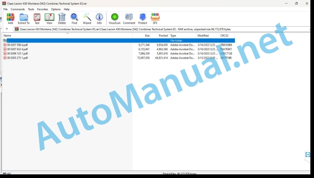
Claas Lexion 430 Montana (542) Combines Technical System ES
$150.00
- Model: Lexion 430 Montana (542) Combines
- Type Of Manual: Technical System
- Language: ES
- Format: PDF(s)
- Size: 80.3 MB
File List:
00 0297 598 4.pdf
00 0297 632 4.pdf
00 0299 125 1.pdf
00 0305 273 1.pdf
00 0299 125 1.pdf:
LEXION Montana 470-420 (Supplement)
Electrical installation – Index
Electrical panel on Montana 014 501.0 machines (with A50 RIO module)
Electrical panel on Montana 014 501.0 machines (with A45 HBM module)
Module occupancy
A35 Module – Montana Control, on Montana machines (with A50 RIO Module)
A35 Module – Montana Control, on Montana machines (with A45 HBM Module)
Module A36 – Montana gear preselection
Module A45 – Propulsion Hydraulic System Brake Restrictor (HBM)
A50 Module – RIO-Montana Module
Connection diagrams 01s – 42t
01s – Main voltage supply, diesel engine starter, on Montana machines
02s – Starting the diesel engine, regulating the speed of the diesel engine – on Montana machines
04s – Release for road circulation, circulation blocking valve of the operating hydraulic system, on Montana machines with ( module
04t – Release for road circulation, operation hydraulic system circulation block valve, on Montana machines with A45 module (HBM)
05s – Terminal, keyboard, rotary switch, printer, on Montana machines with A50 (RIO) module
05t – Terminal, keyboard, rotary switch, printer, on Montana machines with A45 module (HBM)
06s – CAN-BUS, module voltage supply, on Montana machines with A50 module (RIO)
06t – CAN-BUS, module voltage supply, on Montana machines with A45 module (HBM)
17s – Head drive, reversing the direction of travel, on Montana machines
20s – Raise/lower the headstock, transverse adjustment – on Montana machines
26s – Functional control of the machine, in Montana machines
41s – Axis control and headstock control, on Montana machines with A50 (RIO) module
41t – Axis control and headstock control, on Montana machines with A45 module (HBM)
42s – Control of the forward circuit and brakes, on Montana machines with A50 module (RIO)
42t – Control of the forward circuit and brakes, on Montana machines with A45 module (HBM)
Alphabetical index Electrical installation
Hydraulic installation – Index
1 Connection diagram General hydraulic installation
1.1 Connection diagram of the general hydraulic system LEXION-MONTANA 470 to machine no. 541 00023 / LEXION-MONTANA 430 to machine no. 542 00047
1.2 Connection diagram of the general hydraulic system LEXION-MONTANA 470 from machine no. 541 00024 / LEXION-MONTANA 430 from machine no. 542 00048
2 Hydraulic operating system
2.1 Connection diagram of the Montana LEXION-MONTANA 470 operating hydraulic system to machine no. 541 00023 / LEXION-MONTANA 430 to machine no. 542 00047
2.2 Connection diagram of the Montana LEXION-MONTANA 470 operating hydraulic system from machine no. 541 00024 / LEXION-MONTANA 430 from machine no. 542 00048
2.3 AUTO-CONTOUR (CAC) – transversal adjustment of the head
2.4 Reverse the direction of travel of the head
2.5 Cutting frame regulation
2.6 Cutting angle regulation
2.7 Service brake (fill brake retainer)
3 Axle hydraulic system
3.1 Connection diagram of the hydraulic system from the LEXION-MONTANA 470 axle to machine no. 541 00023 / LEXION-MONTANA 430 to machine no. 542 00047
3.2 Connection diagram of the hydraulic system of the LEXION-MONTANA 470 axle from machine no. 541 00024 / LEXION-MONTANA 430 from machine no. 542 00048
3.3 Circulation lock valve/pressure limiting valve of shaft drive
3.4 Hydraulic propulsion system brake restrictor control (HBM) only LEXION 470 up to machine. nr. 541 00023 / only LEXION 430 up to machine nr. 542 00047
3.5 Axle control – raise/lower axle, increase oil quantity
3.6 Gear shift assistant
3.7 Position of parts / control of the LEXION 470 axis to machine no. 541 00023 / LEXION 430 to machine no. 542 00047
3.8 Position of parts / control of the LEXION 470 axis from the machine. nr. 541 00024 / LEXION 430 from machine nr. 542 00048
4 Low pressure hydraulic installation
4.1 Connection diagram of the low pressure hydraulic installation
4.2 Electromagnetic valves of the low-pressure hydraulic system 3/2-way valve for differential lock, parking brake, 1st and 2nd gears
4.3 Hydraulic cylinder of the low pressure hydraulic system Differential lock
4.4 Position of the parts in the low pressure hydraulic installation Gearbox
5 Propulsion hydraulic system
5.1 Connection diagram of the hydraulic system of the Montana LEXION-MONTANA 470 propulsion to machine no. 541 00023 / LEXION-MONTANA 430 to machine no. 542 00047
5.2 Connection diagram of the hydraulic system of the Montana LEXION-MONTANA 470 propulsion from machine no. 541 00024 / LEXION-MONTANA 430 from machine no. 542 00048
5.3 Propulsion driving pressure
5.4 Motor unit Adjustment motor
5.5 Brake restrictor
Alphabetical index Hydraulic installation
299 125.0
John Deere Repair Technical Manual PDF
John Deere Repair Technical Manual PDF
John Deere Repair Technical Manual PDF
John Deere Repair Technical Manual PDF
John Deere Repair Technical Manual PDF
John Deere Repair Technical Manual PDF
John Deere Repair Technical Manual PDF
John Deere PowerTech M 10.5 L and 12.5 L Diesel Engines COMPONENT TECHNICAL MANUAL CTM100 10MAY11
John Deere Parts Catalog PDF
John Deere Tractors 6300, 6500, and 6600 Parts Catalog CQ26564 (29SET05) Portuguese
John Deere Repair Technical Manual PDF

