Claas Lexion 560-550 Montana (580) Combines Operator Manual ES
$50.00
- Model: Lexion 560-550 Montana (580) Combines
- Type Of Manual: Operator Manual
- Language: ES
- Format: PDF(s)
- Size: 76.6 MB
File List:
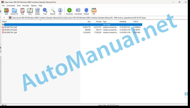
00 0293 784 7.pdf
00 0295 270 0.pdf
00 0299 764 1.pdf
00 0295 270 0.pdf:
1 Einleitung
1.1 Allgemeine Hinweise
1.1.1 Handling of the Anleitung
1.1.2 Gültigkeit der Anleitung
2 Vor Inbetriebnahme
2.1 Mähdrescher fahren mit mechanischer / elektro-hydraulischer Fahrbetätigung
2.1.1 Schaltvorgang EHS-Notbetrieb über Gang-Taster (ab Maschinen-Nr. …)
3 Wartung – Grundmaschine
3.1 Schmierstofftabellen
3.1.1 Schmierstoffe
4 Wartung Engine
4.1 Wartungstabellen
4.1.1 Wartungstabelle CATERPILLAR Engine
1 Introduction
1.1 General Information
1.1.1 How to use this manual
1.1.2 Validity of instructions
2 Prior to operation
2.1 Driving the combine with mechanical / electro-hydraulic ground drive control
2.1.1 EHS emergency operation shifting procedure using the gear touch sensor (from serial no. …)
3 Maintenance – Basic machine
3.1 Lubricants charts
3.1.1 Lubricants
4 Engine maintenance
4.1 Maintee sched
4.1.1 CATERPILLAR engine maintenance schedule
1 Introduction
1.1 General advice
1.1.1 Use of the notice
1.1.2 Validity of the notice
2 Avant la mise en service
2.1 Conduite de la moissonneuse-batteuse avec commande mécanique/électrohydraulique d’avancement
2.1.1 Processus de passage des vitesses en servicing de secaurs EHS au moyen de la touche rapport (à de la machine N˚ …)
3 Entretien – basic machine
3.1 Tableaux des lubricants
3.1.1 Lubricants
4 Engine maintenance
4.1 Tableaux d’entertien
4.1.1 CATERPILLAR engine maintenance table
1 Introduction
1.1 General indications
1.1.1 Application of the user manual
1.1.2 Validity of the user manual
2 Prima della messa in exercise
2.1 Advancement of the mietitrebbia with mechanical command / hydraulic electric
2.1.1 In this button you can start the EHS emergency using a button (from the machine No. …)
3 Maintenance – base machine
3.1 Lubricating tab
3.1.1 Lubricants
4 Motor maintenanc1 Maintenance tab
.1 CATERPILLAR engine maintenance table
1. Introduction
1.1 General instructions
1.1.1 Using the instructions
1.1.2 Validity of instructions
2 Before start-up
2.1 Driving the combine with a mechanical / electro-hydraulic feed drive
2.1.1 EHS gear changing process in emergency operation, using the gear button (from machine no. …)
3 Maintenance – Base machine
3.1 Lubricant tables
3.1.1 Lubricant
4 Engine maintenance
4.1 Maintenance tables
4.1.1 CATERPILLAR engine maintenance table
00 0299 764 1.pdf:
Introduction
Introduction
General instructions
Road traffic
Especially important
Identification plate / Serial number
Identification plate
Machine serial number
CATERPILLAR C-9/C-10 engine serial number
CATERPILLAR 3126 B engine serial number
Identification plate – straw chopper
Cabin serial number
Security measures
Security measures
Security support
Extinguisher
Battseparator switch
Place the shims
Hydraulic system
Risk of accident due to hydraulic fluid
Pressure retainers
Unload Auto-Contour Pressure Retainer
Unload the Autopilot pressure retainer
Unload Standard Spreader Pressure Retainer
Safety decals with warning symbols
Technical data
CLAAS LEXION 560 / 550 Montana
Front implements – weights, measurements
CLAAS LEXION 530 / 520 Montana
Front implements – weights, measurements
Safety devices
Before start-up
To be carried out before the first start-up
Cabin with automatic air conditioning system
Automatic air conditioning system
Control and information elements
Commissioning the automatic air conditioning system
Regulate cabin temperature
Manual regulation of the revolutions of the vaporizer fan
Start ECON operation
Turn off ECON operation
REHEAT operation (defogging the cabin windows)
Show outside temperature
Change the temperature display to ˚ Fahrenheit
Heaing of the foot area
Fault indication – error in temperature meter F0 (inside, blue)
Fault indication – error in temperature meter F1 (air release, yellow)
Fault indication – error in temperature meter F2 (outside, red)
Cabin with air conditioning installation (standard execution)
Put the air conditioning installation into service
Heating of the foot area
Reheat system (fogged windows)
Incident, possible causes and solutions – air conditioning
Refrigeration group (optional equipment)
Thermal bag (optional equipment)
Ice bucket (optional equipment)
Window washer equipment
Harvest control
Open or close the cabin roof
Driver’s platform
Driver platform box
Scorecard
Screen (preview screen)
Screen (crop screen)
Area C keys
Rotary switch D
Gradient system
Unevenness system control desk
Machine operation
Axle (wheel angle)
Cuttig mechanism
Axle (wheel angle) and cutting mechanism
Cutting mechanism adjustment key block (yellow)
Key block for axis adjustment (green)
Calibration
Inclinometer Calibration
Calibration of wheel cylinders
Cutting angle calibration
Transverse Tilt Calibration
Straw channel calibration (feed channel)
System information
Inclinoinfo
steering bar
ignition contact
Multifunctional switch
Central reporter
Multifunctional lever
Change the position of the steering bar
Adapt the top of the steering column
Adjust the height of the steering wheel
central electrical system
Driver’s seat
Driver’s seat, mechanical execution
Driver’s seat with air suspension (optional equipment)
Lighting and sockets
Advance lighting, work lights, mirrors
Sidefinder (optional equipment)
Wayfinder lighting
Position lights for excessive width
Access ladder
Ascent and widening of the staircase
Front staircase
Assemble the ladder
Fold up ladder steps
Turn the ladder
Back staircase
Other uses of the back staircase
Side covers
Open and close the side covers and tailgate
Open the tailgate
Adjust the height of the side cover handle
Adjust the side cover closure
Tool drawer
Fold the tool drawer
Mudguard
Install the fenders
steering axles
Adjustable drive steering axle (2.60 m – 3.20 m)
Change the adjustable steering axle 2.60 m – 3.20 m from the transport position to the …
Adjust track width
Steering axle (2.71 m – 3.16 m)
Change the steering axle 2.71 m – 3.16 m from the transport position to the working position
Adjust track width
Additional steering axle weights
Additional weights of the LEXION 560 / 550 Montana steering axle
Additional weights of the LEXION 530 / 520 Montana steering axle
Fluid refill for steering axle wheels
Install the steering axle weights
Cutting mechanism hydraulic cylinders
Cutting mechanism hydraulic cylinders
Third cylinder of the cutting mechanism
grain warehouse
Close the grain tank outlet holes
Drive the combine
Check control lights
Drive the combine
Rotary switch for engine speed
Average engine idle speed
To start the engine
stop the engine
Gear change
Maneuver
Hydrostatic advance
Adjust the hardness of movement of the gear lever
Shooting characteristics
Trailer driving characteristics for the cutting mechanism
Steer the machine
Footbrake
Parking break
Release the parking brake mechanically
Gear change – emergency operation
Place the gears in “0” (neutral position)
Tow the machine
Differential lock
Connect the differential lock
Disconnect the differential lock
CLAAS autopilot (corn milker)
Put CLAAS Autopilot into operation
CLAAS autopilot (n cutting mechanism)
Adjustihe straight line running of the combine
Orient the laser sensor relative to the field
Rough adjustment
exact fit
Laser sensor (cereal edge has been lost from sight)
Align the right laser sensor (additional equipment)
Put CLAAS Autopilot into operation
Use in rapeseed with left side blade
Incident, possible causes and solutions – gradient system
Assembling and disassembling the cutting mechanism
Assemble the cutting mechanism
Tip the cutting mechanism out of the transport position
Adjustment of the hydraulic cylinders for transversal regulation of the cutting mechanism
Machines with Auto-Contour
Secure the cutting mechanisms and corn milking heads (cutting mechanisms without Auto-Con…
Connect the cardan shaft
Install the support legs
Disassemble the cutting mechanism
Connect the universal clutch
Disconnect the cardan shaft
Open the cutting mechanism lock
Place the cutting mechanism on the ground
Place the cutterbar on the cutterbar trailer
CEBIS Operation
CLAAS CEBIS on-board information system
CEBIS monitor and rotary switch_x0004_
C key area
Rotary switch D
Multifunctional lever M
Screen field E (Harvest box)
Box of flags
Rotary switch D
Before first use
Gear chart
harvest box
Placing flags
Cartography ON/OFF
Cartography indication
Load GPS data
Reel Presets
Horizontal adjustment of the reel
Proportional reel speed
Reel height
Presets for the head
Distance between starter plates
Mowing mechanism table length
Cutting height adjustment (CAC adjustment)
Cutting height adjustment (CAC) for LEXION Montana
Partial width switching
Harvest Measuring Equipment
Components
Basic and calibrated adjustment
Preparation for performance measurement
Humidity measurement ON/OFF, humidity correction, storage humidity
Fast path to reasonable measurement data
Performance measurement
Calibration factor
Zero point performance
Checked weight
Humidity correction
Humidity measurement ON/OFF
Zero angle
Humidity to store
Dry product indication
Fruit-dependent adjustment
List of fruit types
Load CLAAS values
Load own values
Memorize own values
Print values
Enter CLAAS values
Indicate own values
Clean by blowing
to register
Planned orders
Next planned order
Previous order planned
New order planned
Modify a planned order
Name / Plot / Fruit / Operator:
Start/Stop
Memorization data:
Shipped orders
Next or previous order shipped
New batch of a dispatched order
Correct the surface
daily counter
Print the daily counter
Cancel daily counter
Total counter
Print the total counter
fruit counter
Copy the chip card
Mowing mechanism
CAC Sensitivity
Cutting height stops
Graduation of partial widths
Work position
Working width
Automatic reel height
Reel Height Stops
Automatic mowing mechanism
Mech table length limits. mowing
Limits of the horizontal regulation of the reel
Varioautomatic ON/OFF
Starter plate stops
Revolution regime
Learn reg. of revolutions
R.P.M. max. empty
Chaff spreader control
Return lift revolution control
Tachometer
Calibration path
Pulses/100
Autopilot Sensitivity
Head zero point with Autopilot
Rear wheel angle sensor zero point_x0004_
Separation
Sensor test
Upper and lower sieve end positions
Adjustment of the upper and lower sieves
Return limit indication
Return zero point
Language
Date hour
Pos./negative indication
Measurement units
Time indication:
Own indication
Maintenance
Jobs every XXh
Instructions for use
Basic adjustment
General standard settings:
Specific standard settings:
Adjustment guide
Incident/Solution
Check list
Security measures
Security code
Security code disconnection:
engine load
Engine diagnosis
Messages
Incident/Solution – Harvest Measuring Equipment
Guideline values for Pulses / 100 m
Performance Mapping
Operation – Base machine
Feed channel
Feed chains
Sheller cylinder access hatch
Device for reversing the direction of travel of the front implement
Front implement discharge springs
Check the adjustment of the discharge springs
Cutting height indicator
Discharge indication
Lock the front implement discharge springs (mechanical lock)
Unlock the front implement discharge springs (mechanical lock)
Adjust the lowering speed of the front implement
Connect the front implement (control panel)
Disconnect the front implement (control panel)
Front iment with quick stop (control panel)
Disconnect front implement (multifunctional control)
Front implement with quick stop (multifunctional lever)
Threshing organs
Stone collecting device
Connect and disconnect the threshing units
Disconnect the threshing devices
Sheller cylinder
Clean the threshing units
Concave regulation
Basic concave adjustment
Adjust concave position sensor
Speed of shelling cylinder revolutions
Sheller cylinder drives
Two-step variator
Disassemble and assemble the preconcave segments
Threshing segment
Remove the threshing segment
Assemble the threshing segment
Shelling
Unclog the sheller cylinder
Canvas dungarees
Adjust the canvas bib
Clean the shakers
Alarm signal
Multi-finger separation system
Shaker steps
Rice steps
Middle shaker steps
Side steps
Parallel steps
CCM steps
Cleaning
sieve box
Preparationd
Blind screens
Electrical regulation of the ss
Dismantle the sieves
Remove the upper sieves
Remove the lower sieves
Assemble the screens
Tightening torque of the axial screws of the upper and lower screens
Screens – basic regulation
Harvest without the lower sieves
Cover the return
Cleaning fan
Regulation of fan revolutions
Ventilated step
Adjust the pre-separation air nozzle
Wind guide plate
Throttle caps for grass seeds and similar (additional equipment)
Dynamic slope compensation (3-D cleaning)
Control the return
Grain passage control device
Shaker sensor
Sieve box sensor
Grain collection
Augers and auger trays
Elevators
grain warehouse
Safety sticker (0516 275.1)
Grain tank top frame
Download the grain bin
Emergency unloading of the grain tank hatch
Help for unloading the grain tank (additional equipment)
Grain tank discharge tube
Unfold and fold the grain tank discharge tube
Turn the discharge tube:
Discharge pipe transport position
Discharge tube cleaning flaps
Safety screw for grain tank discharge
Connect and disconnect the grain tank discharge
Entrance to the grain warehouse
Automatic chain lubrication – grain tank discharge (additional equipment)
Straw chopper
Straw chopper
Check before starting the chopper
Straw chopper with standard distributor
Connect the straw chopper (Place the standard distributor in chopping position)
Disconnect the straw chopper (Place the standard distributor in the swathing position)
Place the standard distributor in the cutting mechanism trailer transport position
Cross knife adjustment
Vary chopping length
Connect the friction plate (additional equipment)
Adjust the spreading width of the standard distributor
Adjust the height of the standard distributor
Adjust the central regulation of the spreading width of the standard spreader
Lower the chopper revolutions
Chaff spreader/straw spreader
chaff spreader
Adjust the speed of the chaff spreader
Adjust spreading width
Fold down the chaff spreader
Fully open the chaff spreader:
Fold the chaff spreader
Chaff Spreader Feed Bottom
Dismantle the feed floor of the chaff spreader
Assembling the feeding floor of the chaff spreader
straw spreader
Adjust spreading width
Install the spreader rotors
LEXION 560 – 520 Montana sieve and threshing frames
LEXION 560 – 520 Montana screen frame
Frame for LEXION 560 – 520 Montana threshing
Sheller plates
Threshing segment
Incident, cause and solution – Base machine
Maintenance – Base machine
Important information for maintenance
Important information for maintenance and safety
Maintenance and lubricant tables
Maintenance tables
Lubricant charts
Hydraulic system
Pressure retainers
Oil level check
Change hydraulic oil
Change the hydraulic oil filter
Replace return filters
Instructions for filling when changing the hydraulic oil (Sauer 90 R 130 / …
Vent the cylinders for transversal regulation of the cutting mechanism
gear boxes
2 speed gearbox
Oil level check
Oil change
Differential and axle mounts
Oil level check
Oil change
wheel cranks
Oil level check
Oil change
Reducers (planetary gear)
Oil level check
Oil change
Sheller cylinder reduction gear
Oil change
Oil level check
Timing gear (engine)
Oil level check
Oil change
Grain tank discharge gear
Oil level check
Oil change
Grease the ball bearings of the wheel connecting rods
Lubrication instructions for ball slewing rings
Feed channel
Tension the feed chains
Adjust the inductor to regulate the cutting angle
Cleaning the vacuum cleaner (additional equipment)
Drive shaft
Adjust the inductors for the wheel cranks
elevator chains
Tension the grain elevator chain (machine without yield meter)
Tension the grain elevator chain (machine with yield meter)
Tension the return elevator chain
Drive Belts / Drive Chains – Base Machine
General indications
Drive diagram on the left
Drive belts, drive chains
Drive diagram on the right
Drive belts, drive chains
Front implement drive 2nd level (without variator) – tension the belt (2)
Drive of the front implement 3rd level (with variator) – tension the belt (3)
Driving the straw launcher – tension the belt (5)
Drive the hydraulic pump of the_x0011_reel – tension the belt (6)
Activation of the front implement 1st level – tension the belt (7) (without quick stop of the implement…
Activation of the front implement 1st level – tension the belt (7) (with quick stop of the implement…
Drive of the straw distributor_x0004_ hydraulic pump / chaff distributor – tension…
Activation of the threshing devices – tension the belt (9)
Activating the unloading of the grain tank 1st level – tension the belt (10)
Activation of the unloading of the grain tank 2nd level – remove the chain (11)
Drive of the grain tank discharge 2nd level – place and adjust the chain (11)
Driving the straw chopper 1st level – tension the belt (12)
Driving the 2nd and 3rd level straw chopper – tighten the belts (13) and (14)
Activation of the sieve box 1st level – tension the belt (18)
Activation of the sieve box 2nd level – tension the belt (19)
Activation of the sieve box 3rd level – tension the belt (20)
Activation of the shakers – tension the belt (22)
Retractable finger roller drive – tension belt (45)
Fan drive 1st level – tension the belt (46)
Activation of the radiator_x0011_protection vacuum cleaner – tension the belt (51)
Activation of the shelling cylinder – tension the belt (53)
Accelerator actuation – tension the belt (54)
Activation of the radiator protection – tension the belt (57)
Cabin / Air conditioning installation
Clean the filters
Clean the assemblies on the cabin roof
Clean the cabin windows
Air conditioner installation
Clean the condenser
Check the coolant level
Replace the filter dryer
Refrigerant filling amount – refrigerant R 134 a
Compressor oil
Maintenance work before harvesting
Extinguisher
Compressed air installation (additional equipment)
Compressed air connection points
Compressed air gun and fabric hose
Drain the compressed air tank
pressure regulator
Check safety valve
Straw chopper
Change the cereal chopper blades
Remove the straw guide plate
Unscrew the cereal chopper blades
Screw on the cereal chopper blades
Assemble the straw guide plate
Place the straw guide plate in the swathing position:
Place the straw guide plate in the chopping position:
Replace the counterblades
Recommendations for preserving the combine during the winter
Maintenance – Engine
Important information for maintenance
Important information for maintenance and safety
Maintenance and lubricant tables
Maintenance table
Lubricants table
Engine maintenance
Fuel circuit / Engine oil
Fuel installation
Fuel tank
fuel cock
Water separator / Fuel prefilter (standard equipment – small version)
Disassembled fuel prefilter:
Water separator / Fuel prefilter (additional equipment, instead of the fuel prefilter…
Disassembled water separator / fuel prefilter:
Fuel filter
Change the filter cartridge
Bleed the fuel system
Check the engine oil level
Change engine oil
Emptying used oil
Oil filter
Top up engine oil
Refrigeration system
Coolant liquid
Engine block water drain bolts
Water radiator
Fill the coolant
Overpressure
Antifreeze / Anticorrosive
Danger warning sign
Coolant temture
Stop the overheated engine
Radiator protection
Clean the waradiator
Air filter
Alarm system
Clean the air intake filter
Clean the air filter with plastic casing
Remove the main air filter cartridge
Clean the main air filter cartridge
Install the main air filter cartridge
Clean the metal-cased air filter
Remove the main air filter cartridge
Clean the main air filter cartridge
Install the main air filter cartridge
Safety filter cartridge
Remove and install the safety cartridge (plastic casing)
Remove and install the safety cartridge (metal casing)
Three phase generator
Clean the three-phase generator
Electrical installation
Three phase generator
Engine incidents, possible causes and solutions
Recommendations for engine conservation during winter
Engine conservation
Greasing scheme
Lubricants and indications
Alphabetical index
Alphabetical index
John Deere Repair Technical Manual PDF
John Deere Repair Technical Manual PDF
John Deere DF Series 150 and 250 Transmissions (ANALOG) Component Technical Manual CTM147 05JUN98
John Deere Parts Catalog PDF
John Deere Harvesters 8500 and 8700 Parts Catalog CPCQ24910 Spanish
John Deere Repair Technical Manual PDF
John Deere Application List Component Technical Manual CTM106819 24AUG20
John Deere Repair Technical Manual PDF
John Deere Repair Technical Manual PDF
John Deere Transmission Control Unit Component Technical Manual CTM157 15JUL05
John Deere Repair Technical Manual PDF
John Deere Repair Technical Manual PDF
John Deere Repair Technical Manual PDF
John Deere Repair Technical Manual PDF
John Deere POWERTECH E 4.5 and 6.8 L Diesel Engines TECHNICAL MANUAL 25JAN08


