Claas Lexion 560-550 Montana (580) Combines Technical System EN
$300.00
- Model: Lexion 560-550 Montana (580) Combines
- Type Of Manual: Technical System
- Language: EN
- Format: PDF(s)
- Size: 108 MB
File List:
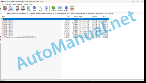
00 0290 602 0.pdf
00 0293 670 4.pdf
00 0293 676 1.pdf
00 0294 091 3.pdf
00 0302 343 1.pdf
00 0302 565 2.pdf
00 0303 815 1.pdf
00 0305 863 0.pdf
CHP-numbers for connectors CLAAS HARNESS PARTS.pdf
00 0290 602 0.pdf:
Introduction
Validity of the manual
Circuit diagrams
13c Straw and chaff spreading. Radial spreader with spreading characteristics
13c Straw and chaff spreading. Radial spreader with spreading characteristics
Key to diagram
Measuring value table
Description of function
Spreading mode switch U039
Description of function
Connector pin assignment
Interconnection list
Module outfitting
Module A51 – Radial spreader
Designations
Connector pin assignment
00 0293 670 4.pdf:
LEXION 570 – 520 Montana – Technical Systems, Hydraulic System
1 Hydraulic System – General
1.1 Hydraulic System – General
1.1.1 Oil Tank (entire hydraulic system)
1.1.2 Hydraulic Pumps
1.1.3 Hydraulic Motors
1.1.4 Valve Inserts
1.2 Overall Hydraulic System Circuit Diagram
1.2.1 Overall hydraulic system circuit diagram
LEXION Montana 570 – 520 up to serial no. 582 00051, 581 00026, 580 00028
1.2.2 Overall hydraulic system circuit diagram
LEXION Montana 570 – 520 from serial no. 581 00027 to 581 00037
1.2.3 Overall hydraulic system circuit diagram
LEXION Montana 570 – 520 – serial no. 582 00052 – 582 00153, 581 00038 – 581 00162, 580 00029 – 580 00071
1.2.4 Overall hydraulic system circuit diagram
LEXION Montana 570 – 520 – from serial no. 582 00154, 581 00163, 580 00072
Key to diagram:
1.3 Multi-coupling
2 Steering Hydraulics
2.1 Steering Hydraulics Circuit Diagrams
2.1.1 Steering Hydraulics Circuit Diagram with AUTOPILOT for concave adjustment with filling valve – LEXION 600 / 580 / 570
2.1.2 Steering Hydraulics Circuit Diagram with AUTOPILOT for concave adjustment without filling valve – LEXION 560 – 510
2.1.3 Steering Hydraulics Circuit Diagram without AUTOPILOT
2.2 Steering
2.2.1 Function of Steering
2.2.2 Function of Steering – double-stage Orbitrol units
2.3 AUTOPILOT
2.3.1 AUTOPILOT Right/Left Function
3 Working Hydraulics
3.1 Working Hydraulics Circuit Diagram
3.1.1 Working hydraulics circuit diagram
3.1.2 Working hydraulics circuit diagram
3.1.3 Working hydraulics circuit diagram
3.2 Front attachmentraise/ lower main solenoid valve
3.2.1 Main Valve
3.3 Concave Adjustment
3.3.1 Concave Adjustment – LEXION 600 / 580 / 570 Hydro-Pneumatic Overload System with Filling Valve
3.3.2 Concave Adjustment – LEXION 560 – 510 Hydraulic Overload System without Filling Valve
3.4 Threshing Drum Speed Control
3.4.1 Threshing Drum Speed Control
3.5 Uni-spreader / Radial spreader / Swing Swathing Flap
3.5.1 Swing Radial spreader
3.5.2 Swing Swathing Flap
3.6 Swing Grain Tank Unloading Tube
3.6.1 Swing Grain Tank Unloading Tube
3.7 Rotor Speed Control
3.7.1 Rotor Speed Control
3.8 Front Attachment Quick Stop
3.8.1 Front Attachment Quick Stop
3.9 Cutterbar Spring Lock
3.9.1 Cutterbar Spring Lock
3.10 Feed Rake Conveyor / FrontAttachment Speed Controller
3.10.1 Feed Rake Conveyor / Front Attachment Speed Controller
3.11 Open / close graintank (hydraulic) Grain Tank Unloading Aid
3.11.1 Open / close grain tank (hydraulic)
3.11.2 Grain Tank Unloading Aid
3.12 AUTO-CONTOUR (CAC)
3.12.1 AUTO-CONTOUR (CAC) – Front attachment cross levelling – LEXION Montana up to serial no. 582 00051, 581 00037, 580 00028
3.12.2 AUTO-CONTOUR (CAC) – Front attachment cross levelling – LEXION Montana from serial no. 582 00052, 581 00038, 580 00029
3.13 Reverse Front Attachment
3.13.1 Reverse front attachment – LEXION Montana 570 – 520
3.14 Front attachment dampening
3.14.1 Front attachment dampening – on front attachment cylinders with a spring
3.14.2 Front attachment dampening – with front attachment cylinder without a spring (CAC II)
3.15 Half-tracks Tension
3.15.1 Half tracks tension
3.15.2 Half tracks tension
3.16 Cutting frame adjustment Montana
3.17 Cutting angle adjustment Montana
3.18 Service brake
3.18.1 Filling the brake accumulator – LEXION 600 Terra Trac, LEXION Montana
4 Low-pressure Hydraulic System
4.1 Low-pressure hydraulic system – Basic functions
4.1.1 Low-pressure hydraulic system circuit diagram LEXION 600 (Wheeled machine)
4.1.2 Low-pressure hydraulic system circuit diagram LEXION 600 Terra Trac
4.1.3 Low-pressure Hydraulic System Diagram LEXION 580 – 510
4.1.4 Pressure Relief Valve Of Low-pressure Hydraulic System
4.1.5 Low-pressure hydraulic system solenoid valves
4.1.6 Hydraulic Cylinder of Low-pressure Hydraulic System
4.1.7 3-D Cleaning System
4.1.8 Grain Tank Unloading Chain Lubrication
4.2 Low-pressure hydraulic system – Additional Montana functions
4.2.1 Low-pressure hydraulic system circuit diagram
LEXION Montana 570 – 520 – Differential lock, parking brake, gearshift for 1st and 2nd gear
4.2.2 Low-pressure hydraulic system solenoid valves – LEXION Montana 570 – 520
4.2.3 Hydraulic cylinders of low-pressure hydraulic system
4.2.4 Position of low-pressure hydraulic system components – LEXION Montana
5 Electro-hydraulic Gearshift (EHS)
5.1 Electro-hydraulic gearshift circuit diagram LEXION Montana 570 – 520
6 Straw and Chaff Spreading
6.1 Straw and Chaff Spreader
6.1.1 Straw and Chaff Spreader Circuit Diagram
6.1.2 Straw and Chaff Spreader Drive
6.2 Radial spreader
6.2.1 Radial spreader circuit diagram
6.2.2 Radial spreader working/transport position
6.2.3 Radial spreader transport position
6.2.4 Radial spreader – deflector drive
7 Radiator Cleaning
7.1 Rotary Chaff Screen
7.1.1 Rotary Chaff Screen Circuit Diagram
7.1.2 Rotary Chaff Screen Drive
8 Ground Drive Hydraulics
8.1 Hydrostatic Ground Drive – Montana
8.1.1 Hydrostatic Ground Drive Circuit Diagram – Montana
up to serial no. 582 00051, 581 00037, 580 00028
8.1.2 Hydrostatic Ground Drive Circuit Diagram – Montana
serial no. 582 00052 – 582 00153, 581 00038 – 581 00162, 580 00029 – 580 00071
8.1.3 Hydrostatic Ground Drive Circuit Diagram – Montana
from serial no. 582 00153, 581 00163, 580 00072
8.1.4 Ground drive control pressure
8.1.5 Pump Unit
8.1.6 Motor unit
8.1.7 Ground drive hydraulic motor brake restrictor (HBM) control – external brake function
up to serial no. 582 00051, 581 00037, 580 00028
8.1.8 Ground drive hydraulic motor brake restrictor control – integrated brake function
from serial no. 582 00052, 581 00038, 580 00029
8.2 4-Trac Drive (All-wheel drive)
8.2.1 MUD HOG valve unit
8.2.2 POCLAIN radial piston motor
8.2.3 4-Trac Overdrive
9 Axle Hydraulics (Montana)
9.1 Axle hydraulics circuit diagram
9.1.1 Axle hydraulics circuit diagram LEXION Montana 570 – 520 up to serial no. 582 00051, 581 00037, 580 00028
9.1.2 Axle hydraulics circuit diagram LEXION Montana 570 – 520 serial no. 582 00052 – 582 0153, 581 00038 – 581 00162, 580 00028 – 580 00071
9.1.3 Axle hydraulics circuit diagram LEXION Montana 570 – 520 from serial no. 582 0154, 581 00163, 580 00072
9.2 Axle control system (Montana)
9.2.1 Axle control system – Master valve / pressure relief valve up to serial no. 582 00051, 581 00037, 580 00028
9.2.2 Axle control system – Master valve / pressure relief valve from serial no. 582 00052, 581 00038, 580 00029
9.2.3 Axle control system – raise / lower axle, oil quantity increase up to serial no. 582 00051, 581 00037, 580 00028
9.2.4 Axle control system – raise / lower axle, oil quantity increase from serial no. 582 00052, 581 00038, 580 00029
9.3 Shifting aid (Montana)
9.4 Position of components / Axle control system
10 Brake system
10.1 Brake system LEXION Montana 570 – 520
11 Standard Cutterbar
11.1 Standard Cutterbar Circuit Diagram
11.2 Vertical Reel Adjustment (Standard Cutterbar)
11.3 Horizontal Reel Adjustment (Standard Cutterbar)
11.4 Reel Rpm Adjustment (Standard Cutterbar)
11.5 Rape Knife Drive (Standard Cutterbar)
12 Vario Cutterbar
12.1 Vario Cutterbar Circuit Diagram
12.2 Vertical Reel Adjustment (Vario Cutterbar)
12.3 Horizontal Reel Adjustment (Vario Cutterbar)
12.4 Reel Rpm Adjustment (Vario Cutterbar)
12.5 Cutting Table Adjustment (Vario Cutterbar)
12.6 Rape Knife Drive (Vario Cutterbar)
13 Folding Cutterbar
13.1 Folding Cutterbar Circuit Diagram
13.2 Vertical Reel Adjustment (Folding Cutterbar)
13.3 Horizontal Reel Adjustment (Folding Cutterbar)
13.4 Reel Rpm Adjustment (Folding Cutterbar)
13.5 Folding the cutterbar
14 Conspeed Maize Picker
14.1 Conspeed Maize Picker Circuit Diagram / 6-row (type 908)
14.2 Conspeed Maize Picker Circuit Diagram / 8-row (type 907)
14.3 Folding the Snapping Units / Adjusting the Snapping Plates – Conspeed Maize Picker
14.4 Reel Rpm Adjustment (Conspeed Maize Picker)
15 MaxFlex cutterbar
15.1 MaxFlex Cutterbar Circuit Diagram
15.2 Vertical Reel Adjustment (MaxFlex Cutterbar)
15.3 Horizontal Reel Adjustment (MaxFlex Cutterbar)
15.4 Reel Rpm Adjustment (MaxFlex Cutterbar)
15.5 Cutterbar lock (MaxFlex cutterbar)
Position of components
Component grid
0293 670.4
00 0293 676 1.pdf:
Technical Systems – Electric System LEXION 570 – 520 MONTANA, up to serial number: 582 00092, 581 00082, 580 00049
Layout of electric circuit diagrams
Central terminal compartment
Central terminal compartment (LEXION 600-510)
Central terminal compartment Montana 570-520 – with external MONTANA control unit
Central terminal compartment Montana 570-520 – with integrated MONTANA control unit
Pin assignment in modules
Module A6 – Automatic air conditioner
Module A7 – Cab fan speed controller
Module A8 – AUTOCONTOUR (CAC)
Module A9 – AUTOPILOT (ATP)
Module A10 – Fieldwork computer (BIF/CAB)
Module A12 – Speed monitor (DZW)
Module A13 – Performance monitor (DKG)
Module A15 – Electronic engine control module CATERPILLAR (CAT C13, C12, C10, C9, 3126B)
Module A15 – Electronic engine control module CATERPILLAR (CAT C 6.6)
Module A15 – Electronic engine control module DAIMLER-CHRYSLER (DC)
Module A17 – Engine adaptation module ADM DAIMLER-CHRYSLER (DC)
Module A16 – Reel controller
Module A21 – Yield meter
Module A25 – Sieve adjustment
Module A27 – VARIO
Module A28 – Uni-spreader (VGS)
Module A30 – Terminal
Module A33 – Sidefinder
Module A34 – Grain tank
Module A35 – Montana 570-520 control unit – with external MONTANA control unit
Module A36 – Montana 570-520 gearshift module – with external MONTANA control unit
Module A37 – Electro-hydraulic gearshift (EHS) – 3-speed manual gearbox
Module A37 – Electro-hydraulic gearshift (EHS) – 2-speed manual gearbox
Module A38 – Rotor (RIO)
Module A42 – MONTANA GEN II module – with integrated MONTANA control unit
Module A45 – Ground drive hydraulic motor brake restrictor (HBM)
Module A46 – Deflector adjustment (RIO)
Module A49 – Ground drive (EFA)
Module A51 – Radial spreader
Module A65 – GPS pilot terminal
Module A66 – GPS pilot module (GPB)
Circuit diagrams 01a – 50a
01a Main power supply, diesel engine electric starting motor
01s Main power supply, diesel engine electric starting motor – Montana 570-520
02a Starting the diesel engine, diesel engine electric starting motor – CAT C12, C10, C9, 3126B
02b Starting the diesel engine, diesel engine electric starting motor – DC 502 LA
02c Starting the diesel engine, diesel engine electric starting motor – DC 502 LA, with electro-hydraulic ground drive (EFA)
02d Starting the diesel engine, diesel engine electric starting motor – CAT C6.6
02e Starting the diesel engine, diesel engine electric starting motor – C13 ACERT, C9 ACERT (TIER III)
02s Starting the diesel engine, diesel engine speed adjustment – CAT C12, C10, C9, 3126B, Montana 570-520 – with external MONTANA control unit
02t Starting the diesel engine, diesel engine speed adjustment – CAT C12, C10, C9, 3126B, Montana 570-520 – with integrated MONTANA control unit
03a Diesel engine cut-off system
04a Road travel activation, master valve
04b Road travel activation, master valve – with electro-hydraulic ground drive (EFA)
04s Road travel activation, working hydraulics master valve, Montana 570-520 – with external MONTANA control unit
04t Road travel activation, working hydraulics master valve, Montana 570-520 – with integrated MONTANA control unit
05a Terminal, keyboard, rotary switch, printer
05b Terminal, keyboard, rotary switch, printer – with electro-hydraulic ground drive (EFA)
06a CAN bus, module power supply, for diesel engine CATERPILLAR – C12, C10, C9, 3126B
06b CAN bus, module power supply, for diesel engine Daimler – Chrysler DC 502 LA – without electro-hydraulic ground drive (EFA)
06c CAN bus, module power supply, for diesel engine CATERPILLAR – C13 ACERT (TIER III) – with electro-hydraulic ground drive (EFA)
06d CAN bus, module power supply, for diesel engine Daimler – Chrysler DC 502 LA, – with electro-hydraulic ground drive (EFA)
06e CAN bus, module power supply, for diesel engine CATERPILLAR – C6.6
06f CAN bus, module power supply, for diesel engine CATERPILLAR – C9 ACERT (TIER III)
06s CAN bus, module power supply, Montana 570-520 – with external MONTANA control unit
06t CAN bus, module power supply, Montana 570-520 – with integrated MONTANA control unit
07a Threshing mechanism circuit
08a Concave adjustment / Threshing drum variable-speed drive
09a Rotor flap adjustment / Rotor variable-speed drive
10a Fan variable-speed drive
11a Sieve adjustment
12a Deflector adjustment
13a Straw and chaff spreader, uni-spreader – LEXION 580
13b Straw and chaff spreader, radial spreader
14a Swinging the grain tank unloading tube
15a Grain tank unloading / Grain tank unloading aid
16a Rape cutting knife circuit
17a Front attachment drive, reverser drive, front attachment quick stop
17b Front attachment drive, reverser drive, front attachment quick stop – with electro-hydraulic ground drive (EFA)
17s Front attachment drive, reverser drive, front attachment quick stop, Montana 570-520 – with external MONTANA control unit
18a Front attachment variable-speed drive
19a Straw chopper
19b Straw chopper, radial spreader without chaff spreader
19c Straw chopper, radial spreader with chaff spreader
20a Front attachment raise/lower, cross levelling
20b Front attachment raise/lower, cross levelling – with electro-hydraulic ground drive (EFA)
20s Raise/lower front attachment, cross levelling – Montana 570-520
21a Reel adjustment – Standard cutterbar, MaxFlex soybean header
21b Reel adjustment – VARIO cutterbar
21c Reel adjustment – Folding cutterbar
21d Folding the maize picker, snapping plate adjustment, down maize augers
21e Rake-up – Drive, rake-up crop guard adjustment
22a Reel variable-speed drive
23a Cutting table adjustment (Vario), folding the cutterbar
23b MaxFlex cutting table adjustment
24a AUTOCONTOUR (CAC)
25a Speed monitor
26a Machine monitor
26b Machine monitor – with electro-hydraulic ground drive (EFA)
26s Machine monitor, Montana 570-520 – with external MONTANA control unit
26t Machine monitor, Montana 570-520 – with integrated MONTANA control unit
27a Yield meter / Grainmeter
28a AUTOPILOT – Laser system
28b AUTOPILOT – Feeler system
28c AUTOPILOT – GPS-controlled steering
29a Performance monitor
30a Open / close grain tank (electric), grain tank full signal, warning beacon
30b Open / close grain tank (hydraulic), grain tank full signal, warning beacon
31a Front attachment dampening
32a All-wheel drive, fuel tank
32b All-wheel drive – overdrive, fuel tank
32c All-wheel drive, fuel tank – with electro-hydraulic ground drive (EFA)
32d All-wheel drive – overdrive, fuel tank – with electro-hydraulic ground drive (EFA)
33a Cutterbar spring lock
36a Indicator system (Europe)
36b Indicator system (USA)
37a Windscreen wiper, windscreen washer
38a Compressor-type air conditioner
38b Automatic air conditioner
39a Cab comfort equipment – operator’s seat
40a Additional sockets, fuse tester
41s Axle control system, front attachment control system, Montana 570-520 – with integrated MONTANA control unit
41t Axle control system and front attachment control system, Montana 570-520 – with integrated Montana control unit
42a Ground drive and brake control
42b Ground drive and brake control – with electro-hydraulic ground drive (EFA) LEXION 600 TerraTrac
42s Ground drive and brake control, Montana 570-520 – with external MONTANA control unit
42t Ground drive and brake control, Montana 570-520 – with integrated MONTANA control unit
43a Electro-hydraulic ground drive (EFA)
44a Electro-hydraulic gearshift – 3-speed manual gearbox
44b Electro-hydraulic gearshift – 2-speed manual gearbox
45a Main lighting circuit, taillight, position light
46a Dipped headlights, full beam, dipped headlights changeover switch
47a Work lights I
48a Work lights II
49a Sieve, grain tank and returns lighting, reversing horn, brake light
49b Sieve, grain tank and returns lighting, reversing horn, brake light – with electro-hydraulic ground drive (EFA)
50a Instrument lighting, broadcast receiver, mirror adjustment
Component grid
0293 676.1
00 0294 091 3.pdf:
LEXION 570 – 520 Montana From serial number: 582 00093, 581 00083, 580 00050 – Technical Systems, Electric System
Central terminal compartment Montana 570-520 – with integrated MONTANA control unit
Interconnections within central terminal compartment
Connecting cable (module PCB – base PCB)
Pin assignment in modules
Module A6 – Automatic air conditioner
Module A7 – Cab fan speed controller
Module A8 – AUTOCONTOUR (CAC)
Module A9 – AUTOPILOT (ATP)
Module A10 – Fieldwork computer (BIF/CAB)
Module A12 – Speed monitor (DZW)
Module A13 – Performance monitor (DKG)
Module A15 – Electronic engine control module CATERPILLAR (CAT C13, C12, C10, C9, 3126B)
Module A15 – Electronic engine control module CATERPILLAR (CAT C 6.6)
Module A15 – Electronic engine control module DAIMLER-CHRYSLER (DC)
Module A17 – Engine adaptation module ADM DAIMLER-CHRYSLER (DC)
Module A16 – Reel controller
Module A21 – Yield meter
Module A25 – Sieve adjustment
Module A27 – VARIO
Module A30 ��� Terminal Cebis
Module A33 ��� Sidefinder
Module A34 ��� Grain tank
Module A37 ��� Electro-hydraulic gearshift (EHS) ��� 3-speed manual gearbox
Module A37 ��� Electro-hydraulic gearshift (EHS) ��� 2-speed manual gearbox
Module A38 ��� Rotor adjustment (RIO)
Module A51 ��� Radial spreader
Module A65 ��A� 4-Trac enable module
Circuit diagrams 01a – 50a
01m Main power supply, diesel engine electric starting motor – Montana 570-520
02a Starting the diesel engine, diesel engine electric starting motor – C13 ACERT, C9 ACERT (TIER III)
02b Starting the diesel engine, diesel engine electric starting motor – CAT C12, 3126B
02c Starting the diesel engine, diesel engine electric starting motor – CAT C6.6
03a Diesel engine cut-off system
04m Road travel activation, master valve – Montana 570-520
05m Terminal, keyboard, rotary switch, printer – Montana 570-520
06m CAN bus, module power supply – Montana 570-520
07a Threshing mechanism circuit
08a Concave adjustment / Threshing drum variable-speed drive
09a Rotor flap adjustment / Rotor variable-speed drive
10a Fan variable-speed drive
11a Sieve adjustment
12haff spreader, radial spreader
14a Swinging the grain tank unloading tube
15a Grain tank unloading / Grain tank unloading aid
16a Rape cutting knife circuit
17a Front attachment drive, reverser drive, front attachment quick stop
18a Front attachment variable-speed drive
19a Straw chopper – Standard chopper for LEXION 570-510
19b Straw chopper – Radial spreader for LEXION 600-570
20a Front attachment raise/lower, cross levelling
21a Reel adjustment – Standard cutterbar, folding cutterbar, MaxFlex soybean header
21b Reel adjustment – VARIO cutterbar
21c Maize picker Conspeed – Folding the maize picker, snapping plate adjustment, down maize augers
21d Rake-up – Drive, rake-up crop guard adjustment
22a Reel variable-speed drive
23a Cutting table adjustment (Vario), folding the cutterbar
24a AUTOCONTOUR (CAC)
25a Speed monitor
26m Machine monitor – Montana 570-520
27a Yield meter / Grainmeter
28a AUTOPILOT – Laser system
28b AUTOPILOT – Feeler system
28c AUTOPILOT – GPS-controlled steering
29a Performance monitor
30a Open / close grain tank (electric), grain tank full signal, warning beacon
31a Front attachment dampening
32a All-wheel drive – overdrive, fuel tank (not with electro-hydraulic ground drive)
33a Cutterbar spring lock (only when front attachment cylinder is equipped with a spring)
36a Indicator system (Europe)
37a Windscreen wiper, windscreen washer
38a Compressor-type air conditioner
38b Automatic air conditioner
39a Cab comfort equipment – operator’s seat
40a Additional sockets, fuse tester
41m Axle control system and front attachment control system – Montana 570-520
42m Ground drive and brake control – Montana 570-520
44m Electro-hydraulic gearshift (EHS) – 2-speed manual gearbox – Montana 570-520
45a Main lighting circuit, taillight, position light
46a Dipped headlights, full beam, dipped headlights changeover switch
47a Work lights I
48a Work lights II
49a Sieve, grain tank and returns lighting, reversing horn, brake light (not with electro-hydraulic ground drive)
49b Sieve, grain tank and returns lighting, reversing horn, brake light – with electro-hydraulic ground drive (EFA)
50a Instrument lighting, broadcast receiver, mirror adjustment
Component grid
00 0294 091.3
00 0302 343 1.pdf:
PROFI CAM 3
Table of contents
General information
Marking of warnings and hazard prevention notes
First-aid measures
CCN explanation
CCN (CLAAS Component Number)
Electric system standard
Hydraulic system standard
CCN (CLAAS Component Number)
10 Electrical / Electronic equipment
1030 Board computer / Indicators
Camera system
Description of function
1097 Testing / Measuring / Adjusting
Testing / measuring / adjusting the PROFI CAM
Checking the fuse in the video channel select box (C102)
Testing the video camera connector (C055)
1098 Fault / remedy
Fault / remedy PROFI CAM
The video monitor (C101) shows no image or cannot be switched on (indicator light fails to light up)
Video monitor (C102) displays a blue image either permanently or temporarily
The video monitor image is blurred
Replacing the fuse in the video channel select box (C102)
Connection and connecting cable with video camera (C055)
00 0302 565 2.pdf:
Sensor system
Table of contents
CCN explanation
CCN (CLAAS Component Number)
Electric system standard
Hydraulic system standard
CCN (CLAAS Component Number)
Introduction
Safety rules
Safety and hazard information
10 Electrical / Electronic equipment
1097 Testing / Measuring / Adjusting
Test report of the angle sensor (0011780.x)
Application of test report
Required tools
Test report of the angle sensor (0011780.x)
Testing / Measuring / Adjusting of angle sensor (0011780.x)
1. Reason for test
2. Mechanical test of angle sensor
3. Electric test with CDS
4. Electric test with multimeter
5. Mechanical test of connecting cable
Completing the machine
Test report of position and speed sensors
Application of test report
Required tools
Sensor variants
Part numbers of speed sensors
Part number of position sensor
Test report of position and speed sensors
Testing / measuring / adjusting of position and speed sensors
1. Reason for test
2. Mechanical test
3. Electric test with CDS
4a. Installation dimensions
Check of installation dimension
Installation dimensions of gearbox speed sensor (0011 799.x) and cam speed sensor (0011 810.x)
Installation dimension of position sensor (0011 815.x)
4b. Installation position
Centring of sensor
Metal-free zone
5. Electric test with multimeter
Voltage measurement
Direction of rotation and speed sensor (0011 605.x)
Measured values table
6. Mechanical test of connecting cable
Completing the machine
Test report of the urea sensor (00 0773 207 x)
Application of test report
Required tools
Parts number of the urea sensor
Test report of the urea sensor
Testing / measuring / adjusting urea sensor
1. Reason for test
2. Mechanical test
3. Mechanical test of connecting cable
4. Electric test with multimeter
5. Component test with the CDS
00 0305 863 0.pdf:
LEXIONJAGUARXERION
Table of contents
Introduction
Notes on the manual
Validity of manual
Information about this Technical Systems Manual
Identifying warnings
Hazard signs
Signal word
0125 Injection / Fuel system
Injection / fuel system
Required tools and aids
Line valves for connecting to the engine
Valves and adapters for tank feed and return lines
Measuring setup (possible variant)
Test procedure
A – Leakage test of tank return line and possibly of tank suction line
B – Leakage test of feed lines (possibly including fuel sediment filter)
C – Test of non-return valve in the line (if provided)
D – Leakage test of return lines (possibly including the fuel cooler)
E – Leakage test of fuel sediment filter
F – Leakage test of engine
Steps 1 – 3
Fuel diagrams
Remarks about the circuit diagrams
LEXION fuel diagram
Key to diagram
JAGUAR with Mercedes-Benz OM47x LA
Key to diagram
JAGUAR with MAN D2862 (V12)
Key to diagram
CHP-numbers for connectors CLAAS HARNESS PARTS.pdf:
CLAAS HARNESS PARTS
Table of contents
10 Electrical / Electronic equipment
1081 Overview of connectors
CLAAS HARNESS PARTS (CHP)
John Deere Repair Technical Manual PDF
John Deere Repair Technical Manual PDF
John Deere Repair Technical Manual PDF
John Deere Repair Technical Manual PDF
John Deere Repair Technical Manual PDF
John Deere Repair Technical Manual PDF
John Deere 18-Speed PST Repair Manual Component Technical Manual CTM168 10DEC07
John Deere Repair Technical Manual PDF
John Deere Diesel Engines PowerTech 4.5L and 6.8L – Motor Base Technical Manual 07MAY08 Portuguese
John Deere Repair Technical Manual PDF
John Deere Repair Technical Manual PDF

