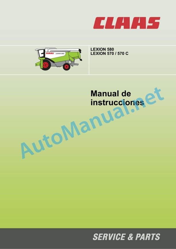
Claas Lexion 570 580 R (585) Combines Operator Manual ES
$50.00
- Model: Lexion 570 580 R (585) Combines
- Type Of Manual: Operator Manual
- Language: ES
- Format: PDF(s)
- Size: 125 MB
File List:
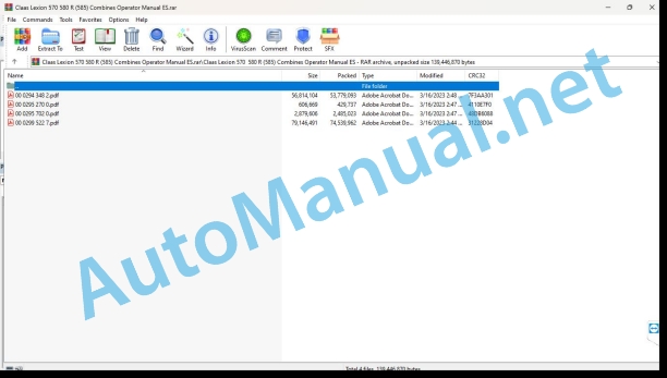
00 0294 348 2.pdf
00 0295 270 0.pdf
00 0295 702 0.pdf
00 0299 522 7.pdf
00 0294 348 2.pdf:
1. Introduction
1.1 General instructions
1.1.1 Using the instructions
1.1.2 Validity of the manual
2 General instructions
2.1 Road traffic
2.2 Especially important
2.3 Identification plate / Serial number
2.3.1 Identification plate
2.3.2 Machine serial number
2.3.3 Engine serial number
2.3.4 Identification plate – straw chopper
2.3.5 Cabin number
2.4 Assembled parts/machine casing
2.4.1 Access to the workplace and maintenance stations
3 Security measures
3.1 Safety instructions
3.1.1 General instructions
3.1.2 Warning and danger signs
3.1.3 Proper use of the machine
3.1.4 Predictably foolish misuse
3.1.5 General prescriptions for safety and accident prevention
3.1.6 Transportation of people, trainer, operational personnel
3.1.7 Driving the machine
3.1.8 Getting off the combine
3.1.9 Heads (cutting mechanisms and others) and other construction parts
3.1.10 Air conditioning installation
3.1.11 Maintenance
3.1.12 Fundamental rule
3.1.13 Pressure accumulator
3.1.14 Decommissioning and waste disposal
3.1.15 Security support
3.1.16 Fire extinguisher
3.1.17 Battery separator switch
3.1.18 Shims
3.1.19 Raise the machine on blocks
3.1.20 Load and tie down the machine
3.1.21 Hydraulic installation
3.1.22 Risk of accident due to hydraulic fluid
3.1.23 Pressure accumulator
3.1.24 Unload the concave adjustment pressure retainer
3.2 Safety stickers with warning symbols
3.2.1 General information on warning symbols
3.2.2 Warning symbols
4 Technical data
4.1 LEXION 580R – type 585
4.1.1 Driver’s cabin/platform
4.1.2 Cutting mechanism
4.1.3 Threshing organs
4.1.4 Separation
4.1.5 Cleaning (JET STREAM cleaning system)
4.1.6 Grain collection
4.1.7 Engine
4.1.8 Undercarriage
4.1.9 Tires and air pressure
4.1.10 Wheel stud tightening values
4.1.11 Track width
4.1.12 Transport position / working position
4.1.13 Weights
4.1.14 Safety devices
5 Before start-up
5.1 General instructions
5.1.1 Checklist for first start-up
5.2 Cabin
5.2.1 Cabin with automatic air conditioning system
5.2.2 Automatic air conditioning system
5.2.3 Commissioning the automatic air conditioning system
5.2.4 Regulate the cabin temperature
5.2.5 Manual regulation of the vaporizer fan revolutions
5.2.6 Start ECON operation
5.2.7 Turn off ECON operation
5.2.8 REHEAT operation (defogging the cabin windows)
5.2.9 Show outside temperature
5.2.10 Change the temperature display to ˚Fahrnheit
5.2.11 Foot area heating
5.2.12 Fault indication – F0 temperature meter fault (space, blue)
5.2.13 Fault indication – F1 temperature meter fault (air outlet, yellow)
5.2.14 Fault indication – F2 temperature meter fault (outside, red)
5.2.15 Incident, possible cues and solutions – air conditioning equipment
5.2.16 Refrigerator
5.2.17 Ice bucket (optional equipment)
5.2.18 Window washer equipment
5.2.19 Harvest control
5.2.20 Open or close the cabin roof
5.2.21 Cabin emergency exit
5.2.22 Driver platform box
5.2.23 Dashboard
5.2.24 Screen (preview screen)
5.2.25 Screen (harvest screen)
5.2.26 Area C keys / rotary switch D
5.2.27 Ignition contact
5.2.28 Multifunctional switch
5.2.29 Central reporter
5.2.30 Multifunctional handle
5.2.31 Reel height limitation
5.2.32 Change the position of the steering bar
5.2.33 Adjust the height of the steering wheel
5.2.34 Central electrical system
5.2.35 Index of the central electrical system (up to machine no. …)
5.2.36 Fuses (up to machine no. …)
5.2.37 Relay
5.2.38 Driver’s seat
5.2.39 Driver’s pneumatic seat
5.2.40 Driver’s seat, mechanical version
5.3 Lighting and sockets
5.3.1 Advance lighting, work lights, mirrors
5.3.2 Sidefinder (optional equipment)
5.3.3 Wayfinder lighting
5.3.4 12 V sockets
5.3.5 CDS 5000 diagnostic connection plug
5.4 Access ladder
5.4.1 Mount the extension and handrail at the front (if applicable)
5.4.2 Rotate the front ladder
5.4.3 Ladder protection
5.4.4 Rear staircase
5.5 Side covers
5.5.1 Open and close the side covers and tailgate
5.5.2 Open the tailgate
5.5.3 Adjust the height of the side cover handle
5.5.4 Adjust the closure of the side cover
5.5.5 Tool drawer
5.6 Mudguards / side panels
5.6.1 Mount the fenders
5.7 Guiding axes (JET STREAM cleaning system)
5.7.1 Steering axle summary
5.7.2 Drive steering axle 000 694 820 1
5.7.3 Steering axle 000 768 980 1
5.7.4 Transform the drive steering axle 000 694 960 2 / 000 694 820 1 from the transport position to the working position
5.7.5 Adjust the track width of the drive steering axle 000 694 960 2/000 694 820 1
5.7.6 Changing the steering axle 000 768 980 1 from the transport position to the working position
5.7.7 Steering axle 000 768 980 1 – adjust track width
5.8 Hydraulic cylinders of the cutting mechanism
5.8.1 Hydraulic cylinder of springless cutting mechanism
5.8.2 Number of cutting mechanism cylinders
5.9 Pressure retainer
5.9.1 Filling the pressure accumulator for CLAAS AUTO CONTOUR II
5.9.2 Special tool for filling the pressure retainer for CLAAS AUTO CONTOUR II
5.10 Twin wheels
5.10.1 Install the twin wheels
5.11 Grain deposit
5.11.1 Close the grain tank outlet holes
5.12 Driving the combine with mechanical gear drive
5.12.1 Driving the machine
5.12.2 Variants of the feed lever
5.12.3 Rotary switch for engine speed
5.12.4 Average engine idle speed
5.12.5 Start the engine
5.12.6 Forward feed/reverse feed
5.12.7 Gear change
5.12.8 Adjusting the reaction smoothness of the feed lever
5.12.9 Adjusting the reaction smoothness of the feed lever
5.12.10 Stop
5.12.11 Machine driving characteristics
5.12.12 Trailer driving characteristics for the cutting mechanism
5.12.13 Steer the machine
5.12.14 Engage/disengage the brake pedals from the foot brake
5.12.15 Parking brake
5.12.16 Stop the engine
5.12.17 CLAAS 4-wheel drive system disengage/engage
5.12.18 Towing the machine
5.12.19 Tow ahead
5.12.20 Towing from behind
5.12.21 Gear change process EHS emergency operation via gear key (from machine no. …)
5.12.22 Emergency activation sticker – Electro-hydraulic gear shift (EHS)
5.12.23 Mechanically placing the neutral position on the gearbox
5.12.24 Return to basic position (gear can be changed again electro-hydraulically in the gearbox)
5.12.25 Putting the gearbox in neutral position hydraulically
5.12.26 Shift into 2nd gear hydraulically
5.13 CLAAS autopilot (corn milking head)
5.13.1 Put CLAAS Autopilot into operation
5.14 CLAAS autopilot (cereal cutting mechanism)
5.14.1 Adjusting the straight line running of the combine
5.14.2 Orient the laser sensor in relation to the field
5.14.3 Rough adjustment
5.14.4 Exact adjustment
5.14.5 Laser sensor (cereal edge has been lost from sight)
5.14.6 Adjusting the right laser sensor (additional equipment)
5.14.7 Put CLAAS Autopilot into operation
5.14.8 Use in rapeseed with left side blade
6 Assembling and disassembling the cutting mechanism
6.1 Assemble the cutting mechanism
6.1.1 Tip the cutting mechanism out of the transport position
6.1.2 Adjust the hydraulic cylinders for transverse adjustment of the cutting mechanism (from machine no. …)
6.1.3 Attach the front implement
6.1.4 Locking corn cutterbars and milking heads (cutters without Auto-Contour)
6.1.5 Connect the cardan shaft
6.1.6 Place the support legs
6.2 Dismantle the cutting mechanism
6.2.1 Connect the universal clutch
6.2.2 Disconnect the cardan shaft
6.2.3 Open the cutting mechanism lock
6.2.4 Place the cutting mechanism on the ground
6.2.5 Placing the cutting deck on the cutting deck trailer
7 CEBIS Management (Version 8.23)
7.1 CLAAS CEBIS on-board information system
7.2 CEBIS monitor and rotary switch
7.2.1 Area C keys
7.2.2 Rotary switch D
7.2.3 Box of flags
7.2.4 Multifunctional handle
7.2.5 Screen zones E (harvest screen)
7.3 Rotary switch D
7.4 Before first start-up
7.5 Progress screen
7.6 Harvest Screen
7.7 Montana Regulation
7.7.1 Axis adjustment mode
7.7.2 Cutting angle regulator
7.7.3 Transverse compensation regulator
7.7.4 Montana axis end stops
7.7.5 Cutting angle end stops
7.7.6 Transverse compensation end stops
7.7.7 Indication duration
7.8 CLAAS CRUISE PILOT
7.8.1 Maximum speed
7.8.2 Harvest step zero point
7.9 Yield mapping
7.10 Flagging
7.11 GPS
7.11.1 ON/OFF Cartography
7.11.2 Mapping indicator
7.11.3 Load GPS data
7.12 Reel Presets
7.12.1 Horizontal position of the reel
7.12.2 Reel speed
7.12.3 Reel height
7.13 Front implement pre-adjustments
7.13.1 Distance of the starting plates
7.13.2 Length of the cutting mechanism table
7.13.3 CAC Adjustment
7.13.4 Adjustment CAC LEXION Montana
7.14 Switching dividing widths
7.15 Performance Meter
7.15.1 Components
7.15.2 Basic adjustment and calibration
7.15.3 Preparation for performance measurement
7.15.4 Humidity measurement ON/OFF, humidity correction, storage humidity
7.15.5 Fast path to realistic measurement data
7.16 Performance measurement
7.16.1 Calibration factor
7.16.2 Performance zero point measurement
7.16.3 Counterbalanced
7.16.4 Checked weight
7.16.5 Humidity correction
7.16.6 Humidity measurement ON / OFF
7.16.7 Zero angle
7.16.8 Storage humidity
7.16.9 Dry crop material
7.17 Adjustment depending on the fruit
7.17.1 List of shellable fruits
7.17.2 Clean by blowing
7.18 Registration
7.18.1 Planned assignments
7.18.2 Start / Stop
7.18.3 Shipped orders
7.18.4 Daily counter
7.18.5 Total counter
7.18.6 Fruit counter
7.18.7 Copy the chip card
7.19 Adjust
7.19.1 Cutting mechanism
7.19.2 Speed
7.19.3 Tachometer
7.19.4 Separation
7.19.5 CEBIS
7.19.6 Maintenance
7.19.7 Instructions for use
7.19.8 Security code
7.20 Engine load
7.20.1 Engine diagnosis
7.21 Alarms
7.22 Indications
7.23 Incident / solution – performance measurement device
7.24 Guide values for pulses/100 m
8 Operation – base machine
8.1 HP Power Channel
8.1.1 Adjust the height of the feed chains
8.1.2 Adjust the cutting angle of the HP feed channel to the initial position (optional equipment) (up to machine no. …)
8.1.3 Adjust the cutting angle of the HP feed channel to the initial position (optional equipment) (from machine no. … to machine no. …)
8.1.4 Setting the cutting angle of the HP feed channel to the initial position (optional equipment) (from machine no. …)
8.1.5 Device for reversing the direction of travel of f implement
8.1.6 Cutting height indicator
8.1.7 Adjust the lowering speed of the front implement
8.1.8 Connect the front implement
8.1.9 Disconnect the head at the control desk
8.1.10 Disconnect the head on the multifunction controller
8.1.11 Modify the speed of the drive chains with the stepped drive of the 2nd level head (optional equipment)
8.2 Standard feed channel
8.2.1 Adjust the height of the feed chains
8.2.2 Safety device for the feed chain
8.2.3 Device for reversing the direction of travel of the front implement
8.2.4 Cutting height indicator
8.2.5 Adjust the lowering speed of the front implement
8.2.6 Connect the front implement
8.2.7 Disconnect the head at the control desk
8.2.8 Disconnecting the head on the multifunction controller
8.2.9 Modifying the speed of the drive chains with the stepped drive of the 2nd level head (optional equipment)
8.3 Threshing organs
8.3.1 Stone collecting device (large stone collecting device)
8.3.2 Connect and disconnect the threshing devices
8.3.3 Disconnect the threshing devices
8.3.4 Sheller cylinder
8.3.5 Clean the threshing components
8.3.6 Concave adjustment
8.3.7 Centrally readjust the concave
8.3.8 Readjust the concave on the left
8.3.9 Adjust the oil pressure on the concave adjustment pressure retainer
8.3.10 Basic concave adjustment
8.3.11 Denominations and measurements cereal concave / corn concave
8.3.12 Adjust the concave position sensor
8.3.13 Speed of shelling cylinder revolutions
8.3.14 Sheller cylinder drives
8.3.15 Two-step drive
8.3.16 Dismantle and assemble the pre-concave segments (large stone collecting device)
8.3.17 Threshing segment
8.3.18 Dismantling the threshing segment (large stone collection device)
8.3.19 Assemble the threshing segment (large stone collection device)
8.3.20 Sheller plates
8.3.21 Unclog the shelling cylinder
8.4 Universal rotor
8.4.1 Axial rotors
8.4.2 Axiator vaor (optional equipment)
8.4.3 Step drive of axial rotors
8.4.4 Universal rotors, speed diagram
8.4.5 Close the separation concaves
8.4.6 Replace the separation concaves with blind concaves (optional equipment)
8.4.7 Close the separation concaves with the closing covers electrically (optional equipment)
8.4.8 Dismantle and install blind concaves / separation concaves
8.4.9 Remove blind concaves / separation concaves
8.4.10 Assemble the blind concaves / separation concaves
8.4.11 Straw jamming alarm signal in the axial rotors
8.4.12 Grain passage control device for the rotors
8.4.13 Rotor sensors
8.5 Cleaning (JET STREAM cleaning system)
8.5.1 Cleaning
8.5.2 Preparation Fund
8.5.3 Blind screens
8.5.4 Electrical regulation of the sieves
8.5.5 Dismantle the sieves
8.5.6 Assemble the screens
8.5.7 Tightening torque of the axial screws of the upper and lower screens
8.5.8 Screens – basic regulation
8.5.9 Harvesting without the lower sieves
8.5.10 Cover the return (additional corn equipment)
8.5.11 Cleaning fan
8.5.12 Adjust fan speed regulation
8.5.13 Install the fan speed regulation for grass harvesting
8.5.14 Ventilated step
8.5.15 3-D Cleaning
8.5.16 Return
8.5.17 Control return
8.5.18 Grain passage control device for the upper sieve
8.5.19 Sieve box sensor
8.6 Grain collection
8.6.1 Augers and auger trays
8.6.2 Elevators
8.6.3 Grain storage
8.6.4 Grain tank top frame
8.6.5 Unload the grain tank
8.6.6 Emergency unloading of the grain tank hatch
8.6.7 Grain tank unloading aid (additional equipment)
8.6.8 Grain tank discharge pipe
8.6.9 Unfold and fold the grain tank discharge tube
8.6.10 Transport position of grain tank discharge pipe
8.6.11 Discharge tube cleaning hatches
8.6.12 Safety screw for grain tank discharge
8.6.13 Connecting and disconnecting the grain tank discharge
8.6.14 Entrance to the grain tank
8.6.15 Automatic chain lubrication – grain tank discharge (additional equipment)
8.6.16 Full grain tank indicator
8.7 Straw chopper
8.7.1 Straw chopper
8.7.2 Check before starting the straw chopper
8.7.3 Handling the straw chopper
8.7.4 Straw chopper with spreader
8.7.5 Put the straw chopper to work (place the spreader in chopping position)
8.7.6 Put the straw chopper in rest position (place the spreader in row position)
8.7.7 Adjusting the straw guide plate
8.7.8 Place the straw guide plate in the chopping position
8.7.9 Place the straw guide plate in the swathing position
8.7.10 Adjust the chopping length
8.7.11 Adjust the chopper spreading width
8.7.12 Reduce the speed of the chopper (from machine no. …)
8.7.13 Reduce the speed of the chopper (up to machine no. …)
8.8 Chaff spreader
8.8.1 Chaff spreader
8.8.2 Setting the spreading width of the chaff spreader
8.8.3 Fold down the chaff spreader
8.8.4 Folding up the chaff spreader (working position)
8.9 Straw spreader
8.9.1 Straw spreader
8.9.2 Adjust spreading width
8.9.3 Install the distribution fins
8.10 LEXION 580R sieve and threshing panels (JET STREAM cleaning system)
8.10.1 LEXION 580R screen panel (JET STREAM cleaning system)
8.10.2 LEXION 580R threshing table (JET STREAM cleaning system)
8.11 Shelling
8.11.1 Sheller plates
8.11.2 Threshing segment
8.11.3 Rotor flaps
8.12 Incident, cause and solution – Base machine
8.12.1 Front implement
8.12.2 Threshing organs
8.12.3 Cleaning
8.12.4 Grain collection
8.12.5 Straw/harvest discharge
9 Maintenance – Base machine
9.1 Important instructions regarding maintenance
9.1.1 Important information for maintenance and safety
9.1.2 Front implement
9.1.3 Correct chain tension
9.1.4 Straps
9.1.5 Drives
9.1.6 Screws
9.1.7 Lubrication
9.1.8 Brakes
9.1.9 Wheels / tires
9.1.10 Hydraulic system
9.1.11 Electrical installation
9.1.12 Air conditioning installation
9.1.13 Safety devices / spare parts
9.1.14 Imbalance
9.1.15 Welding work
9.2 Maintenance tables
9.2.1 Basic machine maintenance table
9.3 Lubricant tables
9.3.1 Lubricants
9.4 Hydraulic system
9.4.1 Pressure accumulator
9.4.2 Check the oil level
9.4.3 Change hydraulic oil
9.4.4 Change the hydraulic oil filter
9.4.5 Hydraulic oil filter saturation
9.4.6 Replacing the return filter (up to machine no. …)
9.4.7 Replacing the return filter (from machine no. …)
9.4.8 Filling regulation when changing hydraulic oil (Sauer 90 R 130 / 90 M 100)
9.4.9 Bleed the cylinders for transversal regulation of the cutting mechanism (machines with Auto-Contour)
9.5 Gears / brakes
9.5.1 Gearbox
9.5.2 1-level reducers
9.5.3 Sheller cylinder revolution reducer
9.5.4 Engine PTO timing gear
9.5.5 Grain tank discharge gear
9.5.6 Rotor gear
9.5.7 Grain Tank Filler Oscillating Gear
9.5.8 Foot brake and brake fluid
9.5.9 Parking brake
9.6 HP Power Channel
9.6.1 Tension the feed chains
9.6.2 Clean the suction fan (additional equipment)
9.7 Standard feed channel
9.7.1 Tension the feed chains
9.7.2 Clean the suction fan (additional equipment)
9.8 Separation
9.8.1 Clean the adjustment of the closing covers of the separation concaves
9.9 Elevator chains
9.9.1 Tension the grain elevator chain (machine without performance measuring device)
9.9.2 Tensioning the grain elevator chain (machine with yield measuring device / without ball cock)
9.9.3 Tensioning the grain elevator chain (machine with yield measuring device / with ball cock)
9.9.4 Release the grain elevator chain (machine with performance measuring device)
9.9.5 Tension the return elevator chain
9.10 Drive Belts / Drive Chains
9.10.1 General instructions
9.10.2 Left drive diagram (LEXION 570 with JET STREAM cleaning system)
9.10.3 Right drive diagram (LEXION 570 with JET STREAM cleaning system)
9.10.4 Remove the belt (1)
9.10.5 Install the belt (1)
9.10.6 Remove the belt (2)
9.10.7 Assemble the belt (2)
9.10.8 Remove the belt (3)
9.10.9 Assemble the belt (3)
9.10.10 Remove the belt (4)
9.10.11 Assemble the belt (4)
9.10.12 Remove the belt (5)
9.10.13 Assemble the belt (5)
9.10.14 Remove the belt (6) (without rotation torque support)
9.10.15 Assemble the belt (6) (without rotation torque support)
9.10.16 Remove the belt (6) (with support from the rotation torque)
9.10.17 Assemble the belt (6) (with support from the rotation torque)
9.10.18 Remove the belt (7)
9.10.19 Install the belt (7)
9.10.20 Remove the belt (8)
9.10.21 Assemble the belt (8)
9.10.22 Remove the belt (9)
9.10.23 Assemble the belt (9)
9.10.24 Remove the belt (10)
9.10.25 Assemble the belt (10)
9.10.26 Remove the chain (11)
9.10.27 Assemble the chain (11)
9.10.28 Remove the belt (12)
9.10.29 Assemble the belt (12)
9.10.30 Remove the belt (13)
9.10.31 Assemble the belt (13)
9.10.32 Remove the belt (14)
9.10.33 Assemble the belt (14)
9.10.34 Remove the belt (17)
9.10.35 Assemble the belt (17)
9.10.36 Remove the belt (18)
9.10.37 Assemble the belt (18)
9.10.38 Remove the belt (19)
9.10.39 Assemble the belt (19)
9.10.40 Remove the belt (21) (from machine no. …)
9.10.41 Install the belt (21) (from machine no. …)
9.10.42 Remove the belt (25)
9.10.43 Assemble the belt (25)
9.10.44 Remove the belt (26)
9.10.45 Install the belt (26)
9.10.46 Remove the belt (40)
9.10.47 Assemble the belt (40)
9.10.48 Remove the belt (41)
9.10.49 Assemble the belt (41)
9.10.50 Remove the belt (42)
9.10.51 Assemble the belt (42)
9.10.52 Remove the belt (R47)
9.10.53 Install the belt (R47)
9.10.54 Adjust the belt (R47)
9.10.55 Remove the belt (49)
9.10.56 Assemble the belt (49)
9.10.57 Remove the belt (50)
9.10.58 Assemble the belt (50)
9.10.59 Remove the belt (51)
9.10.60 Install the belt (51)
9.10.61 Remove the belt (52)
9.10.62 Assemble the belt (52)
9.10.63 Remove the belt (53)
9.10.64 Assemble the belt (53)
9.10.65 Remove the belt (54)
9.10.66 Assemble the belt (54)
9.10.67 Remove the chain (55)
9.10.68 Assemble the chain (55)
9.10.69 Remove the chain (56)
9.10.70 Assemble the chain (56)
9.10.71 Remove the belt (57)
9.10.72 Assemble the belt (57)
9.10.73 Remove and assemble the belts (58), (60) and (61)
9.10.74 Dismantle the chain (K64)
9.10.75 Install the chain (K64)
9.10.76 Adjust the chain (K64)
9.11 Cabin / air conditioning equipment
9.11.1 Clean the cabin filter
9.11.2 Clean the assemblies on the cabin roof
9.11.3 Clean the cabin windows
9.11.4 Clean the condenser
9.11.5 Check the coolant level
9.11.6 Replacing the filter dryer
9.11.7 Refrigerant filling amount – refrigerant R 134 a
9.11.8 Compressor oil
9.11.9 Maintenance work before starting harvesting
9.12 Fire extinguisher
9.12.1 Check the fire extinguisher
9.13 Straw chopper
9.13.1 Unscrew the cereal chopper blades
9.13.2 Screw the cereal chopper blades
9.13.3 Replacing the bed knife
9.13.4 Check and replace the straw chopper blades
9.13.5 Check the chopper rotor
9.13.6 Replacing the straw chopper blades
9.14 Conservation during winter
9.14.1 Recommendations for preserving the combine during winter
10 Maintenance – Engine
10.1 Important instructions regarding maintenance
10.1.1 Important information for maintenance and safety
10.1.2 Cooling water hoses and air intake hoses
10.1.3 Coolant liquid
10.1.4 Straps
10.1.5 Clean engine compartment and danger areas
10.1.6 Three-phase generator
10.1.7 Warranty with respect to non-CATERPILLAR products
10.1.8 Permitted engine oils
10.1.9 Engine oils with solid lubrication additives
10.2 Maintenance tables
10.2.1 CATERPILLAR C-13 maintenance table
10.3 Lubricant tables
10.3.1 CATERPILLAR C13 engine lubricant table
10.3.2 CATERPILLAR C13 cooling system lubricant table
10.4 Engine overview
10.4.1 CATERPILLAR C-13 engine table
10.5 Fuel circuit / Engine oil
10.5.1 Fuel installation
10.5.2 Fuel tank
10.5.3 Bleeding the fuel tank
10.5.4 Fuel cock
10.5.5 Water separator / Fuel prefilter (standard equipment – small equipment)
10.5.6 Water separator / fuel prefilter (additional equipment)
10.5.7 Change the fuel filter cartridge
10.5.8 Bleeding the fuel system
10.5.9 Check the engine oil level
10.5.10 Change the engine oil
10.5.11 Emptying used oil
10.5.12 Oil filter
10.5.13 Fill the engine oil
10.6 Cooling system
10.6.1 Coolant liquid
10.6.2 Drain the coolant from the water radiator
10.6.3 Fill the coolant in the water radiator
10.6.4 Identify the type of cooling agent
10.6.5 Check the coolant mixing ratio
10.6.6 Replacing the cooling agent
10.6.7 Stop the overheated engine
10.6.8 Radiator protection (rotating radiator screen)
10.6.9 Clean the water radiator (rotary radiator screen)
10.6.10 Diesel engine failure
10.7 Air filter
10.7.1 General instructions regarding the dry air filter
10.7.2 Alarm device
10.7.3 Clean the air filter suction screen (up to machine no. …)
10.7.4 Clean the air filter suction screen (from machine no. …)
10.7.5 Clean the air filter with plastic housing
10.7.6 Clean the air filter with metal casing
10.7.7 Safety filter cartridge
10.7.8 Removing and installing the safety cartridge (plastic casing)
10.7.9 Removing and installing the safety cartridge (metal casing)
10.8 Three-phase generator
10.8.1 Clean the three-phase generator
10.9 Electrical/electronic installation
10.9.1 Battery
10.9.2 Three-phase generator
10.10 Incident, possible cause and solution
10.10.1 Engine
10.11 Conservation during winter
10.11.1 Recommendations for engine conservation during winter
11 Greasing scheme
11.1 Grease points
11.1.1 Greasing intervals
11.1.2 Grease points – 10 h left
11.1.3 Grease points – 50 h left
11.1.4 Grease points – 50 h right.
11.1.5 Grease points – 100 h left
11.1.6 Grease points – 100 h right.
11.1.7 Grease points – 500 h left
11.1.8 Grease points – 500 h right.
Alphabetical index
00 0295 270 0.pdf:
1 Einleitung
1.1 Allgemeine Hinweise
1.1.1 Handling of the Anleitung
1.1.2 Gültigkeit der Anleitung
2 Vor Inbetriebnahme
2.1 Mähdrescher fahren mit mechanischer / elektro-hydraulischer Fahrbetätigung
2.1.1 Schaltvorgang EHS-Notbetrieb über Gang-Taster (ab Maschinen-Nr. …)
3 Wartung – Grundmaschine
3.1 Schmierstofftabellen
3.1.1 Schmierstoffe
4 Wartung Engine
4.1 Wartungstabellen
4.1.1 Wartungstabelle CATERPILLAR Engine
1 Introduction
1.1 General Information
1.1.1 How to use this manual
1.1.2 Validity of instructionPrior to operation
2.1 Driving the combine with mechanical / electro-hydraulic ground drivetrol
2.1.1 EHS emergency operation shifting procedure using the gear touch sensor (from serial no. …)
3 Maintenance – Basic machine
3.1 Lubricants charts
3.1.1 Lubricants
4 Engine maintenance
4.1 Maintenance schedules
4.1.1 CATERPILLAR engine maintenance schedule
1 Introduction
1.1 General advice
1.1.1 Use of the notice
1.1.2 Validity of the notice
2 Avant la mise en service
2.1 Conduite de la moissonneuse-batteuse avec commande mécanique/électrohydraulique d’avancement
2.1.1 Processus de passage des vitesses en servicing de secaurs EHS au moyen de la touche rapport (à de la machine N˚ …)
3 Entretien – basic machine
3.1 Tableaux des lubricants
3.1.1 Lubricants
4 Engine maintenance
4.1 Tableaux d’entertien
4.1.1 CATERPILLAR engine maintenance table
1 Introduction
1.1 General indications
1.1.1 Application of the user manual
1.1.2 Validity of themanual
2 Prima della messa in exercise
2.1 Advancement of the mietitrebbia with mechanical command / hyc electric
2.1.1 In this button you can start the EHS emergency using a button (from the machine No. …)
3 Maintenance – base machine
3.1 Lubricating tab
3.1.1 Lubricants
4 Motor maintenance
4.1 Maintenance tab
4.1.1 CATERPILLAR engine maintenance table
1. Introduction
1.1 General instructions
1.1.1 Using the instructions
1.1.2 Validity of instructions
2 Before start-up
2.1 Driving the combine with a mechanical / electro-hydraulic feed drive
2.1.1 EHS gear changing process in emergency operation, using the gear button (from machine no. …)
3 Maintenance – Base machine
3.1 Lubricant tables
3.1.1 Lubricant
4 Engine maintenance
4.1 Maintenance tables
4.1.1 CATERPILLAR engine maintenance table
00 0295 702 0.pdf:
1. Introduction
1.1 General instructions
1.1.1 Validity of instructions
2 CEBIS Operation
2.1 CLAAS CEBIS on-board information system
2.1.1 CEBIS general instructions
2.2 Control elements and displays
2.2.1 Keyboard
2.2.2 Rotary switch and direct menu
2.2.3 Gear box
2.2.4 Harvest table
2.2.5 Main menu
2.2.6 Before first start-up
2.2.7 Settings / Head Menu
2.2.8 Settings Menu / Diesel Engine
2.2.9 Menu Settings / Revolution regimes
2.2.10 Menu Settings / Separation of remaining grain
2.2.11 Settings / Autopilot Menu
2.2.12 Settings / CEBIS Menu
2.2.13 Head Menu
2.2.14 Windlass Menu
2.2.15 Partial Width Staggering Menu
2.2.16 Run Menu
2.2.17 Fruit Settings Menu
2.2.18 Performance Measurement Menu
2.2.19 Counters Menu
2.2.20 Maintenance menu
2.2.21 Guideline values for 100 m pulses
3 Before start-up
3.1 CRUISE PILOT
3.1.1 Learn zero harvest step
3.1.2 Pre-select the CRUISE PILOT strategy
3.1.3 Activate CRUISE PILOT
3.1.4 Deactivate CRUISE PILOT
3.1.5 Save the Tempomat speed (km/h)
3.1.6 Modify tempomat speed (km/h)
3.1.7 Memorize the harvest step (t/h) of the product
3.1.8 Modify the harvest step (t/f the product
3.1.9 CRUISE PILOT – Driving behavior during grain tank emptying
4 Operation – base machine
4.1 Driver’s cab/platform
4.1.1 Cutting height control
4.1.2 Memorize the support pressure
4.1.3 Save cutting height
Alphabetical index
John Deere Repair Technical Manual PDF
John Deere Repair Technical Manual PDF
John Deere 16, 18, 20 and 24HP Onan Engines Component Technical Manual CTM2 (19APR90)
John Deere Parts Catalog PDF
John Deere Tractors 6300, 6500, and 6600 Parts Catalog CQ26564 (29SET05) Portuguese
John Deere Repair Technical Manual PDF
John Deere Repair Technical Manual PDF
John Deere Repair Technical Manual PDF
John Deere Repair Technical Manual PDF
John Deere Repair Technical Manual PDF
John Deere Parts Catalog PDF
John Deere Tractors 7500 Parts Catalog CPCQ26568 30 Jan 02 Portuguese
John Deere Repair Technical Manual PDF

