Claas Lexion 570 580 R (585) Combines Technical System ES
$300.00
- Model: Lexion 570 580 R (585) Combines
- Type Of Manual: Technical System
- Language: ES
- Format: PDF(s)
- Size: 145 MB
File List:
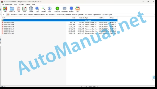
00 0290 605 0.pdf
00 0291 947 0.pdf
00 0294 062 4.pdf
00 0299 704 2.pdf
00 0299 705 4.pdf
00 0305 273 1.pdf
00 0290 605 0.pdf:
Introduction
Validity of instructions
Connection diagrams
13c Spreading of straw and chaff. Radial spreader with distributing features
13c Spreading of straw and chaff. Radial spreader with distributing features
Denominations
Table of measured values
Function Description
Spreading mode switch U039
Function Description
Occupation of the sockets
Connection List
Module occupancy
Module A51 – radial spreader
Denominations
Pin occupation
Alphabetical index
00 0294 062 4.pdf:
LEXION 600 – 510 From machine no.: 589 00018, 586 00918, 585 00358, 584 02256, 583 00868 – Technical systems, Electrical installation
Central electrical system (ZE)
Module occupancy
Module A6 – automatic air conditioning system
Module A7 – cabin fan, speed regulator
Module A8 – AUTOCONTOUR (CAC)
Module A9 – AUTOPILOT (ATP)
Module A10 – on-board reporter (BIF/CAB)
Module A13 – grain passage control (DKG)
Module A15 – electronic control of the CATERPILLAR engine (CAT C13,C12,C10, C9, 3126B)
Module A15 – electronic control of the CATERPILLAR engine (CAT C 6.6)
Module A15 – DAIMLER-CHRYSLER electronic engine control (DC)
Module A17 – adaptation of the ADM DAIMLER-CHRYSLER (DC) engine
Module A16 – reel regulation
Module A21 – quantimeter
Module A25 – regulation of the sieves
Module A27 – VARIO
Module A28 – spreader fan (VGS)
Module A30 – Cebis terminal
Module A33 – Sidefinder
Module A34 – grain tank
Module A37 – electrohydraulic switching (EHS) – 3-speed gearbox
Module A37 – electrohydraulic switching (EHS) – 2-speed gearbox
Module A38 – rotor (RIO)
Module A39 – feed regulation
Module A46 – regulation of the spreader plate (RIO)
Module A49 – propulsion module (EFA)
Module A51 – centrifugal distributor
Module A65 – GPS pilot terminal
Module A66 – GPS pilot module (GPB)
Module A79 – Drive Steering Axle Module (RAD)
Module A83 – 4-Trac Release Module
Connection diagrams 01a – 50a
01a Main voltage system supply, diesel engine starter motor
02a Start the diesel engine, adjust the diesel engine speed – CAT C13 ACERT, C9 ACERT (TIER III)
02b Starting the diesel engine, regulating the diesel engine speed – CAT C12, 3126B
02c Starting the diesel engine, regulating the diesel engine speed – CAT C6.6
02d Starting the diesel engine, adjusting the diesel engine speed – DC 502 LA
03a Diesel engine control
04a Road driving, circulation blocking valve (not with electro-hydraulic propulsion)
04b Road driving, circulation lock valve – with electrohydraulic drive (EFA)
05a Terminal, keyboard, rotary switch, printer (not with electro-hydraulic drive)
05b Terminal, keyboard, rotary switch, printer – with electrohydraulic drive (EFA)
06a CAN-Bus, module voltage supply, valid for CATERPILLAR diesel engines – C13, C12, C10, C9, 3126B
06b CAN-Bus, module voltage supply, valid for CATERPILLAR diesel engines – C 6.6
06c CAN-Bus, module voltage supply, valid for Daimler – Chrysler DC 502 LA B diesel engines
07a Switching of threshing devices
08a Adjustment of the concave / variator of the shelling cylinder
09a Adjustment of the rotor flaps / rotor variator
10a Fan variator
11th Regulation of sieves
12th Adjustment of the spreader plate
13a Chaff and straw spreading, spreader fan
13b Straw and chaff spreading – centrifugal spreader
14a Rotate the grain tank discharge tube
15a Grain tank unloading / grain tank unloading aid
16a Dividing knife switching, rapeseed
17a Spindle drive, reversing process drive, spindle quick stop
18a Spindle variator
19a Straw chopper – Standard chopper for LEXION 570 – 510
19b Straw chopper – Centrifugal distributor for LEXION 600 – 570
20a Raise/lower the front implement, transverse adjustment
21a Reel adjustment – standard cutterbar, folding cutterbar, MaxFlex soybean header
21b Reel adjustment – VARIO cutting mechanism
21c Conspeed corn header – folding the corn header, regulating the starting plates, laying corn augers
21d Rake up – drive, distributor adjustment
22a Reel variator
23a Adjustment of the cutting table (Vario), folding the cutting mechanism
23b Adjustment of the cutting table – MaxFlex
24th AUTOCONTOUR (CAC)
25a Speed control
26aMachine control
26bMachine control
27a Quanmeter / grain meter
28a AUTOPILOT – Laser system
28b AUTOPILOT – probe system
28c AUTOPILOT – GPS direction
29a Control of grain passage
30a Open/close grain tank (electrically), grain tank full indicator, rotating flashing lights
30b Open/close grain tank (hydraulically), grain tank full indicator, rotating flashing lights
31a Head cushioning
32a Four-wheel drive – Overdrive, fuel tank (not with electro-hydraulic drive)
32b Four-wheel drive – Overdrive, fuel tank – with electrohydraulic drive (EFA)
32cFour-wheel drive – drixluel tank
33a Cutting mechanism spring lock (only when equipped with spring-loaded head cylinders)
36th Flashing Light Team (Europe)
36b Flashing lights equipment (USA)
37a Windshield wipers, window washer equipment
38a Air conditioning equipment
38b Automatic air conditioning system
39a Cabin comfort equipment – driver’s seat
40a Additional sockets, safety controller
42a Propulsion and brake control – with electrohydraulic propulsion (EFA)
43a Electrohydraulic propulsion (EFA), “CRUISE PILOT” advance regulator
44a Electro-hydraulic gear shift (EHS), 3-speed gearbox
44b Electrohydraulic gear shift (EHS), 2-speed gearbox (not for LEXION – Montana*)
45a Switching main light, rear light, position light
46a Low beam, high beam, headlight switching
47a Working lighting I
48a Work lighting II
49a Sieve lighting, – grain tank, – return, horn, brake lights (not with electro-hydraulic propulsion)
49b Lighting of the sieves, – of the grain tank, – of the return, horn, brake ts – welectrohydraulic propulsion (EFA)
50a Instrument lighting, radio, mirror adjustment
Component Grid
Alphabetical index
0294 062.4
00 0299 704 2.pdf:
Technical systems – Electrical installation LEXION 600 – 510, up to machine no.: 589 00017, 586 00917, 585 00357, 584 02255, 583 00867
Structure of the connection diagrams
central electrical system
Central electrical system (LEXION 600-510)
Module occupancy
Module A6 – automatic air conditioning system
Module A7 – cabin fan, speed regulator
Module A8 – AUTOCONTOUR (CAC)
Module A9 – Autopilot (ATP)
Module A10 – on-board reporter (BIF/CAB)
Module A12 – revolution controller (DZW)
Module A13 – grain passage control (DKG)
Module A15 – electronic control of the CATERPILLAR engine (CAT C13,C12,C10, C9, 3126B)
Module A15 – DAIMLER-CHRYSLER electronic engine control (DC)
Module A17 – adaptation of the ADM DAIMLER-CHRYSLER (DC) engine
Module A16 – reel regulation
Module – quantimeter
dule A25 – regulation of the sieves
Module A27 – VARIO
Module A28 – spreader fan (VGS)
Module A30 – terminal
Module A33 – Sidefinder
Module A34 – grain tank
Module A35 – Montana 570-520 control – with external Montana control
Module A36 – Montana 570-520 gear preselection – with Montana external control
Module A37 – electrohydraulic switching (EHS) – 3-speed gearbox
Module A37 – electrohydraulic switching (EHS) – 2-speed gearbox
Module A38 – Rotor (RIO)
Module A42 – MONTANA GEN II Module – with integrated Monta control
Module A45 – propulsion hydraulic system brake restrictor (HBM)
Module A46 – regulation of the spreader plate (RIO)
Module A49 – Propulsion module (EFA)
Module A51 – centrifugal distributor
A65 Module – GPS Pilot Terminal
A66 Module – GPS Pilot Module (GPB)
Connection diagrams 01a – 50a
01a Main voltage system supply, diesel engine starter motor
02a Start the diesel engine, adjust the diesel engine speed – CAT C12, C10, C9, 3126B
02b Starting the diesel engine, adjusting the diesel engine speed – DC 502 LA
02c Starting the diesel engine, adjusting the diesel engine speed – DC 502 LA with electrohydraulic drive (EFA)
02d Starting the diesel engine, regulating the diesel engine speed – CAT C6.6
02e Starting the diesel engine, regulating the diesel engine speed – CAT C13 ACERT, C9 ACERT (TIER III)
03a Diesel engine control
04a Road driving, circulation blocking valve
04b Road driving, circulation lock valve – with electrohydraulic drive (EFA)
05a Terminal, keyboard, rotary switch, printer
05b Terminal, keyboard, rotary switch, printer – with electrohydraulic drive (EFA)
06a CAN-Bus, module voltage supply, valid for CATERPILLAR diesel engines – C12, C10, C9, 3126B
06b CAN-Bus, module voltage supply, valid for Daimler – Chrysler DC 502 LA diesel engines, – without electro-hydraulic propulsion (EFA)
06c CAN-Bus, module voltage supply, valid for CATERPILLAR diesel engines – C13 ACERT (TIER III), – with electro-hydraulic propulsion (EFA)
06d CAN-Bus, module voltage supply, valid for Daimler – Chrysler DC 502 LA diesel engines, – with electro-hydraulic propulsion (EFA)
06e CAN-Bus, module voltage supply, valid for CATERPILLAR diesel engines – C 6.6
06f CAN-Bus, module voltage supply, valid for CATERPILLAR diesel engines – C9 ACERT (TIER III)
07a Switching of threshing devices
08a Adjustment of the concave / variator of the shelling cylinder
09a Adjustment of the rotor flaps / rotor variator
10a Fan variator
11th Regulation of sieves
12th Adjustment of the spreader plate
13a Chaff and straw spreading, spreader fan – LEXION 580
13b Straw and chaff spreading – centrifugal spreader
14a Rotate the grain tank discharge tube
15a Grain tank unloading / grain tank unloading aid
16a Dividing knife switching, rapeseed
17a Spindle drive, reversing process drive, spindle quick stop
17b Spindle drive, reversing process drive, quick spindle stop – with electrohydraulic drive (EFA)
18a Spindle variator
19a Straw chopper
19b Straw chopper – fanless centrifugal chaff draft distributor
19c Straw chopper – centrifugal distributor with chaff draft fan
20a Raise/lower the front implement, transverse adjustment
20b Raise/lower the front implement, transverse adjustment – with electrohydraulic propulsion (EFA)
21a Reel adjustment, standard cutting mechanism, MaxFlex soybean header
21b Reel adjustment, VARIO cutting mechanism
21c Reel adjustment, folding cutting mechanism
21d Folding the corn header, regulating the starting plates, laying corn augers
21e Rake up – Drive, adjustment of the distributor
22a Reel variator
23a Adjustment of the cutting table (Vario), folding the cutting mechanism
23b Adjustment of the cutting table – MaxFlex
24th AUTOCONTOUR (CAC)
25a Speed control
26a Machine control
26b Machine control – with electrohydraulic drive (EFA)
27a Quanmeter / grain meter
28a AUTOPILOT – Laser system
28b AUTOPILOT – probe system
28c AUTOPILOT – GPS address
29a Control ofin passage
30a Oplose grain tank (electrically), grain tank full indicator, rotating flashing lights
30b Open/close grain tank (hydraulically), grain tank full indicator, rotating flashing lights
31a Head cushioning
32a Four-wheel drive, fuel tank
32b Four Wheel Drive – Overdrive, Fuel Tank
32c Four-wheel drive, fuel tank – with electrohydraulic drive (EFA)
32d Four-wheel drive – Overdrive, fuel tank – with electrohydraulic drive (EFA)
33a Cutting mechanism spring lock
36th Flashing Light Team (Europe)
36b Flashing lights equipment (USA)
37a Windshield wipers, window washer equipment
38a Air conditioning equipment
38b Automatic air conditioning system
39a Cabin comfort equipment – driver’s seat
40a Additional sockets, safety controller
42a Propulsion and brake control
42b Drive and brake control – with electrohydraulic drive (EFA) LEXION 600 TerraTrac
43rd Electrohydraulic propulsion (EFA)
44a Gear shift, electrohydraulic, 3-speed gearbox
44b Gear shift, electrohydraulic, 2-speed gearbox
45a Switching main light, rear light, position light
46a Low beam, high beam, headlight switching
47a Working lighting I
48a Work lighting II
49a Sieve lighting, – grain tank, – return, horn, brake lights
49b Lighting of the sieves, – of the grain tank, – of the return, horn, brake lights – with electrohydraulic propulsion (EFA)
50a Instrument lighting, radio, mirror adjustment
Component Grid
Alphabetical index
0299 704.2
00 0299 705 4.pdf:
LEXION 600 – 510 – Technical systems, Hydraulic installation
1 General hydraulic installation
1.1 General hydraulic installation
1.1.1 Oil tank (general hydraulic system)
1.1.2 Hydropumps
1.1.3 Hydromotors
1.1.4 Valve elements
1.2 Connection table, general hydraulic system
1.2.1 General hydraulic system connection table – machine with rotors
LEXION 600 – wheeled machine
1.2.2 General hydraulic system connection table – machineh rotors
LEXION 600 Terrac
1.2.3 General hydraulic system connection table, rotor machine
LEXION 580 to machine no. 586 00336 – with spreader fan
1.2.4 General hydraulic system connection table, rotor machine
LEXION 580 from machine no. 586 00337 – with spreader fan
1.2.5 General hydraulic system connection table, rotor machine
LEXION 580 from machine no. 586 00337 – with radial spreader
1.2.6 General hydraulic system connection table, rotor machine
LEXION 570 with standard chopper, up to machine no. 585 00162
1.2.7 General hydraulic system connection table, rotor machine
LEXION 570 with standard chopper from machine no. 585 00163
1.2.8 General hydraulic system connection table, rotor machine
LEXION 570 with centrifugal distributor, up to machine no. 585 00162
1.2.9 General hydraulic system connection table, rotor machine
LEXION 570 with centrifugal distributor, from machine no. 585 00163
1.2.10 General hydraulic system connection table, shaker machine
LEXION 560 – 510 up to machine no. 584 00895, 583 00298
1.2.11 General hydraulic system connection table, shaker machine
LEXION 560 – 510 from machine no. 584 00896, 583 00299 – with standard chopper
1.2.12 General hydraulic system connection table, shaker machine
LEXION 560 – 510 from machine no. 584 00896, 583 00299 – with radial spreader
Denominations
1.3 Multiple coupling
2 Steering hydraulic system
2.1 Steering hydraulic system connection tables
2.1.1 Steering hydraulic system connection table with AUTOPILOT – with concave adjustment with filling valve – LEXION 600 / 580 / 570
2.1.2 Steering hydraulic system connection table with AUTOPILOT – with concave adjustment without fill valve – LEXION 560 – 510
2.1.3 Steering hydraulic system connection table without AUTOPILOT
2.2 Steering function
2.2.1 Steering function
2.2.2 Steering function – Two-level orbitrol
2.3 AUTOPILOT
2.3.1 AUTOPILOT function right / left
3 Hydraulic operating system
3.1 Operating hydraulic system connection table
3.1.1 Connection table of the hydraulic system operator – rotor machine
3.1.3 Operation hydraulic system connection table, rotor machine
3.1.4 Operation hydraulic system connection table, rotor machine
3.1.6 Operation hydraulic system connection table, rotor machine
3.1.7 Operation hydraulic system connection table, rotor machine
3.1.8 Operation hydraulic system connection table, rotor machine
3.1.9 Operation hydraulic system connection table, rotor machine
3.1.10 Operation hydraulic system connection table, shaker machine
3.1.11 Operation hydraulic system connection table, shaker machine
3.1.12 Operation hydraulic system connection table, shaker machine
3.2 Main valve raise/lower head
3.2.1 Main valve
3.3 Concave regulation
3.3.1 Concave adjustment, LEXION 600 / 580 / 570 Hydro-pneumatic overload system with filling valve
3.3.2 Concave adjustment, LEXION 560 -510 Hydraulic overload system without filling valve
3.4 Regulation of the speed of the shelling cylinder
3.4.1 Regulation of the speed of the shelling cylinder
3.5 Rotate the spreader fan / centrifugal distributor / swath flap
3.5.1 Turn the spreader fan
3.5.2 Rotate the centrifugal distributor
3.5.3 Rotate the swath hatch
3.6 Rotate the discharge tube
3.6.1 Rotate the discharge tube
3.7 Regulation of the speed of the rotors
3.7.1 Regulation of the speed of the rotors
3.8 Instant head stop
3.8.1 Instantaneous spindle stop
3.9 Locking the cutting mechanism suspension springs
3.9.1 Locking the cutting mechanism suspension springs
3.10 Adjustment of the carrier/head speed speed
3.10.1 Adjustment of the speed of the conveyor / headstock
3.11 Open / close the grain tank (hydraulically) Help for unloading the grain tank
3.11.1 Open / close the grain tank (hydraulically)
3.11.2 Help for unloading the grain tank
3.12 Head adjustment
3.12.1 AUTO-CONTOUR (CAC) – transversal adjustment of the head – LEXION 580 – 510 up to machine no. 586 00336, 585 00162, 584 00895, 583 00298
3.12.2 AUTO-CONTOUR (CAC) – transversal adjustment of the head – LEXION 600 – 510 from machine no. 589 00011, 586 00337, 585 00163, 584 00896, 583 00299
3.13 Reverse the direction of travel of the head
3.14 Head cushioning
3.14.1 Headstock cushioning – with spring-loaded headstock cylinder
3.14.2 Headstock cushioning – with springless headstock cylinder (CAC II)
3.15 Tensioning the half-track running belt
3.15.1 Half-track tread tension
3.15.2 Half-track tread tension
3.16 Adjustment of the cutting frame (Montana)
3.17 Cutting angle regulation (Montana)
3.18 Service brake – refill brake retainer (Montana)
3.18.1 Fill the brake accumulator – LEXION 600 Terra Trac, LEXION Montana
4 Low pressure hydraulic system
4.1 Low pressure hydraulic installation – main functions
4.1.1 Connection table for the LEXION 600 low-pressure hydraulic system (wheeled machine)
4.1.2 Connection table for the LEXION 600 Terra Trac low-pressure hydraulic system
4.1.3 Connection table, low pressure hydraulic system LEXION 580 – 510
4.1.4 Low pressure hydraulic system pressure limiting valve
4.1.5 Electromagnetic valves of the low pressure hydraulic installation
4.1.6 Hydraulic cylinders of the low pressure hydraulic system
4.1.7 3-D Screen Box Control
4.1.8 Greasing the chains for unloading the grain tank
5 Electrohydraulic gear shift (EHS)
5.1 Connection diagram of the electro-hydraulic gear shift (EHS) LEXION 580 – 510
5.2 Wiring diagram of the LEXION 600 electro-hydraulic gear shift (EHS)
6 Straw and chaff spreader
6.1 Straw and chaff spreader
6.1.1 Connection board, straw and chaff spreader
6.1.2 Drive of the straw and chaff spreader
6.2 Spreader fan
6.2.1 Connection board, spreader fan (VGS)
6.2.2 Drive of the spreader fan (VGS)
6.3 Centrifugal distributor
6.3.1 Centrifugal distributor connection diagram
6.3.2 Centrifugal distributor – working/transport position
6.3.3 Centrifugal distributor – transport position
6.3.4 Centrifugal distributor – spreading plate drive
7 Cleaning the radiator
7.1 Rotating radiator screen
7.1.1 Connection board, radiator rotary screen
7.1.2 Drive of the radiator rotary screen
7.2 Flat radiator cleaning
7.2.1 Connection panel, flat radiator cleaning
7.2.2 Radiator flat cleaning drive
8 Hydraulic feed system
8.1 Hydraulic feed system – mechanical control
8.1.1 Connection diagram of the hydrostatic advance – with mechanical control – to machine no. 586 00336, 585 00162, 584 00895, 583 00298
8.1.2 Hydrostatic feed connection diagram – with mechanical control – from machine no. 586 00337, 585 00163, 584 00896, 583 00299
8.1.3 Hydropump assembly
8.1.4 Hydromotor assembly
8.1.5 Control of the hydrostatic feed retarding throttle (HBM) – up to machine no. 586 00336, 585 00162, 584 00895, 583 00298
8.1.6 Hydraulic drive brake restrictor control (HBM) – from machine no. 586 00337, 585 00163, 584 00896, 583 00299
8.2 Hydrostatic propulsion – with electronic control (EFA)
8.2.1 Hydrostatic propulsion connection diagram – with electronic control (EFA)
8.2.2 Hydrostatic propulsion connection diagram – with electronic control (EFA)
8.2.3 Propulsion – adjustment pump and adjustment motor
8.2.4 Adjustment, hydromotor speed sensor
8.2.5 Propulsion – adjustment pump and adjustment motor
8.3 Traction 4-Trac (4×4)
8.3.1 Connection diagram 4-Trac (4×4)
8.3.2 Connection diagram 4-Trac (4×4)
8.3.3 Connection diagram 4-Trac (4×4)
8.3.4 4-Trac (4×4) traction connection diagram
8.3.5 MUD-HOG valve group
8.3.6 POCLAIN radial piston hydromotor
8.3.7 4-Trac Overdrive
8.3.8 4-Trac LTA
8.3.9 4-Trac LTA
9 Axle hydraulic system (Montana)
10 Brake system
10.1 LEXION 600 brake system – wheeled machine
10.2 LEXION 600 Terra Trac brake system – half-track
10.3 LEXION-560 – 510 brake system
11 Standard cutting mechanism
11.1 Connection board, standard cutting mechanism
11.2 Vertical adjustment of the reel (standard cutting mechanism)
11.3 Horizontal adjustment of the reel (standard cutting mechanism)
11.4 Regulation of the reel speed (standard cutting mechanism)
11.5 Rapeseed saw drive (standard cutting mechanism)
12 Vario cutting mechanism
12.1 Connection board, Vario cutting table
12.2 Vertical adjustment of the reel (Vario cutting mechanism)
12.3 Horizontal adjustment of the reel (Vario cutting mechanism)
12.4 Regulation of the reel speed (Vario cutting mechanism)
12.5 Adjusting the cutting mechanism tray (Vario cutting mechanism)
12.6 Drive of the rapeseed saw (Vario cutting mechanism)
13 Folding cutting mechanism
13.1 Connection board, folding cutting mechanism
13.2 Vertical adjustment of the reel (folding cutting mechanism)
13.3 Horizontal adjustment of the reel (folding cutting mechanism)
13.4 Regulation of the reel speed (folding cutting mechanism)
13.5 Folding the cutting mechanism
14 Corn milking head
14.1 Connection board, Conspeed corn milking header / 6 rows (type 908)
14.2 Connection board, Conspeed corn milking header / 8 row (type 907)
14.3 Folding milking units / adjusting milking plates – Conspeed corn milking head
14.4 Regulation of the reel revolutions (Conspeed corn milking head)
15 MaxFlex cutting mechanism
15.1 MaxFlex cutting mechanism connection table
15.2 Vertical adjustment of the reel (MaxFlex cutting mechanism)
15.3 Horizontal reel adjustment (MaxFlex cutting mechanism)
15.4 Regulation of the reel speed (MaxFlex cutting mechanism)
15.5 Locking the cutting table (MaxFlex cutting mechanism)
Location of components
Component Grid
Alphabetical index
0299 705.4
John Deere Repair Technical Manual PDF
John Deere Repair Technical Manual PDF
John Deere Repair Technical Manual PDF
John Deere Repair Technical Manual PDF
John Deere Repair Technical Manual PDF
John Deere Transmission Control Unit Component Technical Manual CTM157 15JUL05
John Deere Repair Technical Manual PDF
John Deere Diesel Engines POWERTECH 2.9 L Component Technical Manual CTM126 Spanish
John Deere Repair Technical Manual PDF
John Deere Parts Catalog PDF
John Deere Tractors 7500 Parts Catalog CPCQ26568 30 Jan 02 Portuguese
John Deere Repair Technical Manual PDF
John Deere DF Series 150 and 250 Transmissions (ANALOG) Component Technical Manual CTM147 05JUN98

