Claas Lexion 600 (589) Combines Operator Manual EN
$50.00
- Model: Lexion 600 (589) Combines
- Type Of Manual: Operator Manual
- Language: EN
- Format: PDF(s)
- Size: 380 MB
File List:
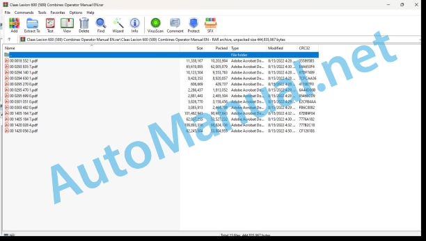
00 0018 552 1.pdf
00 0293 835 7.pdf
00 0294 140 1.pdf
00 0294 650 1.pdf
00 0295 270 0.pdf
00 0295 470 1.pdf
00 0295 699 0.pdf
00 0301 051 0.pdf
00 0303 482 0.pdf
00 1405 164 7.pdf
00 1405 184 7.pdf
00 1420 028 4.pdf
00 1420 056 2.pdf
00 0018 552 1.pdf:
TELEMATICS Website
Table of contents
1 About this Concise Operator’s Manual
1.1 Notes on the manual
1.1.1 Validity of manual
1.1.2 Notes regarding the Concise Operator’s Manual
1.1.3 Notes on warranty
2.1 Intended use
2.1.1 Proper use
3 Product description
3.1 Overview and method of operation
3.1.1 TELEMATICS product variants
3.1.2 TONI (TELEMATICS on implements)
3.1.3 Fleet View
3.1.4 TELEMATICS basic
3.1.5 TELEMATICS advanced
3.1.6 TELEMATICS professional
3.1.7 TELEMATICS app
4 Operating and control elements
4.1 TELEMATICS overview
4.1.1 Illustration conventions of buttons and navigation elements
4.1.2 Symbols and colours
4.2 Menu structure
4.2.1 Start screen
4.2.2 TELEMATICS website site map
4.2.3 Main menu overview
4.2.4
4.2.5
4.2.6
00 0294 140 1.pdf:
1 Introduction
1.1 General Information
1.1.1 How to use this manual
1.1.2 Validity of instructions
1.1.3 Rubber half-track identification plate
2 Specifications
2.1 CLAAS LEXION 600 Terra-Trac
2.1.1 Chassis
2.1.2 Tyres and tyre pressures
2.1.3 Torque settings of wheel bolts
2.1.4 Track width
2.1.5 Transport position / Working position
2.2 CLAAS LEXION 580 Terra-Trac
2.2.1 Chassis
2.2.2 Tyres and tyre pressures
2.2.3 Torque settings of wheel bolts
2.2.4 Track width
2.2.5 Transport position / Working position
2.3 CLAAS LEXION 570 Terra-Trac
2.3.1 Chassis
2.3.2 Tyres and tyre pressures
2.3.3 Torque settings of wheel bolts
2.3.4 Track width
2.3.5 Transport position / Working position
2.4 CLAAS LEXION 560 Terra-Trac
2.4.1 Chassis
2.4.2 Tyres and tyre pressures
2.4.3 Torque settings of wheel bolts
2.4.4 Track width
2.4.5 Transport position / Working position
3 Safety precautions
3.1 Important
3.1.1 Important information
3.1.2 Proper use
3.1.3 Identification of warning and danger signs
3.2 Safety decals
3.2.1 General information on safety decals
3.2.2 Safety decals
000 516 039 0 (22)
000 516 064 0 (22)
000 515 139 1 (50)
4 Package list
4.1 Rubber half-track
4.1.1 Pack joint 000 764 258 1 (type 589), 000 764 202 1 (type 586/584), 000 764 346 0 (type 585)
5 Mounting
5.1 Rubber half-track
5.1.1 Fitting the rubber half-tracks
5.1.2 Installing the front ladder
5.1.3 Aligning the rubber tracks
Preparing for temperature measurement
Carry out a test drive
Measure the temperatures of the guide blocks
Align the rubber track
Example: Aligning the rubber track
6 Fieldwork
6.1 Operation
6.1.1 Check rubber track tension
6.1.2 Ladder while driving on slopes
6.1.3 Folding the ladder steps
6.1.4 Towing a machine with hydraulic parking brake and defective engine
7 Maintenance
7.1 Important maintenance instructions
7.1.1 Important maintenance instructions and safety rules
7.2 Maintenance schedules
7.2.1 Maintenance chart for rubber half-track
7.2.2 Lubricants
7.2.3 Aligning the rubber tracks
Preparing for temperature measurement
Carry out a test drive
Measure the temperatures of the guide blocks
Align the rubber track
Example: Aligning the rubber track
7.2.4 Tension the rubber tracks
Preparations
Bleeding and pressurising the system
7.2.5 Oil change / Oil level check
Oil level checks
Oil change
7.2.6 Wheel bolts and mounting bolts – torque settings
7.2.7 Inspection of rubber track / track roller unit
8 Lubrication chart
8.1 Lubrication points
8.1.1 Greasing cycles
Lubricant symbols in figures
8.1.2 Lubrication points – 50 h on the left
8.1.3 Lubrication points – 50 h on the right
8.1.4 Lubrication points – 100 h on the left
8.1.5 Lubrication points – 100 h on the right
8.1.6 Lubrication points – 500 h on the left
8.1.7 Lubrication points – 500 h on the right
00 0294 650 1.pdf:
1 Introduction
1.1 General Information
1.1.1 How to use this manual
Texts and figures
Document structure based on subassemblies
Search and find
Directions
1.1.2 Validity of instructions
1.1.3 Rubber half-track identification plate
2 Specifications
2.1 CLAAS LEXION 600 Terra-Trac
2.1.1 Chassis
2.1.2 Tyres and tyre pressures
2.1.3 Torque settings of wheel bolts
2.1.4 Track width
2.1.5 Transport position / Working position
2.2 CLAAS LEXION 580 Terra-Trac
2.2.1 Chassis
2.2.2 Tyres and tyre pressures
2.2.3 Torque settings of wheel bolts
2.2.4 Track width
2.2.5 Transport position / Working position
2.3 CLAAS LEXION 570 Terra-Trac
2.3.1 Chassis
2.3.2 Tyres and tyre pressures
2.3.3 Torque settings of wheel bolts
2.3.4 Track width
2.3.5 Transport position / Working position
2.4 CLAAS LEXION 560 Terra-Trac
2.4.1 Chassis
2.4.2 Tyres and tyre pressures
2.4.3 Torque settings of wheel bolts
2.4.4 Track width
2.4.5 Transport position / Working position
3 Safety precautions
3.1 Important
3.1.1 Important information
3.1.2 Intended use
3.1.3 Identification of warning and danger signs
3.2 Safety decals
3.2.1 General information on safety decals
3.2.2 Safety decals
000 516 039 0 (22)
000 516 064 0 (22)
000 515 139 1 (50)
4 Package list
4.1 Rubber half-track
4.1.1 Pack joint 000 764 258 1 (type 589), 000 764 202 1 (type 586/584), 000 764 346 0 (type 585)
5 Mounting
5.1 Rubber half-track
5.1.1 Fitting the rubber half-tracks
5.1.2 Installing the front ladder
5.1.3 Aligning the rubber tracks
Carry out a test drive
Measure the temperatures of the guide blocks
Align the rubber track
Example: Aligning the rubber track
6 Fieldwork
6.1 Operation
6.1.1 Check rubber track tension
6.1.2 Ladder while driving on slopes
6.1.3 Folding the ladder steps
6.1.4 Rotating the front ladder
6.1.5 Towing a machine with hydraulic parking brake and defective engine
7 Maintenance
7.1 Important maintenance instructions
7.1.1 Important maintenance instructions and safety rules
7.2 Maintenance schedules
7.2.1 Maintenance chart for rubber half-track
7.2.2 Lubricants
7.2.3 Aligning the rubber tracks
Carry out a test drive
Measure the temperatures of the guide blocks
Align the rubber track
Example: Aligning the rubber track
7.2.4 Tension the rubber tracks
Preparations
Bleeding and pressurising the system
7.2.5 Oil change / Oil level check
Oil level checks
Oil change
7.2.6 Inspection of rubber track / track roller unit
8 Lubrication chart
8.1 Lubrication points
8.1.1 Greasing cycles
8.1.2 Lubrication points – 100 h on the left
8.1.3 Lubrication points – 100 h on the right
8.1.4 Lubrication points – 500 h on the left
8.1.5 Lubrication points – 500 h on the right
00 0295 270 0.pdf:
1 Einleitung
1.1 Allgemeine Hinweise
1.1.1 Handling of the Anleitung
1.1.2 Gültigkeit der Anleitung
2 Vor Inbetriebnahme
2.1 Mähdrescher fahren mit mechanischer / elektro-hydraulischer Fahrbetätigung
2.1.1 Schaltvorgang EHS-Notbetrieb über Gang-Taster (ab Maschinen-Nr. …)
3 Wartung – Grundmaschine
3.1 Schmierstofftabellen
3.1.1 Schmierstoffe
4 Wartung Engine
4.1 Wartungstabellen
4.1.1 Wartungstabelle CATERPILLAR Engine
1 Introduction
1.1 General Information
1.1.1 How to use this manual
1.1.2 Validity of instructions
2 Prior to operation
2.1 Driving the combine with mechanical / electro-hydraulic ground drive control
2.1.1 EHS emergency operation shifting proceduring the gear touch sensor (from serial no. …)
3 Maintenance – Basic machine
3.1 Lubricants charts
3.1.1 Lubricants
4 Engine maintenance
4.1 Maintenance schedules
4.1.1 CATERPILLAR engine maintenance schedule
1 Introduction
1.1 General advice
1.1.1 Use of the notice
1.1.2 Validity of the notice
2 Avant la mise en service
2.1 Conduite de la moissonneuse-batteuse avec commande mécanique/électrohydraulique d’avancement
2.1.1 Processus de passage des vitesses en servicing de secaurs EHS au moyen de la touche rapport (à de la machine N˚ …)
3 Entretien – basic machine
3.1 Tableaux des lubricants
3.1.1 Lubricants
4 Engine maintenance
4.1 Tableaux d’entertien
4.1.1 CATERPILLAR engine maintenance table
1 Introduction
1.1 General indications
1.1.1 Application of the user manual
1.1.2 Validity of the user manual
2 Prima della messa in exercise
2.1 Advancement of the mietitrebbia with mechanical command / hydraulic electric
2.1.1 In this button you can starEHS emergency using a button (from the machine No. …)
3 Maintenance – base machine
3.1 Lubricating tab
3.1.1 Lubricants
4 Motor maintenance
4.1 Maintenance tab
4.1.1 CATERPILLAR engine maintenance table
1. Introduction
1.1 General instructions
1.1.1 Using the instructions
1.1.2 Validity of instructions
2 Before start-up
2.1 Driving the combine with a mechanical / electro-hydraulic feed drive
2.1.1 EHS gear changing process in emergency operation, using the gear button (from machine no. …)
3 Maintenance – Base machine
3.1 Lubricant tables
3.1.1 Lubricant
4 Engine maintenance
4.1 Maintenance tables
4.1.1 CATERPILLAR engine maintenance table
00 0295 470 1.pdf:
1 An-/Abkuppeln Anhänger
1.1 Hinweise zum An-/Abkuppeln von Anhängern
1.1.1 Allgemeine Hinweise
1.1.2 Allgemeine Sicherheitshinweise
1.1.3 Anhänger ankuppeln
1.1.4 Anhänger abkuppeln
1 Hitching/unhitching a trailer
1.1 Information about hitching/unhitching trailer 1.1.1 General information
1.1.2 General safety instructions
1.1.3 Hitching the trailer
1.1.4 Unhitching the trailer
1 Atteler / deteler a trailer
1.1 Conseils pour atteler / deteler the trailers
1.1.1 General councils
1.1.2 General safety advice
1.1.3 Workshop the trailer
1.1.4 Deteler the trailer
1 Hooking / unhooking the trailer
1.1 Instructions for hooking and unhooking the trailer
1.1.1 General warning
1.1.2 General safety rule
1.1.3 Hooking up the trailer
1.1.4 Sgancio del rimorchio
1 Hook/unhook the trailer
1.1 Indications relating to hooking/unhooking trailers
1.1.1 General indications
1.1.2 General security measures
1.1.3 Hitch the trailer
1.1.4 Unhook the trailer
1 Coupling / uncoupling trailer
1.1 Indications relating to the coupling / uncoupling of trailers
1.1.1 General indications
1.1.2 General safety instructions
1.1.3 Attach trailer
1.1.4 Uncoupling or towing
1 Aan-/afkoppelen van tänders
1.1 Aanwijzingen bj het aan-/afkoppelen van tänders
1.1.1 General instructions
1.1.2 General safety instructions
1.1.3 Aanhanger aankoppelen
1.1.4 Aanhanger afkoppelen
1 Til-/frakoppling af anhænger
1.1 Anvisings til til-/frakoppling af anhængere
1.1.1 General notices
1.1.2 General safety instructions
1.1.3 Tilkoppling af anhänger
1.1.4 Frakoppling af anhänger
1 Till-/frånkällung av släpvagn
1.1 Anvisningar för till-/frånkolloppung av släpvagnar
1.1.1 General instructions
1.1.2 General safety precautions
1.1.3 Tillkoppling av släpvagn
1.1.4 Disconnecting the trailer
1 Til-/frakoppling av tilhenger
1.1 Information on til-/frakoppling av tilhengere
1.1.1 General notices
1.1.2 General security information
1.1.3 Koble på tilhenger
1.1.4 Koble fra tilhengeren
1 Perävaunun täkkäminen/irrotatänä
1.1 Perävaunun küppä-/irrotusohjeet
1.1.1 Generality
1.1.3 Vehicle coupling
1.1.4 Perävaunun irrotus
1 Piekabes piekabinâ²ana/atkabinbr piekabju piekabinâ²anu/atkabinâ²anu
1.1.1 Vispârîgie norâdîjumi
1.1.2 Vispârîgie dro²îbas norâdîjumi
1.1.3 Piekabes piekabinâ²ana
1.1.4 Piekabes atkabinâ²ana
1 Priekabø prikabinimas ir atkabinimas
1.1 Nurodymai priekaboms prikabinti ir atkabinti
1.1.1 Instructions
1.1.3 Priekabos prikabinimas
1.1.4 Connecting Priekabos
1.1.1 Üldised juhised
1.1.2 Üldised saifsjuhised
1.1.4 Haagise lahtiühendamine
1 Do-/od¸¶czanie przycepy
1.1 Wżczówki dotycz¶ce do-/od¸¶czania przyczep
1.1.1 General instructions
1.1.2 General safety tips
1.1.3 Do¸¶czanie przycepy
1.1.4 Od¸¶czanie przycepy
1 Çàêà÷âàíå/îòêà÷âàíå íà ²åìà²êå
1.1 ÓêàçàíèØ çà çàêà÷âàíå/îòêà÷âàíå íà ²åìà²êåòà
1.1.1 Îáùè óêàçàíèØ
1.1.2 Îáùè èíñò²óêöèè çà áåçîïàñíîñò
1.1.3 Çåêà÷âàíå íà ²åìà²êå
1.1.4 Îòêà÷âàíå íà ²åìà²êåection
1.1.4 Personal disconnection
1 Cuplarea and decuplarea remorcii
1.1 Instruc iuni pentru cuplarea și decuplarea remorcilor
1.1.1 Indicate ii general
1.1.2 General safety instruction at work
1.1.3 Couplarea remorcii
1.1.4 Decuplaria remorcii
1 ÓÆíäåóç/Á²ïóÆíäåóç ñõìïõëêïÆìåíïõ
1.1 Õ²ïäåßîåéò ãéá ôç óÆíäåóç/á²ïóÆíäåóç ñõìïõëêïÆìåíùí
1.1.1 ÃåíéêÅò ïäçãßåò
1.1.2 ÃåíéêÅò ïäçãßåò áóöáëåßáò
1.1.3 ÓÆíäåóç êïôóáäüñïõ
1.1.4 Á²ïóÆíäåóç ôïõ ñõìïõëêïÆìåíïõ
1 A pótkocsi fel- / lesköpa
1.1 Utasítás a pótkocsik fel- / leszállához
1.1.1 General instructions
1.1.2 General safety instructions
1.1.3 A pótkocsi (pótkocsi) felszóksi
1.1.4 A pótkocsi (pótkocsi) leszpóksi
1 Spajanje/odvajanje påres
1.1 Napomene uz spoženje/odvajanje prálakas
1.1.1 Opæenite napomene
1.1.2 Opæenite securi Vðobeconné bezpeènostné instructions
1.1.3 Návesu: Pripojenie
1.1.4 Odpojenie návesu
1 Priklop/odklop trailers
1.1 Instructions for priklop/odklop prikolic
1.1.1 Sploðna navoda
1.1.2 Exploding safety warning
1.1.3 Priklop trailers
1.1.4 Priklop trailers
1 Zakaèivanje/otkaèivanje tähälä
1.1 Instructions for the trailer
1.1.1 Opðte napomene
1.1.2 Choose safety instructions
1.1.3 Zakaèiti prikolicu
1.1.4 Otkaèiti prikolicu
1 Ïîäñîåäèíåíèå/îòñîåäèíåíèå ï²èöåïà
1.1 ÓêàçàíèØ ïî ïîäñîåäèíåíè /îòñîåäèíåíè ï²èöåïîâ
1.1.1 Îáùèå óêàçàíèØ
1.1.2 Îáùèå óêàçàíèØ ïî áåçîïàñíîñòè
1.1.3 ϲèñîåäèíåíèå ï²èöåïà
1.1.4 Îòñîåäèíèòü ï²èöåï
1 Römork ba²lama/çözme
1.1 Römork ba²lama/çözme ile ilgidi bilgiler
1.1.1 General information
1.1.2 General security uyarÆlarÆ
1.1.3 Römork ba²lamaLAAS CEBIS on-board information system
2.1.1 CEBIS General information
2.2 Controls and displays
2.2.1 Keypad
2.2.2 Rotary switch and direct menu
2.2.3 Vehicle control display
2.2.4 Harvest display
2.2.5 Main menu
2.2.6 Prior to initial commissioning
2.2.7 Menu Settings / Front attachment
2.2.8 Menu Settings / Diesel engine
2.2.9 Menu Settings / Speeds
2.2.10 Menu Settings / Secondary separation
2.2.11 Settings menu / Autopilot
2.2.12 Settings menu / CEBIS
2.2.13 Front attachment menu
2.2.14 Reel menu
2.2.15 No. of partial widths menu
2.2.16 Driving menu
2.2.17 Crop setting menu
2.2.18 Yield measuring menu
2.2.19 Recorder menu
2.2.20 Maintenance menu
2.2.21 Reference values for pulses per 100m
3 Prior to operation
3.1 CRUISE PILOT
3.1.1 Learning zero throughput
3.1.2 Preselecting the CRUISE PILOT strategy
3.1.3 Switch on CRUISE PILOT
3.1.4 Switch off CRUISE PILOT
3.1.5 Saving the cruise control ground speed (km/h)
3.1.6 Changing the cruise control ground speed (km/h)
3.1.7 Saving the throughput (t/h) of the crop
3.1.8 Changing the throughput (t/h) of the crop
3.1.9 CRUISE PILOT – driving behaviour when emptying the grain tank
4 Operation – Basic machine
4.1 Cab / Operator’s platform
4.1.1 Cutting height control
4.1.2 Saving the ground pressure
4.1.3 Saving the cutting height
00 0301 051 0.pdf:
PROFI CAM 3
Table of contents
1 Introduction
1.1 Notes on the manual
1.1.1 Validity of manual
1.1.2 Information about this Operator’s Manual
1.1.3 Symbols and notes
1.1.4 Optional equipment
1.1.5 Qualified specialist workshop
1.1.6 Maintenance information
1.1.7 Warranty notes
1.1.8 Spare parts and technical questions
1.2 Intended use
1.2.1 Intended use
1.2.2 Reasonably foreseeable misuse
2.1 Identifying warnings
2.1.1 Hazard signs
2.1.2 Signal word
2.2 Safety rules
2.2.1 Meaning of Operator’s Manual
2.2.2 Observing safety decals and warnings
2.2.3 Optional equipment and spare parts
3 Product description
3.1 Overview and method of operation
3.1.1 How the PROFI CAM works
3.2 Identification plates and identification number
3.2.1 Position of identification plates
3.2.2 Explanation of PROFI CAM identification plate
3.3 Information on the product
3.3.1 CE marking
4 Operating and control elements
4.1 Camera system
4.1.1 Camera system monitor
4.2 Menu structure
4.2.1 Main menu
4.2.2
4.2.3
4.2.4
4.2.5
4.2.6
5 Technical specifications
5.1 PROFI CAM
5.1.1 Monitor
5.1.2 Camera
5.1.3 Switch box
5.1.4 Degree of protection against foreign bodies and water
6 Preparing the product
6.1 Shutting down and securing the machine
6.1.1 Switching off and securing the machine
6.2 Prior to operation
6.2.1 Carry out prior to operation
6.2.2 Installing the sun protection
6.2.3 Aligning the camera
6.2.4 Connecting the camera electrics
7 Operation
7.1 Monitor
7.1.1 Switching on the monitor
7.1.2 Calling up the menu
7.1.3 Setting a menu item
7.1.4 Setting the image orientation
7.1.5 Setting automatic screen darkening
7.1.6 Image mirroring
7.1.7 Setting the trigger view
7.1.8 Setting the follow-up time for trigger view
7.1.9 Setting the display mode
7.1.10 Activating/deactivating a display mode
8 Faults and remedies
8.1 Electrical and electronic system
8.1.1 Overview of problems on PROFI CAM camera system
8.1.2 Replacing the switch box fuse
9 Maintenance
9.1 Maintenance intervals
9.1.1 Every 10 operating hours or daily
9.2 Camera system
9.2.1 Checking the camera system for dirt
9.2.2 Cleaning the camera
9.2.3 Cleaning the switch box
9.2.4 Cleaning the monitor
10 Placing out of operation and disposal
10.1 General Information
10.1.1 Putting out of operation and disposal
11 Technical terms and abbreviations
11.1 Abbreviations
11.1.1 Units
11.1.2 Abbreviations
11.1.3 Technical terms
00 0303 482 0.pdf:
PROFI CAM 4
Table of contents
1 Introduction
1.1 Notes on the manual
1.1.1 Validity of manual
1.1.2 Information about this Operator’s Manual
1.1.3 Symbols and notes
1.1.4 Optional equipment
1.1.5 Qualified specialist workshop
1.1.6 Maintenance information
1.1.7 Notes on warranty
1.1.8 Spare parts and technical questions
1.2 Intended use
1.2.1 Intended use
1.2.2 Reasonably foreseeable misuse
2.1 Identifying warnings
2.1.1 Hazard signs
2.1.2 Signal word
2.2 Safety rules
2.2.1 Meaning of Operator’s Manual
2.2.2 Structural changes
2.2.3 Optional equipment and spare parts
2.2.4 Operation only following proper putting into operation
2.2.5 Technical status
2.2.6 Respecting technical limit values
Respecting technical limit values
2.2.7 Hazards when driving on roads and fields
3 Product description
3.1 Overview and method of operation
3.1.1 How the PROFI CAM works
3.2 Identification plates and identification number
3.2.1 Identification plates
3.3 Information on the product
3.3.1 CE marking
4 Operating and display elements
4.1 Camera system
4.1.1 Camera system monitor
4.1.2 CEBIS
4.2 Menu structure
4.2.1 Main menu
4.2.2
4.2.3
4.2.4
4.2.5
4.2.6
5 Technical specifications
5.1 PROFI CAM
5.1.1 Monitor
5.1.2 Camera
5.1.3 Switch box
6 Preparing the product
6.1 Switching off and securing the machine
6.1.1 Switching off and securing the machine
6.2 Prior to putting into operation
6.2.1 Carry out prior to operation
6.2.2 Installing the sun protection
6.2.3 Aligning the camera
7 Operation
7.1 Monitor
7.1.1 Switching on the monitor
7.1.2 Calling up the menu
7.1.3 Setting a menu item
7.1.4 Setting the image orientation
7.1.5 Setting automatic screen darkening
7.1.6 Image mirroring
7.1.7 Setting the trigger view
7.1.8 Setting the follow-up time for trigger view
7.1.9 Setting the display mode
7.1.10 Activating/deactivating a display mode
8 Faults and remedies
8.1 Electric and electronic system
8.1.1 Overview of problems on PROFI CAM camera system
9 Maintenance
9.1 Maintenance intervals
9.1.1 Every 10 operating hours or daily
9.2 Camera system
9.2.1 Checking the camera system for dirt
9.2.2 Cleaning the camera
9.2.3 Cleaning the switch box
9.2.4 Cleaning the monitor
10 Putting out of operation and disposal
10.1 General information
10.1.1 Putting out of operation and disposal
11 Technical terms and abbreviations
11.1 Abbreviations
11.1.1 Units
11.1.2 Abbreviations
11.1.3 Technical terms
00 1405 164 7.pdf:
Table of contents
1 Introduction
1.1 General information
1.1.1 Validity of Manual
1.1.2 Information about this Operator’s Manual
1.1.3 Symbols and notes
1.1.4 Optional equipment
1.1.5 Qualified specialist workshop
1.1.6 Maintenance notes
1.1.7 Notes on warranty
1.1.8 Spare parts and technical questions
1.1.9 Licensing for road traffic
Sample report
Clearance certificate
General operating permit
1.2 Intended use
1.2.1 Intended use
1.2.2 Reasonably foreseeable misuse
2.1 Identifying warnings
2.1.1 Hazard signs
2.1.2 Signal word
2.2 Safety rules
2.2.1 Meaning of Operator’s Manual
2.2.2 Update of terminal software
2.2.3 Requirements made on all persons working with the product
2.2.4 Hazard areas
Hazard areas
2.2.5 Interaction between the control terminal and the machine or tractor
2.2.6 Structural changes
2.2.7 Optional equipment and spare parts
2.2.8 Use of USB devices
2.2.9 Operation only following proper putting into operation
2.2.10 Technical status
2.2.11 Hazard from damage on the product
2.2.12 Respecting technical limit values
Respecting technical limit values
2.2.13 Preparing the product for road travel
2.2.14 Hazards when driving on the road with an ISOBUS implement
Switching on the terminal during road travel.
2.2.15 Hazards when driving on the road and on the field
2.2.16 Electrocution by electrical system
2.2.17 Potentially fatal electric shock from overhead lines
2.2.18 Liquids under pressure
2.2.19 Maintenance operations and repair work
2.2.20 Driving with the GPS PILOT
Road travel
2.2.21 Working with Task Control* and Section Control*
3 Product description
3.1 Overview and method of operation
3.1.1 Overview of GPS PILOT – Hydraulic system
3.1.2 Overview of GPS PILOT – Steer ready
3.1.3 Overview of GPS PILOT FLEX
3.1.4 Overview of GPS PILOT ex works
3.1.5 Overview of the S10 terminal
3.1.6 Overview of navigation computer (ECU)
3.1.7 Electric steering wheel
3.1.8 Overview of correction signals
EGNOS/WAAS/MSAS
Omnistar HP / XP / G2
RTK FIELD BASE and BASELINE HD
RTK FARM BASE
3.1.9 Module overview
BASELINE HD
RTK FIELD BASE
RTK (Motorola)
RTK FARM BASE
3.2 Safety devices
3.2.1 Automatic cut-out when the maximum speed is exceeded
3.2.2 Automatic cut-out when the speed falls below the minimum
3.2.3 Seat contact switch
3.2.4 Manual override
Electric steering wheel
3.3 Optional equipment
3.3.1 GPS L2*
3.3.2 GLONASS*
3.3.3 TURN IN*
3.3.4 AUTO TURN*
3.3.5 Task Control*
Task Control Basic*
Task Control Geo*
3.3.6 Section Control*
3.4 Identification plates and identification numbers
3.4.1 GPS PILOT identification plate
3.4.2 Identification plate of terminal
3.4.3 Identification plate of navigation controller
4 Operating and display elements
4.1 GPS PILOT
4.1.1 Master switch and drive switch
4.2 Overview of the S10 terminal
4.2.1 Layout conventions of buttons and displays
4.3 GPS PILOT menu structure
4.3.1 Start menu
Start menu without Task Control*
Start menu with Task Control*
4.3.2 Menu overview
4.3.3 Overview of display field
4.3.4
4.3.5
4.3.6
John Deere Repair Technical Manual PDF
John Deere Repair Technical Manual PDF
John Deere Repair Technical Manual PDF
John Deere Repair Technical Manual PDF
John Deere Repair Technical Manual PDF
John Deere 16, 18, 20 and 24HP Onan Engines Component Technical Manual CTM2 (19APR90)
John Deere Parts Catalog PDF
John Deere Harvesters 8500 and 8700 Parts Catalog CPCQ24910 Spanish
John Deere Repair Technical Manual PDF
John Deere Repair Technical Manual PDF
John Deere Repair Technical Manual PDF

