Claas Lexion 630-620 (C73) Combines Repair Manual FR
$100.00
- Model: Lexion 630-620 (C73) Combines
- Type Of Manual: Repair Manual
- Language: FR
- Format: PDF(s)
- Size: 288 MB
File List:
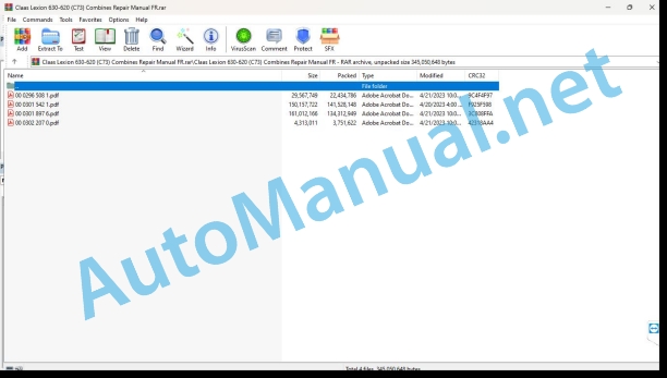
00 0296 508 1.pdf
00 0301 542 1.pdf
00 0301 897 6.pdf
00 0302 207 0.pdf
00 0296 508 1.pdf:
LEXION 770 – 620
Contents
Introduction
General informations
Validity of the notice
Use of the Notice
Texts and illustrations
Classification by module structure
Seek and find
Directions
Abbreviations
Specialized terms
General repair tips
Technical specifications
Tips for correct repair
Self-locking screws
Liquid screw brake
Steel roller chains
Chain closing link
Conical ring connections
Disassembly
Assembly
Heel pin connections
Disassembly
Assembly
Clamp ring bearing
Disassembly
Assembly
Clamp sleeve bearing
Disassembly
Assembly
Clamping sleeve
Disassembly
Assembly
Circlips
Threaded fittings with cutting ring
To screw
Sealing failure of the cutting ring connection
Bicone ring screw connections
Hydraulic flexible lines
Hose routing
Treatment of sealing surfaces
Spare parts
Tightening torques
Tightening torques for metric coarse threads
Tightening torques for metric fine pitch threads
Tightening torques for hydraulic screw connections and air conditioning system screw connections with bicone ring and O-ring DIN 3865
Tightening torques for hydraulic connections with cutting ring DIN 3861
Tightening torques for SDS hydraulic screwed sleeve
Tightening torques for hydraulic swivel threaded connections
Tightening torques for hollow screws DIN 7643
Tightening torques for SDE adjustable screwed hydraulic coupling
Tightening torques for brake line screw connections
Tightening torques for tangent screw clamps
Tightening torques for spring-controlled tangent screw clamps
Tightening torques for tires
CCN explanation
CCN (CLAAS Component Number)
Electrical standard
Hydraulic standard
CCN (CLAAS Component Number)
Security
General informations
Important
Marking of warnings and dangers
General safety instructions and accident prevention regulations
First aid measures
Risk of injury from hydraulic fluid
Exit the machine
Shutting down the machine
Place the machine on jack stands
Adjustment and maintenance work
Welding work
03 Chassis
0315 Drive axle
Drive axle
Technical characteristics
Axle body
Technical characteristics
Assembly tips
Axle slide
Preparing for work
Special tool
Technical characteristics
Disassemble
To assemble
To set down
Wheel hub
Preparing for work
Special tool
Technical characteristics
Disassemble
To assemble
To set down
Differential
Preparing for work
Special tool
Technical characteristics
Disassemble
To assemble
To set down
Adjust the axial play of the coupling claws
Preparing for work
Special tool
Technical characteristics
Disassemble
To assemble
To set down
Hydraulic Gear Shift Cylinder (3063)
Technical characteristics
Drive Shaft Mounting Tips
Tips for fitting seals
0330 Rear wheel steering axle
Identify the drive wheel steering axle
Drive wheel steering axle
Technical characteristics
To set down
Axle body
Preparing for work
Special tool
Technical characteristics
Disassemble
To assemble
To set down
Wheel hub
Preparing for work
Special tool
Technical characteristics
Remove the complete wheel hub
Completely install the wheel hub
Disassemble
To assemble
Preparing for work
Special tool
Technical characteristics
To set down
Half shafts
Technical characteristics
To set down
Tie rods
Preparing for work
Special tool
Technical characteristics
To set down
Adjust track and steering angle
Axle Drive Valve Block
Technical characteristics
To set down
Hydraulic axle drive motor (2003, 2004)
Preparing for work
Special tool
Technical characteristics
To set down
0330 Rear wheel steering axle
Identify the drive wheel steering axle
Drive wheel steering axle
Special tool
Technical characteristics
To set down
Axle body
Preparing for work
Special tool
Technical characteristics
Valid for tire pressure adjustment system
Disassemble
To assemble
To set down
Valid for tire pressure adjustment system
Wheel hub
Preparing for work
Special tool
Technical characteristics
Remove the complete wheel hub
Valid for tire pressure adjustment system
Completely install the wheel hub
Valid for tire pressure adjustment system
Disassemble
To assemble
Preparing for work
Special tool
Technical characteristics
To set down
Half shafts
Preparing for work
Special tool
Technical characteristics
To set down
Tie rods
Preparing for work
Technical characteristics
To set down
Adjust track and steering angle
Differential
Preparing for work
Technical characteristics
Disassemble
To assemble
Differential
Preparing for work
Technical characteristics
Disassemble
To assemble
To set down
Axle Drive Valve Block
Technical characteristics
Assembly tips
All-wheel drive coupling coupling cylinder (3002)
Technical characteristics
Assembly tips
Axle Drive Hydraulic Motor (2068)
Preparing for work
Technical characteristics
To set down
0365 Tire pressure adjustment system
Tire pressure adjustment system
Preparing for work
Special tool
Technical characteristics
To set down
0370 Tilt regulation
Hydraulic tilt regulation cylinder
Preparing for work
Technical characteristics
04 Brake
0405 Service brake
Braking mechanism
Technical characteristics
To set down
Accumulator cylinder
Preparing for work
Technical characteristics
To set down
Basic adjustment of cylinder stroke
Check cylinder stroke
Disable the brake
Activate the brake
05 Management
0505 Steering
Hydraulic steering cylinder (3023)
Preparing for work
Technical characteristics
To set down
Hydraulic steering cylinder (3023)
Technical characteristics
To set down
0510 Automatic steering
AUTO PILOT steering angle sensor (B006)
Technical characteristics
AUTO PILOT steering angle sensor (B006)
Technical characteristics
00 0301 542 1.pdf:
Mercedes-Benz OM936LA(Levels IV and V)
Contents
Introduction
General instructions
Validity of the notice
Use of the instructions
Texts and illustrations
Plan with module structure
Seek and find
Steering Specifications
Abbreviations
Specialized terminology
General repair instructions
Technical characteristics
Tips for correct repair
Self-locking screws
Liquid screw brake
Steel roller chains
Quick hitch
Type E quick coupler with spring
Type G quick coupler with wire
Type S quick coupler with pins
Assemblies using conical ring
Disassembly
Assembly
Heel pin assemblies
Assembly
Clamp ring bearing
Disassembly
Assembly
Clamp sleeve bearing
Assembly
Clamping sleeve
Removal of version A
Submission of version B
To set down
Clamping sleeve version A
Clamping sleeve version B
Circlips
Cutting ring fittings
To screw
Leaky cutting ring fittings
Sealing Cone Fittings
Hydraulic flexible lines
Passage of hoses
Treatment of sealing surfaces
Spare parts
Tightening torques
Tightening torques for metric ISO threads
Tightening torques for metric fine pitch threads
Tightening torques for screw connections with bicone connection and hydraulic connections with flexible sealing gasket
Tightening torques for hydraulic connections with cutting ring
Tightening torques for hydraulic screwed coupling SDS form B and E
Tightening torques for hydraulic swivel screw connections
Tightening torques for hollow screws (with copper seal)
Tightening torques for hydraulic screwed coupling SDE form H, adjustable
Tightening torques for brake line screw connections
Tightening torques for tangent screw clamps
Tightening torques for hose clamps with round bolts
CCN explanation
CCN (CLAAS Component Number – CLAAS part number)
Electrical standard
Hydraulic standard
CCN (CLAAS Component Number – CLAAS part number)
Security
General instructions
To respect
Warning pictogram
Signal word
Instructions to avoid accidents and personal injury
Inspection, adjustment and repair work
Engine operation
Suspended loads
Work on tubular pipes and flexible pipes
Work on the Common Rail system
Work on the electrical system
Work on the hydraulic system
Electric welding
Paint work
Works with urea solution
Notes to avoid damage and premature wear
Limits of liability
Shutdown and storage
Instructions to avoid damage to health and the environment
Preventive measures to protect against damage to health and the environment
Disposal of operating consumables, secondary consumables
Notes for working on the diesel engine
Protection against accidents
Cleanliness
Assembly tips
Engine overhaul
Commissioning after engine overhaul
First aid measures
01 Motor
0102 Complete set
Rated motor characteristic data
OM 936 LA
Engine Description
Engine components
Engine components
Lighting order
Start the engine manually
Special tool for the engine in mounted position
Special tool when the engine is removed
Special tool for adjusting the engine to top dead center ignition
Start the engine manually in the up position
Start the engine manually in the disassembled position
Place the engine on ignition top dead center
Place the engine on ignition top dead center: remove
0105 Engine suspension
Fixing eyelets
Technical specifications
0110 Motor housing
Technical characteristics
Special tool
To set down
Front crankshaft seal
Technical characteristics
Special tool
To set down
Rear crankshaft seal
Technical characteristics
Special tool
To set down
Crankcase cover
Technical characteristics
Special tool
To set down
Steering cover
Technical characteristics
Preparing for work
To set down
Flywheel housing
Technical characteristics
Special tool
To set down
0115 Powertrain
Technical characteristics
Special tool
Disassemble
To assemble
To set down
Check compression pressure
Connecting rod
Technical characteristics
To set down
Cylinder bore
Technical characteristics
Special tool
Crankshaft
Technical characteristics
Special tool
Remove the crankshaft
Check the crankshaft
Install the crankshaft
Crankshaft main bearing
Technical characteristics
Special tool
To set down
Vibration damper
Technical characteristics
Special tool
To set down
Flywheel
Technical characteristics
Special tool
To set down
0120 Cylinder head – Valves – Distribution
Upper valve cover
Technical characteristics
To set down
Rocker frame
Technical characteristics
To set down
Camshafts
Technical characteristics
Special tool
To set down
Cylinder head
Technical characteristics
Special tool
To set down
To clean
Rocker arms
Technical characteristics
To set down
Technical characteristics
Special tool
To set down
Check the valves
Adjust valve clearance
Valve Springs and Valve Stem Seals
Technical characteristics
Special tool
To set down
Gear drive
Technical characteristics
To set down
Check and adjust the pitch clearance between the tooth flanks
0125 Injen system, fuel supply
High pressure pipes and ramp
Technical characteristics
Special tool
To set down
Injectors
Technical characteristics
Preparing for work
Special tool
To set down
Protective sleeve
Technical characteristics
Special tool
To set down
Fuel pump (low pressure)
Technical characteristics
Preparing for work
To set down
Fuel pump (high pressure)
Technical characteristics
Preparing for work
Special tool
To set down
Fuel pump drive gear (high pressure)
Technical characteristics
Preparing for work
Special tool
To set down
Fuel Filter Module
Technical characteristics
Preparing for work
To set down
Fuel Preheat Heating Element
Technical characteristics
Preparing for work
To set down
Flow regulator (Y643-MB)
Technical characteristics
Preparing for work
To set down
Test device for measuring fuel pressure
Technical characteristics
Preparing for work
Special tool
To set down
0130 Lubrication system
Lubricating oil system
Special tool
To set down
Oil injection nozzle
Technical characteristics
To set down
Oil-coolant module
Technical characteristics
Preparing for work
Remove the oil-coolant module
Install the oil-coolant module
Remove the heat exchanger
Install the heat exchanger
Oil pump
Technical characteristics
Preparing for work
To set down
0135 Cooling system
Cooling liquid
Special tool
Clean the coolant circuit
Coolant pump
Technical characteristics
Preparing for work
To set down
Coolant thermostat
Technical characteristics
Preparing for work
To set down
0140 Exhaust device
Exhaust gas recirculation radiator
Technical characteristics
Preparing for work
Special tool
Remove the exhaust gas recirculation pipe after the exhaust gas recirculation radiator
Install the exhaust gas recirculation pipe after the exhaust gas recirculation radiator
Remove the exhaust gas recirculation pipe before the exhaust gas recirculation radiator
Install the exhaust gas recirculation pipe before the exhaust gas recirculation radiator
Remove the exhaust gas recirculation radiator
Install the exhaust gas recirculation radiator
Check the pressure drop of the exhaust gas recirculation radiator
Exhaust gas recirculation radiator support
Technical characteristics
Preparing for work
Dismantle the exhaust gas recirculation radiator support
Install the exhaust gas recirculation radiator support
Exhaust gas recirculation radiator support
Technical characteristics
Preparing for work
Dismantle the exhaust gas recirculation radiator support
Install the exhaust gas recirculation radiator support
Exhaust manifold
Technical characteristics
Preparing for work
To set down
Exhaust manifold
Technical characteristics
Preparing for work
To set down
Turbocharger
Technical characteristics
Preparing for work
To set down
Turbocharger
Technical characteristics
Preparing for work
To set down
Intake Pressure Actuator
Technical characteristics
Preparing for work
To set down
Exhaust Gas Recirculation Actuator (Y621-MB)
Technical characteristics
Preparing for work
To set down
Turbocharger oil lines
Technical characteristics
Preparing for work
To set down
Turbocharger oil lines
Technical characteristics
Preparing for work
To set down
0145 Air suction
Charge air housing
Technical characteristics
Preparing for work
Remove the left side charge air pipe
Install the left side charge air pipe
Remove the right side charge air pipe
Install the right side charge air pipe
Remove the charge air distributor
Install the charge air distributor
0150 Engine assembly parts
Technical characteristics
To set down
Alternator (G002, G003 / G2-MB)
Technical characteristics
Special tool
Remove the generator
Install the generator
Alternator drive belt tensioner
Technical characteristics
Assembly tips
Resonance box
Technical characteristics
Assembly tips
Compressor
Technical characteristics
Preparing for work
Special tool
Remove the air compressor
Install the air compressor
Remove the drive gear
Install the drive gear
0155 Engine controls
Control device
Technical characteristics
Assembly tips
0165 Exhaust gas aftertreatment
Urea Pump (M047/M25-MB)
Technical characteristics
Preparing for work
Special tool
Remove the urea pump
Install the urea pump
Remove the pressure relief valve
Install the pressure relief valve
Remove the filter from the inlet fitting
Install the inlet connection filter
Remove the antifreeze protection element
Install the frost protection element
Urea Dosing Unit (A089/A67-MB)
Technical characteristics
Preparing for work
Special tool
Remove the dosing unit
Install the dosing unit
Remove the filter
Install the filter
00 0302 207 0.pdf:
LEXION 780-620
Contents
Introduction
General informations
Use of the instructions
Texts and illustrations
Plan with module structure
Seek and find
Steering Specifications
Abbreviations
Specialized terminology
Validity of the notice
Security
General informations
To respect
Warning pictogram
Signal word
General safety and accident prevention instructions
General safety and accident prevention regulations, combine harvester
First aid measures
Exit the machine
Adjustment and maintenance work
Risk of injury from hydraulic fluid
Battery cut-off switch
Place the machine on jack stands
Stop the machine
04 Brake
0415 Parking brake
Parking brake
Technical characteristics
Preparing for work
Special tool
Remove the brake pads
Install the brake pads
Remove the brake disc
Install the brake disc
Remove the sliding caliper
Install the sliding bracket
Check remaining brake pad lining thickness and piston stroke
Bleed the air from the parking brake
Adjust the parking brake
John Deere Repair Technical Manual PDF
John Deere Repair Technical Manual PDF
John Deere 18-Speed PST Repair Manual Component Technical Manual CTM168 10DEC07
John Deere Parts Catalog PDF
John Deere Harvesters 8500 and 8700 Parts Catalog CPCQ24910 Spanish
John Deere Repair Technical Manual PDF
John Deere POWERTECH E 4.5 and 6.8 L Diesel Engines TECHNICAL MANUAL 25JAN08
John Deere Repair Technical Manual PDF
John Deere Repair Technical Manual PDF
John Deere Diesel Engines POWERTECH 2.9 L Component Technical Manual CTM126 Spanish
John Deere Repair Technical Manual PDF
John Deere Repair Technical Manual PDF
John Deere Repair Technical Manual PDF

