Claas Lexion 6900-6600 (C84) Combines Technical System FR
$300.00
- Model: Lexion 6900-6600 (C84) Combines
- Type Of Manual: Technical System
- Language: FR
- Format: PDF(s)
- Size: 351 MB
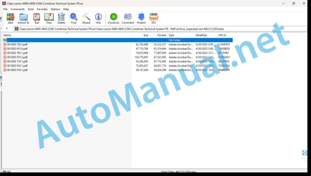
File List:
00 0300 726 2.pdf
00 0302 615 0.pdf
00 0302 783 1.pdf
00 0303 075 3.pdf
00 0303 119 1.pdf
00 0303 816 1.pdf
00 0305 019 1.pdf
00 0302 783 1.pdf:
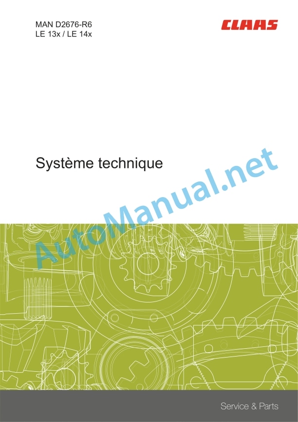
MAN D2676-R6LE 13x / LE 14x
Contents
Introduction
Safety tips
Safety instructions and dangers
Validity of the notice
Validity of the notice
Security
General instructions
Marking of warnings and dangers
Safety Routines
First aid measures
CCN explanation
CCN (CLAAS Component Number – CLAAS part number)
CCN (CLAAS Component Number – CLAAS part number)
01 Motor
0125 Injection system, fuel supply
System Description
Schematic structure of the Common Rail system
Schematic structure of the SCR dosing system
High pressure pump
High pressure pump CP3.4
ZME Unit of Measurement (Y332-MAN)
Pin assignment
High pressure accumulator (Rail)
Pressure limiter
Rail Pressure Sensor (B487-MAN, B514-MAN)
Connector allocation
Injector (Y341-MAN – Y346-MAN)
0135 Cooling system
Make-up tank coolant level sensor
Connector allocation
0155 Engine controls
EDC17 control unit (A435-MAN)
Pin allocation of the EDC17 control unit
Control unit connector A
Control unit connector B
Control unit connector C
Control unit connector D
Crankshaft Sensor (Incremental RPM Sensor) (B488-MAN)
Connector allocation
Connection diagram
Camshaft Sensor (Segmented RPM Sensor) (B489-MAN)
Connector allocation
Connection diagram
Oil Pressure Sensor (B104-MAN)
Sensor characteristic curve
Connector allocation
Fuel Pressure Sensor (B377-MAN)
Sensor characteristic curve
Connector allocation
PFM air mass measuring device
Connector allocation
Intake Pressure Sensor/Temperature Sensor (B623-MAN)
Connector allocation
Coolant Temperature Sensor (B124-MAN)
Connector allocation
Connection diagram
Charge Air Temperature Sensor (B123-MAN)
Connector allocation
Connection diagram
VTG compressor (turbocharger)
VTG Actuator Pin Allocation
VTG RPM Sensor Pin Allocation
0165 Exhaust gas aftertreatment
Post-treatment of exhaust gases
Graphical representation of the in-line cylinder engine with SCR
Suction air temperature sensor
Connector allocation
Exhaust Gas Thermocouples (A1191-MAN)
Connector allocation
EGR Servo Motor (M289-MAN)
Connector allocation
Lambda probe (B322-MAN)
Connector allocation
Power Module (A808-MAN)
Connector allocation
Dosing module (A1279-MAN)
Connector allocation
Tank Heater Valve (Y437-MAN)
Connector allocation
AdBlue® Combination Transmitter (A1192-MAN)
Connector allocation
NOx Sensor I (gross emission) (B1055-MAN)
Connector allocation
NOx II sensor (diagnostic) (B994-MAN)
Connector allocation
Differential pressure sensor for diesel particulate filter
Connector alloaion
Connection diagram
10 Electrical/electronic system
1080 Electrical connection plan
Electrical connection diagram of the EDC17 measuring device
1085 Network functions
CAN bus and power supply overview
90 Others
9090 Diagnosis
HD-OBD diagnostic socket (X200-MAN)
Error logging
CDS error display
FMI (Failure Mode Identification)
List of steps for checking the EDC17 control unit
1. Measurements on the EDC17 motor control device
Acceleration test
Description
Compression test
Description
Cylinder Disconnect Test
Description
Acceleration test
Description
Injector test
Description
Reset pressure relief valve
Description
Pressure limiter test
Description
SCR dosage quantity test
Description
Reset SCR system errors
Description
System test of the SCR dosing system
Description
Reset the incentive counter
Description
Fuel supply scheme
Quick Overview of D26 Engine Fuel
Troubleshooting the CAN connection
1. NOx I sensor (gross emission)
2. EGR adjustment unit
3. NOx II sensor (diagnostic)
4. Thermocouples
5. AdBlue® combined transmitter
Diagnostic program
Troubleshooting in the SCR dosing system
General overview
RPM plausibility/blocked pump
Leaking suction line
Return blocked
SPN 94- FMI 1: fuel supply pressure too high
SPN 94- FMI 2: fuel supply pressure too low
SPN 98 – FMI 1: engine oil level too high
SPN 98 – FMI 2: engine oil level too low
SPN 98 – FMI 3: implausible engine oil level
SPN 100 – FMI 1: engine oil pressure too high
SPN 100 – FMI 2: engine oil pressure too low
SPN 102 – FMI 1: charge air pressure before the engine (in the charge air tube) too high
SPN 102 – FMI 1: charge air pressure before the engine (in the charge air tube) too low
SPN 102 – FMI 3: Charge air pressure signal before the engin (n the charge air tube) is not plausible
SPN 102 – FMI 8: Charge air pressure signal before engine (in charge air tube) is invalid
SPN 105 – FMI 1: charge air temperature before cylinder intake (after EGR supply) too high
SPN 105 – FMI 2: charge air temperature before cylinder intake (after EGR supply) too low
SPN 105 – FMI 8: Invalid charge air temperature signal before cylinder intake (after EGR supply)
SPN 110 – FMI 1: coolant temperature too high
SPN 110 – FMI 2: coolant temperature too low
SPN 168 – FMI 1: battery voltage too high
SPN 168 – FMI 2: battery voltage too low
SPN 168 – FMI 5: battery voltage – short circuit to ground
SPN 168 – FMI 6: battery voltage short circuit
SPN 171 – FMI 1: ambient air temperature too high
SPN 171 – FMI 2: battery voltage too low
SPN 174 – FMI 1: fuel temperature too high
SPN 174 – FMI 3: implausible fuel temperature
SPN 609 – FMI 4: absence of signal at the CAN bus motor
SPN 609 – FMI 8: invalid signal at the CAN-bus motor
SPN 651 – FMI 7: short circuit in the current path – solenoid valve 1
SPN 651 – FMI 9: device error – solenoid valve 1
SPN 651 – FMI 10: interruption in the current path – solenoid valve 1
SPN 652 – FMI 7: short circuit in the current path – solenoid valve 5
SPN 652 – FMI 9: device error – solenoid valve 5
SPN 652 – FMI 10: interruption in the current path – solenoid valve 5
SPN 653 – FMI 7: short circuit in the current path – solenoid valve 3
SPN 653 – FMI 9: device error – solenoid valve 3
SPN 653 – FMI 10: interruption in the current path – solenoid valve 3
SPN 654 – FMI 7: short circuit in the current path – solenoid valve 6
SPN 654 – FMI 9: device error – solenoid valve 6
SPN 654 – FMI 10: interruption in the current path – solenoid valve 6
SPN 655 – FMI 7: short circuit in the current path – solenoid valve 2
SPN 655 – FMI 9: device error – solenoid valve 2
SPN 655 – FMI 10: interruption in the current path – solenoid valve 2
SPN 656 – FMI 7: short circuit in the current path – solenoid valve 4
SPN 656 – FMI 9: device error – solenoid valve 4
SPN 656 – FMI 10: interruption in the current path – solenoid valve 4
SPN 1079 – FMI 8: short circuit of sensor supply 6
SPN 1080 – FMI 8: short circuit of sensor supply 4
SPN 1131 – FMI 1: charge air temperature before the engine (in the charge air tube) too high
SPN 1131 – FMI 2: charge air temperature before the engine (in the charge air tube) too low
SPN 1131 – FMI 8: Charge air temperature signal before engine (in charge air tube) is invalid
SPN 1761 – FMI 3: urea filling level signal is not plausible
SPN 1761 – FMI 8: invalid urea filling level signal
SPN 3004 – FMI 4: EGR valve blocked
SPN 3005 – FMI 1: position of the exhaust gas recirculation (EGR) valve too high
SPN 3005 – FMI 2: position of the exhaust gas recirculation (EGR) valve too low
SPN 3009 – FMI 1: engine speed too high
SPN 3014 – FMI 3: signal from control devices – main relay implausible
SPN 3046 – FMI 3: implausible atmospheric pressure sensor signal
SPN 3046 – FMI 4: faulty atmospheric pressure sensor signal
SPN 3046 – FMI 5: atmospheric pressure sensor – short circuit to ground
SPN 3046 – FMI 6: atmospheric pressure sensor – short circuit to battery plus
SPN 3046 – FMI 11: false contact of the atmospheric pressure sensor
SPN 3060 – FMI 4: EGR valve – no signal
SPN 3060 – FMI 8: EGR valve – invalid signal
SPN 3076 – FMI 8: start lock – wrong code
SPN 3077 – FMI 3: start lock – code does not exist
SPN 3082 – FMI 1: oil pressure sensor signal too high
SPN 3082 – FMI 2: oil pressure sensor signal too low
SPN 3083 – FMI 1: Rail pressure sensor signal too high
SPN 3083 – FMI 2: rail pressure sensor signal too low
SPN 3083 – FMI 3: implausible rail pressure sensor signal
SPN 3087 – FMI 1: oil pressure sensor signal too high
SPN 3087 – FMI 3: implausible oil pressure sensor signal
SPN 3087 – FMI 4: Missing oil pressure sensor signal
SPN 3087 – FMI 5: oil pressure sensor – short circuit to ground
SPN 3087 – FMI 11: false contact of the oil pressure sensor
SPN 3087 – FMI 5: oil pressure sensor – interruption or short circuit to more
SPN 3088 – FMI 3: Implausible manifold pressure sensor signal
SPN 3088 – FMI 5: manifold pressure sensor – short circuit to ground
SPN 3088 – FMI 11: intake pressure sensor false contact
SPN 3088 – FMI 12: manifold pressure sensor – interruption or short circuit to more
SPN 3089 – FMI 3: Implausible charge air temperature sensor signal
SPN 3089 – FMI 5: charge air temperature sensor – short circuit to ground
SPN 3089 – FMI 6: manifold pressure sensor – short circuit to plus
SPN 3089 – FMI 10: charge air temperature sensor – interruption
SPN 3089 – FMI 11: false contact of the charge air temperature sensor
SPN 3089 – FMI 12: manifold pressure sensor – interruption or short circuit to more
SPN 3091 – FMI 3: Implausible coolant temperature sensor signal
SPN 3091 – FMI 4: Coolant temperature sensor signal missing
SPN 3091 – FMI 5: coolant temperature sensor – short circuit to ground
SPN 3091 – FMI 6: coolant temperature sensor – short circuit to plus
SPN 3091 – FMI 10: coolant temperature sensor – interruption
SPN 3091 – FMI 11: coolant air temperature sensor false contact
SPN 3099 – FMI 12: rail pressure sensor – interruption or short circuit to more
SPN 3099 – FMI 13: rail pressure sensor – interruption or short circuit to ground
SPN 3100 – FMI 3: implausible fuel pressure sensor signal
SPN 3100 – FMI 4: Fuel pressure sensor signal missing
SPN 3100 – FMI 11: false contact of the fuel pressure sensor
SPN 3100 – FMI 12: fuel pressure sensor – interruption or short circuit to more
SPN 3100 – FMI 13: fuel pressure sensor – interruption or short circuit to ground
SPN 3456 – FMI 2: urea filling level < 10%
SPN 3457 - FMI 2: low urea filling level
SPN 3752 - FMI 4: camshaft sensor signal missing
SPN 3752 - FMI 5: camshaft sensor - short circuit to ground
SPN 3752 - FMI 6: camshaft sensor - short circuit to plus
SPN 3753 - FMI 4: crankshaft sensor signal missing
SPN 3753 - FMI 5: crankshaft sensor - short circuit to ground
SPN 3753 - FMI 6: crankshaft sensor - short circuit to plus
SPN 3753 - FMI 8: crankshaft sensor - incorrect signal
SPN 3753 - FMI 10: crankshaft sensor - breakage
SPN 3775 - FMI 1: rail pressure too high
SPN 3775 - FMI 2: rail pressure too low
SPN 3776 - FMI 1: positive rail pressure regulation difference
SPN 3778 - FMI 1: rail pressure leak under thrust conditions
SPN 3780 - FMI 1: rail pressure leak at idle
SPN 3781 - FMI 1: pressure limiter open
SPN 3797 - FMI 5: heating of the Lambda probe - short circuit to ground
SPN 3797 - FMI 6: Lambda sensor heating - short circuit to plus
SPN 3797 - FMI 10: heating of the Lambda probe - breakage
SPN 3823 - FMI 3: misfire on several cylinders
SPN 3824 - FMI 3: misfire of cylinder 1
SPN 3825 - FMI 3: misfire of cylinder 5
SPN 3826 - FMI 3: misfire of cylinder 3
SPN 3827 - FMI 3: misfire of cylinder 6
SPN 3828 - FMI 3: misfire of cylinder 2
SPN 3829 - FMI 3: misfire of cylinder 4
SPN 3837 - FMI 1: Lambda sensor oxygen signal too high
SPN 3837 - FMI 2: Lambda sensor oxygen signal too low
SPN 3843 - FMI 3: Implausible coolant temperature sensor signal
SPN 3843 - FMI 8: Invalid coolant temperature
SPN 3845 - FMI 3: implausible ambient temperature
SPN 3847 - FMI 3: Implausible manifold pressure sensor/temperature sensor signal
SPN 3847 - FMI 4: Intake Pressure Sensor/Temperature Sensor Signal Missing
SPN 3847 - FMI 5: Intake Pressure Sensor/Temperature Sensor - Short to Ground
SPN 3847 - FMI 6: Intake Pressure Sensor/Temperature Sensor - Short to Plus
SPN 3847 - FMI 10: manifold pressure sensor/temperature sensor - rupture
SPN 3847 - FMI 11: intake pressure sensor/temperature sensor - false contact
SPN 3848 - FMI 3: ambient air temperature sensor signal implausible
SPN 3848 - FMI 5: ambient air temperature sensor - short circuit to ground
SPN 3848 - FMI 6: ambient air temperature sensor - short circuit to plus
SPN 3848 - FMI 10: ambient air temperature sensor - interruption
SPN 3848 - FMI 11: false contact of the ambient air temperature sensor
SPN 3855 - FMI 5: Lambda probe sensor cables - short to ground
SPN 3855 - FMI 6: Lambda probe sensor cables - short circuit to plus
SPN 3856 - FMI 1: Lambda probe calibration too high
SPN 3856 - FMI 2: Lambda probe calibration too low
SPN 3857 - FMI 3: implausible values of the Lambda probe evaluation unit
SPN 3858 - FMI 1: Lambda probe temperature too high
SPN 3858 - FMI 2: Lambda probe temperature too low
SPN 3859 - FMI 1: Lambda probe temperature calibration too high
SPN 3859 - FMI 2: Lambda probe temperature calibration is too low
SPN 3919 - FMI 7: NOx sensor after post-treatment of exhaust gasesateror status (short circuit)
SPN 3919 - FMI 10: NOx sensor after exhaust gas aftertreatment: heater error status (interruption)
SPN 3920 - FMI 3: NOx sensor after post-treatment of exhaust gases: NOx concentration error status
SPN 3920 - FMI 7: NOx sensor after exhaust gas post-treatment: NOx concentration error status (short circuit)
SPN 3920 - FMI 10: NOx sensor after exhaust gas aftertreatment: NOx concentration error status (interruption)
SPN 3921 - FMI 1: NOx sensor after exhaust gas post-treatment: Lambda signal error status
SPN 3921 - FMI 2: NOx sensor after exhaust gas post-treatment: Lambda signal error status
SPN 3921 - FMI 3: NOx sensor after exhaust gas post-treatment: Lambda signal error status
SPN 3926 - FMI 11: false contact of the rail pressure sensor
SPN 3927 - FMI 9: Lambda probe not integrated into the exhaust pipe
SPN 3929 - FMI 1: EGR Lambda regulation deviation
SPN 3929 - FMI 2: EGR Lambda regulation deviation
SPN 3930 - FMI 1: EGR Lambda regulation deviation
SPN 3938 - FMI 1: Lambda probe not adaptable
SPN 3938 - FMI 2: Lambda probe not adaptable
SPN 3938 - FMI 3: Lambda probe not adaptable
SPN 3938 - FMI 8: Lambda probe not adaptable
SPN 3972 - FMI 1: NOx value too high
SPN 3972 - FMI 2: NOx value too low
SPN 3972 - FMI 2: NOx value too low
SPN 4039 - FMI 5: actuator group 0 supply voltage short circuit
SPN 4039 - FMI 6: actuator group 0 supply voltage short circuit
SPN 4040 - FMI 5: actuator group 1 supply voltage short circuit
SPN 4040 - FMI 6: actuator group 1 supply voltage short circuit
SPN 4041 - FMI 5: Actuator group 2 supply voltage short circuit
SPN 4041 - FMI 6: actuator group 2 supply voltage short circuit
SPN 4070 - FMI 8: internal communication error of the EDC control unit (with CY146 module)
SPN 4071 - FMI 8: internal communication error of the EDC control unit (with CY146 module)
SPN 4072 - FMI 8: internal communication error of the EDC control unit (with CY146 module)
SPN 4073 - FMI 8: internal communication error of the EDC control unit (with CY317 module)
SPN 4074 - FMI 8: internal communication error of the EDC control unit (with CY320 module)
SPN 4400 - FMI 9: urea system defrost failure (device error)
SPN 4400 - FMI 9: failure to defrost the AdBlue® system (hardware failure)
SPN 4401 - FMI 8: urea system: dosage
SPN 4400 - FMI 9: urea system: dosage
SPN 4409 - FMI 9: sensor 5 power supply: short circuit to ground or more
SPN 4439 - FMI 1: heating of the urea tank: temperature too high
SPN 4439 - FMI 5: urea tank heating: final stage error
SPN 4439 - FMI 6: urea tank heating: final stage error
SPN 4439 - FMI 10: urea tank heating: final stage error
SPN 4447 - FMI 8: sensor supply 1: short circuit
SPN 4448 - FMI 8: sensor supply 2: short circuit
SPN 4449 - FMI 8: sensor supply 3: short circuit
SPN 4469 - FMI 1: exceeding the NOx threshold
SPN 6140 - FMI 5: airless dosing system (pressure sensor)- shortcircuit after ground
SPN 6140 - FMI 6: Airless dosing system (pressure sensor) - short circuit (UBat)
SPN 6140 - FMI 11: Airless dosing system (pressure sensor) - (false contact)
SPN 6142 - FMI 5: Airless dosing system (temperature sensor) - short circuit after ground
SPN 6142 - FMI 6: Airless dosing system (temperature sensor) - short circuit after UBat
SPN 6142 - FMI 11: Airless dosing system (temperature sensor) - false contact
SPN 6143 - FMI 6: Urea dosing valve - short circuit after UBat
SPN 6143 - FMI 7: Urea dosing valve - short circuit
SPN 6143 - FMI 12: Urea dosing valve - short circuit or interruption to more
SPN 6143 - FMI 13: Urea dosing valve - short circuit to ground or interruption
SPN 6151 - FMI 1: Final stage of PTC heating
SPN 6151 - FMI 2: PTC final stage
SPN 6151 - FMI 5: PTC final stage - short circuit (ground)
SPN 6151 - FMI 6: PTC final stage - short circuit (UBat)
SPN 6151 - FMI 10: PTC final stage - interruption (Open Load)
SPN 6161 - FMI 1: SCR pump blocked
SPN 6161 - FMI 2: correlation of pressure and speed of the SCR pump
SPN 6163 - FMI 1: Correlation of pressure and speed of the SCR pump on the service routine
SPN 6163 - FMI 2: Correlation of pressure and speed of the SCR pump on the service routine
SPN 6163 - FMI 3: Correlation of pressure and speed of the SCR pump on the service routine
SPN 6164 - FMI 9: Hardware failure of the dosing unit
SPN 6165 - FMI 3: Correlation of pressure and speed of the SCR pump
SPN 6166 - FMI 1: SCR pump speed
SPN 6166 - FMI 3: SCR pump speed
SPN 6170 - FMI 9: SCR pump hardware failure
SPN 6171 - FMI 1: Replace the SCR pump filter
SPN 6172 - FMI 1: The SCR pump filter is full
SPN 6197 - FMI 5: airless dosing system (speed feedback message)
SPN 6197 - FMI 6: airless dosing system (speed feedback message)
SPN 6207 - FMI 1: Power module final stage
SPN 6207 - FMI 5: Final stage of the urea dosing pump - short circuit after ground
SPN 6207 - FMI 6: Final stage of the urea dosing pump - short circuit after UBat
SPN 6207 - FMI 10: Final stage of the urea dosing pump - interruption
SPN 6212 - FMI 9: failure to defrost the AdBlue® system - hardware failure
92 Diagnosis
9220 Diesel Engine Error Codes (J1939)
Diesel Engine SPN List
Error codes
SPN list SCR dosing system
Error codes
Location of parts
Electrical system
A435-MAN Engine management module
Component
Mounting points
High pressure pump
Component
Mount point
Unit of measurement (ZME)
Component
Mount point
High pressure accumulator (Rail)
Component
Mount point
Pressure limiter
Component
Mount point
Rail Pressure Sensor (B487-MAN)
Component
Mount point
Injectors (Y34x-MAN)
Component
Mount point
B488-MAN Crankshaft sensor (incremental speed sensor)
Component
Mount point
Camshaft Sensor (B489-MAN)
Component
Mout point
Oil Pressure Sensor (B104-MAN)
Component
Mount point
Fuel Pressure Sensor (B377-MAN)
Component
Mount point
PFM air mass measuring device
Component
Mount point
Intake Pressure Sensor/Temperature Sensor (B623-MAN)
Component
Mount point
Charge Air Temperature Sensor (B123-MAN)
Component
Mount point
Coolant Temperature Sensor (B124-MAN)
Component
Mount point
VTG turbocharger
Component
Mount point
Suction air temperature sensor
Component
Mount point
Differential pressure sensor for diesel particulate filter
Component
Mount point
Exhaust Gas Thermocouples (A1191-MAN)
Component
Mount point
EGR Servo Motor (M289-MAN)
Component
Mount point
Lambda probe (B322-MAN)
Component
Mount point
Power Module (A808-MAN)
Component
Mount point
Dosing module (A1279-MAN)
Component
Mount point
Tank Heater Valve (Y437-MAN)
Component
Mount point
AdBlue® Combination Transmitter (A1192-MAN)
Component
Mount point
NOx I sensor (raw emission - B1055-MAN)
Component
Mount point
NOx II sensor (diagnostic - B994-MAN)
Component
Mount point
John Deere Repair Technical Manual PDF
John Deere Repair Technical Manual PDF
John Deere Repair Technical Manual PDF
John Deere Repair Technical Manual PDF
John Deere 16, 18, 20 and 24HP Onan Engines Component Technical Manual CTM2 (19APR90)
John Deere Repair Technical Manual PDF
John Deere Repair Technical Manual PDF
John Deere Parts Catalog PDF
John Deere Tractors 7500 Parts Catalog CPCQ26568 30 Jan 02 Portuguese
John Deere Repair Technical Manual PDF
John Deere Diesel Engines PowerTech 4.5L and 6.8L – Motor Base Technical Manual 07MAY08 Portuguese
John Deere Parts Catalog PDF
John Deere Tractors 6300, 6500, and 6600 Parts Catalog CQ26564 (29SET05) Portuguese
John Deere Repair Technical Manual PDF
John Deere POWERTECH E 4.5 and 6.8 L Diesel Engines TECHNICAL MANUAL 25JAN08

