Claas Lexion 760-740 (C75) Combines Technical System FR
$150.00
- Model: Lexion 760-740 (C75) Combines
- Type Of Manual: Technical System
- Language: FR
- Format: PDF(s)
- Size: 295 MB
File List:
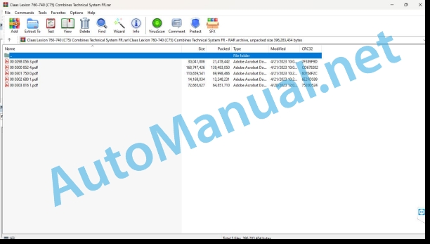
00 0298 056 3.pdf
00 0300 852 4.pdf
00 0301 750 0.pdf
00 0302 680 1.pdf
00 0303 816 1.pdf
00 0301 750 0.pdf:
PERKINS 2206F – E13 TA
Contents
CCN explanation
CCN (CLAAS Component Number)
Electrical standard
Overview
CCN (CLAAS Component Number)
Introduction
Validity of the notice
Validity of the notice
Safety tips
Safety instructions and dangers
General informations
Important !
Warning pictogram
Signal word
Instructions to avoid accidents and personal injury
Inspection, adjustment and repair work
Engine operation
Suspended loads
Work on tubular pipes and flexible pipes
Work on the Common Rail system
Work on the electrical system
Work on the hydraulic system
Electric welding
Paint work
Works with urea solution
Notes to avoid damage and premature wear
Limits of liability
Shutdown and storage
Instructions to avoid damage to health and the environment
Preventive measures to protect against damage to health and the environment
Disposal of operating consumables, secondary consumables
Information regarding work on the diesel engine
Protection against accidents
Cleanliness
Installation Instructions
Engine overhaul
Commissioning after engine overhaul
First aid measures
Directory of abbreviations
Example: Pulse Width Modulation (PWM)
01 Motor
0102 Complete set
Complete components
Engine components – left side
Engine components – exhaust gas turbocharger side
Perkins 2206F-E13TA Diesel Engine Nameplate
Clean Emissions Module (CEM) nameplate
Urea pump nameplate
Technical characteristics of Perkins 2206F-E13TA diesel engine
Around the Perkins 2206F-E13TA diesel engine
General informations
Introduction
0110 Motor housing
Basic engine
Crankcase cylinder
Description of operation
Camshaft
0120 Cylinder head – Valves – Distribution
Cylinder head – valves – wheel drive
Valve System Components
Description of operation
Gear train (front) – Distribution
Description of operation
Crankcase breather
0125 Injection system, fuel supply
Cleanliness of fuel system components
Engine cleanliness
Working environment
Tool that must be used for cleanliness during fuel injection operations: warranty condition.
New components
Injection system / fuel system
Fuel system (example figure)
Description of operation
Low pressure fuel system
Description of operation
Unit injector mechanism
Pump injector
0130 Lubrication system
Lubricating oil system
Lubrication system diagram
View of the right side of the engine
Description of operation
Oil flow through the lubrication system
Description of operation
Interior of the cylinder block
0135 Cooling system
Cooling system
Coolant flow
Description of operation
View of the right side of the engine
Air compressor coolant (if installed)
0140 Exhaust device
Exhaust line
Air intake and exhaust system
Description of operation
Air intake and exhaust system
Turbocharger
Balance Valve Solenoid Circuit
Balancing valve solenoid
Balancing valve solenoid in closed position
Balance valve solenoid in open position
0155 Engine controls
PERKINS 2206F-13TA (LEXION TYPE C75) diesel engine monitoring
Measurement value table
Description of operation
PERKINS 2206F-13TA Diesel Engine Warning Lights
Overview of Problems Related to Low Urea
Exhaust aftertreatment defects and corrective actions
Overview of problems in exhaust gas recirculation*
System operation, diesel engine monitoring
Electronic management system components
Description of operation
Block diagram of exhaust gas aftertreatment system
Description of operation
0165 Exhaust gas aftertreatment
Empty and clean the urea solution tank
Tank, electronics and pump assembly (PETU “Pump Electronic and Tank Unit”)
Description of the function
DEF pump
Emission Control Module (EMC)
Illustration – Emission Control Module (EMC)
Description of operation
Sectional view of the interior of the FAP
SCR cartridge.
Regeneration of the FAP
Turbocharger Compressor Bypass Valve (TCBV).
Description of operation
DEF Dosing Control System
Illustration of the FED system
Illustration of the pumps, electronics and tank assembly (PETU)
Description of operation
DEF pump
FED tank riser
Coolant bypass valve
DEF injector
Nitrogen oxide (NOx) sensors
Heated DEF System Pipes
0197 Test – Measurement – Adjustment
Fuel system – inspect
Air in fuel – test
Testing fir bubbles in fuel
Electr unit injector – adjust
Injector mechanism
Electronic pump injector – test
Injector adaptation file – install
Diagnostic Error Codes for Bad Injector Data
Figure of injector numbers
Installing the injector adaptation file
Identifying the top dead center of piston no. 1
Timing hole
Fuel quality – test
Turbocharger – inspect
Checking the turbine wheel and turbine housing
Exhaust temperature – test
Aftercooler – test
Exhaust gas cooler (NRS) – clean
Steam cleaner jet direction
Exhaust gas cooler (NRS) – test
Underwater air leak test procedure.
Waterproof vent cap
Crankcase gas pressure (blow-by) – test
Compression – test
Engine valve clearance – inspect/adjust
Valve Clearance Adjustment
Engine oil pressure – test
Measuring engine oil pressure
Reasons for low engine oil pressure
Reason for high engine oil pressure
Engine oil pump – inspect
Excessive bearing wear – inspect
Excessive engine oil consumption – inspect
Increased engine oil temperature – inspect
Cooling system – check (overheating)
Cooling system – inspect
Cooling system – test
Boiling point of water
Check the filler cap
Typical filler cap diagram
Check the radiator and cooling system for leaks
Water thermometer test
Water collector
Water temperature regulator – test
Water pump – test
Vibration damper – check
Viscous vibration damper
Control the urea solution
Preparing for work
Special tool
Check the urea solution (purity)
Check the urea solution (density)
Exhaust gas aftertreatment – RCS dosing test system
FED injector screwed onto the measuring vessel
Example of a test kit for the DEF injector test procedure
DEF Injector Spray Test
Description of the function
Exhaust gas aftertreatment identification module – test
Exhaust Aftertreatment Identification Module Diagnostic Error Codes
Type EMC nameplate
Data binding – test
Diagnostic Error Codes for CAN Data Connection Circuit
The following basic information is important for this measurement
CAN network diagram
Data connection configuration status – inspect
Diagnostic codes for data connection configuration status – inspect
DEF Control Module Power Supply – Test (A032)
Diagnostic Codes for FED Control Module (A032), Power Supply
DCU power supply circuit (A032)
DEF line heater – test
Diagnostic Error Codes for DEF Line Heater
Schematic representation of the FED heating circuit
Overview of the PETU set
Overview of PETU relays
DEF pump motor – test
Diagnostic Error Codes for DEF Pump
DEF pump motor diagram
DEF pump, pressure sensor – inspect
Diagnostic Error Codes
Schematic representation of the FED pressure sensor and contact pins
DEF pump, sensor feed – inspect
Diagnostic Error Codes
Schematic representation of the DEF pump sensor power supply and contact pins
DEF pump – replace
Diagnostic Error Codes
DEF return valve – inspect
Diagnostic Error Codes
Schematic representation of the DEF pump return valve circuit
DEF tank sensor – inspect
Diagnostic Error Codes
Schematic representation of DEF tank sensor circuit
Power supply – inspect
Diagnostic Codes
Power supply diagram – test
Exhaust balancing valve – test
Typical example of tools needed
Connection points to check (1)
Balancing valve
Balancing valve test diagram
Hose from mixer to exhaust balance valve solenoid (7)
Example of necessary tools
Connection for line to exhaust balancing valve (11)
Exhaust Balance Valve Chamber Cover (12)
Injector solenoids – test
Diagnostic Error Codes for Injector Magnetic Coil Circuit
Basic information
Diagnostic Tests on the Electronic Service Tool (CDS)
Schematic representation of the circuit for the injector magnetic coils
NOx Reduction System (NRS) – test
Diagnostic Error Codes for NRS (EGR)
Inspection points for the left side of the engine
Inspection points for the right side of the engine
NRS valve
NRS valve body
NRS valve sensors
NRS sensor installation locations
NOx sensor – inspect
NOx Sensor Diagnostic Error Codes
SCR catalyst inlet temperature sensor – test
Diagnostic Error Codes
FAP diagram and SCR catalyst
SCR Catalyst Inlet Temperature Probe (B351)
Sensor calibration required – inspect
Diagnostic Error Codes for Sensor Calibration
Sensor (data connection type) – inspect
Diagnostic Error Codes for Data Connection Sensors
CAN network diagram
Sensor signal (analog, active) – test
Diagnostic Error Codes for Analog Active Sensors
Schematic representation of pressure sensors (analog, active)
Schematic representation of sensors (analog, active)
Sensor signal (analog, passive) – test
Diagnostic Error Codes for Analog Passive Sensors
Terminal locations on the passive analog sensor connector
Schematic representation of sensors (analog, passive)
Sensor power supply – test
Sensor Power Diagnostic Error Codes
System operation
Sensor connector
Simplified diagram of the ECM circuit.
Solenoid valve – test
Diagnostic Error Codes for Solenoid Valves (Table 249)
Table (250) Problem/Solution
Solenoid valve diagram (A015) – (A179)
DCU solenoid valve diagram (A032)
RPM/ignition point – test
Diagnostic Codes for Engine RPM/Ignition Point Sensors
Description of operation
Graphical representation of engine speed / ignition point sensors
Crankshaft speed/position sensor
Camshaft speed/position sensor
Terminal Locations on Engine Speed/Ignition Point Sensor Connector
Distribution – calibrate
Diagnostic Error Codes
Description of operation
Detailed diagram of the installation of the pulse transmitter
Illustration of distribution calibration
Turbocharger compressor bypass – test
Diagnostic Error Codes for Turbocharger Compressor Bypass Valve (TCBV)
Turbocharger Compressor Bypass Valve (TCBV) Diagram
Turbocharger Compressor Bypass Valve (TCBV).
Turbocharger compressor bypass valve – replace
Electrical connections – inspect
Connector illustration. Detail A
Schematic representation of the assembly of a connector (typical example)
Joint of a three-pin connector
ECM connector gasket
Receptacle lock wedge
Pin Hold Test Schematic
Checking the hexagon socket screws on the connectors
Hex socket screw for 120 pin ECM connector
Hex socket screw for 70 pin ECM connector
Hexagon socket screw for 40-pin customer connector and 70-pin customer connector
ECM test mode
Replacement of engine, engine ECM, EAM, DCU, DPF, CEM
Additional procedures when replacing the engine, engine ECM, exhaust aftertreatment ECM, DCU or CEM
Configuration settings
Codes related to configuration settings
Description of operation
ECM software – install
Codes related to configuration settings
Description of operation
0198 Fault / Remedy
Emission Control Module High Oxygen Level
Recommended actions
Diagnostic Error Codes
Presence of fuel in the coolant
Introduction
Possible causes
Recommended actions
Presence of oil in the coolant
Introduction
Possible causes
Recommended actions
High coolant temperature
Introduction
Diagnostic error code for high coolant temperature
Possible causes
Recommended actions
Low coolant temperature
Introduction
Diagnostic error code for low coolant temperature
Possible causes
Test steps for fixing defects
Noisy cylinder
Possible causes
Recommended actions
FED concentration is bad
Recommended actions
Diagnostic Error Codes: For DEF concentration is bad
DEF Control Module High Temperature (DCU A032)
Dosing Control Unit, DCU (A032)
Recommended actions
Diagnostic Error Code for DEF Control Module Temperature is High
No purge of the FED
Recommended actions
Diagnostic error code for DEF is not drained
Lack of reaction from the FED module
Recommended actions
Diagnostic error code for DEF module not responding
Lack of DEF pressure reaction
Diagnostic error code for DEF pressure not responding
DEF pump figure
High DEF Pressure
Diagnostic error code for DEF pressure is high.
DEF pump figure
Low DEF Pressure
Diagnostic error code for DEF pressure is low.
DEF pump figure
DEF Pump Filters
DEF Tank Filters
Low DEF tank level
Degraded Mode for Diesel Exhaust Fluid (DEF) Tank Level
Diagnostic error code for DEF tank fill level is low
Figure of the DEF tank
High temperature in DEF tank
Diagnostic error code for temperature in DEF tank is high
Urea Heater Coolant Valve (Y488)
Low temperature in DEF tank
Diagnostic error code for temperature in DEF tank is low.
Urea Heater Coolant Valve (Y488)
Frequent desulfation
Diagnostic error codes.
Exhaust mixer.
Excessive amount of soot collected in the diesel particulate filter
Possible causes
Diagnostic error code for excessively high soot load
Fault correction measures
High ash load from diesel particulate filter
High pressure at the inlet of the diesel particulate filter
Possible causes
Diagnostic Error Codes
Low pressure at the diesel particulate filter inlet
Possible causes
Diagnostic Error Codes
No regeneration of the diesel particulate filter
Possible causes
Diagnostic Error Codes
High diesel particulate filter temperature
Possible causes
Diagnostic Error Codes for High Diesel Particulate Filter Temperature
Low diesel particulate filter temperature
Possible causes
Diagnostic error codes for diesel particulate filter temperature is low.
DPF inlet temperature sensor and wiring (1)
The engine is started but does not start
Recommended actions
No engine cranking
Recommended actions
Premature engine wear
Possible causes
Recommended actions
Mechanical engine noises (knocking)
Possible causes
Recommended actions
Misfires, rough operation or unstable engine speed
Possible causes
Recommended actions
Engine overspeed
Diagnostic Error Codes for Engine Overspeed
Possible causes
Recommended actions
Engine Stop Event
Diagnostic error code for engine shutdown
Probable cause of a code 6588-31
Recommended actions
Intermittent engine shutdowns
Possible causes
Recommended actions
Engine stalling at low speed
Possible causes
Recommended actions
Maximum engine speed not reached
Possible causes
Recommended actions
Excessive engine vibration
Possible causes
Recommended actions
Excessive black smoke in the exhaust
Possible causes
Manifest failure of a DPF
Excessive white smoke in the exhaust
Possible causes
Recommended actions
Presence of coolant in the exhaust line
Possible causes
Recommended actions
Presence of oil in the exhaust line
Possible causes
Recommended actions
High exhaust gas temperature
Possible causes
Recommended actions
Excessive fuel consumption
Possible causes
Recommended actions
High fuel pressure
Possible causes
Diagnostic Error Codes
Recommended actions
Fuel Lines
Fuel return line
Fuel Return Pressure Regulator (5)
Typical transfer pump. Pressure limiter (6)
Low fuel pressure
Possible causes
Diagnostic Error Codes
Recommended actions
Secondary and tertiary fuel filter
High fuel temperature
Possible causes
Diagnostic error code for fuel temperature is high
Recommended actions
Fuel Lines
Fuel return line
Fuel Return Pressure Regulator (5)
Low air pressure in intake manifold
Diagnostic Error Code List for Low Intake Manifold Pressure
Recommended actions
Typical inspection points
High air temperature in intake manifold
Diagnostic error code for air temperature in vacuum elbow is high.
Recommended actions
Inspection point, air-to-air aftercooler (ATAAC)
Low NOx conversion rate
Diagnostic error code for low NOx conversion rate
Recommended actions
Exhaust mixer
High NRS exhaust gas temperature
Recommended actions
Diagnostic Error Code for NRS Exhaust Gas Temperature is High
NRS (EGR) system components
NRS radiator
Typical view of the right side of the engine
Excessive oil consumption
Possible causes
Recommended actions
Presence of coolant in the oil
Possible causes
Recommended actions
Presence of fuel in the oil
Measure fuel dilution
Possible causes
Recommended actions
Low oil pressure
Diagnostic Codes for Low Engine Oil Pressure
Possible causes
Recommended actions
High oil temperature
Diagnostic Codes for High Oil Temperature
Possible causes
Recommended actions
Intermittently low power or intermittent loss of power
Possible causes
Recommended actions
Excessive sulphation of the SCR catalyst
Recommended actions
Diagnostic error code for excessive SCR catalyst sulfation
SCR warning system problem
User-level induction
Diagnostic Error Codes for RCS Warning System Problems
Excessive valve clearance
Possible causes
Recommended actions
Valve rotator or free spring lock
10 Electrical/electronic system
1012 Modules – Sensors
Module A015 – PERKINS 2206F-E13TA
Engine ECM A015
Module A015 – Engine Management Module (ECM)
Exhaust aftertreatment module (EAM) A179 – PERKINS 2206F-E13TA
SCM Exhaust Aftertreatment Module (EAM)
Module A179 – Exhaust aftertreatment module (EAM)
Module overview – PERKINS 2206F-E13TA
Engine connectors (ECM) A015
Connectors for Exhaust Aftertreatment (EAM) ECM Module (A179)
Diesel Exhaust Fluid Controller (DCU)
Sensors / actors – PERKINS 2206F – E13TA
Overview of the engine electrical system
Designations
Overview of electrical exhaust gas aftertreatment system
Designations
Sensor Locations for Engine
Sensor locations on left side of engine
Typical example of close-up views of sensor locations on the left side of the engine
Sensor locations on right side of engine
Typical example of close-up views of sensor locations on the right side of the engine
Sensor locations for the emissions control module
Sensor locations (view A – F)
View A of sensor locations
View B of sensor locations
View C of sensor locations
View D of sensor locations
View E of sensor locations
View F of sensor locations
Emission Control Module (EMC) Control Panel
Turbocharger Compressor Bypass Valve
DEF Dosing Unit (Top)
DEF dosing unit (right side)
DEF dosing unit (left side)
DEF Dosing Unit (Injector)
92 Diagnosis
9220 Diesel Engine Error Codes (J1939)
FMI (Failure Mode Indicator) error code
FMI (Failure Mode Indicator) error code “PERKINS”
FMI 00 (signal too large)
FMI 01 (signal too small)
IMF 02 (signal not plausible)
FMI 03 (voltage too high)
FMI 04 (voltage too low)
FMI 05 (current too low)
FMI 06 (current too high)
FMI 07 (mechanical error)
FMI 08 (wrong frequency signal)
FMI 09 (communication error)
FMI 10 (signal modification too fast)
FMI 11 (multiple r)
FMI 12 (ECU faulty)
I 13 (signal outside calibration range)
FMI 16 (parameter missing)
FMI 17 (ECU not responding)
FMI 18 (voltage supply error)
FMI 19 (software conditions not met)
Error codes
Diesel Engine Error Codes – J 1939 / PERKINS / 2206F – E13TA
9295 Measuring devices
Connecting the CDS Diagnostic Service Tool
Home screen after communicating with the CDS tool
CDS Features
Overview of modules
Engine management
Connecting the CDS Diagnostic Service Tool
Module diagnostics (Module diagnostics)
Engine testing
GENERAL 1: Location of motor tests
GENERAL 2: Menu selection (motor tests)
Testing injector solenoids (0125)
Test description
EGR system test (0140)
Test description
Turbocharger Compressor Bypass Valve Test (0140)
Test description
Cylinder cut-off test (0155)
Test description
Module output tests (0155)
Adjustment of module and valve outputs
Overview of Exhaust Aftertreatment System Testing (0165)
Test descriptions
Location of parts
Electrical system
A Terminal / modules
B Sensors
H System Signals / Indicators
M Motor (electric)
R Potentiometer / Resistance
Y Solenoid Coils
00 0302 680 1.pdf:
LEXION 760LEXION 750LEXION 740
Contents
Validity of the notice
Validity of the notice
General safety instructions
To be respected imperatively
Marking of warnings and dangers
Security
01 Motor
0165 Exhaust gas aftertreatment
Parts supplied in repair kit 00 2597 549 0
Installing the repair kit 00 2597 549 0
Parts supplied in repair kit 00 2597 545 0
Installing the repair kit 00 2597 545 0
Parts supplied in repair kit 00 2597 565 0
Installing the repair kit 00 2597 565 0
Parts supplied in repair kit 00 2597 562 0
Installing the repair kit 00 2597 562 0
John Deere Repair Technical Manual PDF
John Deere Repair Technical Manual PDF
John Deere Parts Catalog PDF
John Deere Tractors 6300, 6500, and 6600 Parts Catalog CQ26564 (29SET05) Portuguese
John Deere Repair Technical Manual PDF
John Deere Repair Technical Manual PDF
John Deere Repair Technical Manual PDF
John Deere Repair Technical Manual PDF
John Deere Repair Technical Manual PDF
John Deere Parts Catalog PDF
John Deere Tractors 7500 Parts Catalog CPCQ26568 30 Jan 02 Portuguese

