Claas Lexion 770 (C59) Combines Operator Manual FR
$50.00
- Model: Lexion 770 (C59) Combines
- Type Of Manual: Operator Manual
- Language: FR
- Format: PDF(s)
- Size: 79.8 MB
File List:
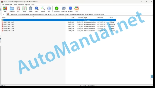
00 0291 090 4.pdf
00 0291 230 1.pdf
00 0291 818 4.pdf
00 0292 676 0.pdf
00 0292 792 0.pdf
00 0291 230 1.pdf:
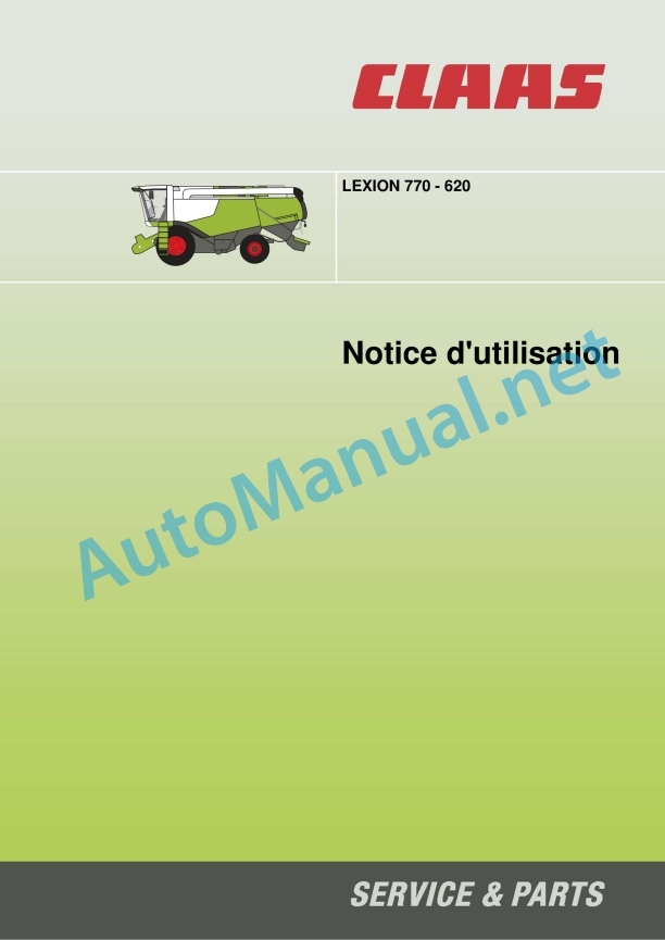
LEXION 770 – 620
Contents
1 Introduction
1.1 General information
1.1.1 Validity of the notice
2 Overview of adjustment elements
2.1 Cabin / Driving position
2.1.1 Multifunction handle
00 0291 818 4.pdf:
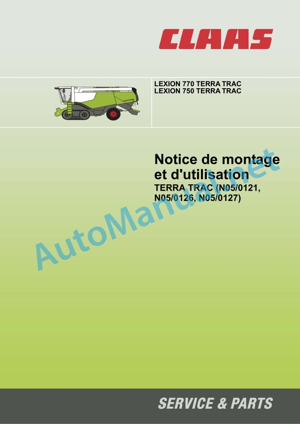
LEXION 770 TERRA TRAC
LEXION 750 TERRA TRAC
Contents
1 Introduction
1.1 General information
1.1.1 Use of the instructions
1.1.2 Validity of the notice
1.2 Nameplates and identification number
1.2.1 Technical characteristics
1.2.2 Spare parts and technical questions
1.2.3 TERRA TRAC nameplate
2 Security
2.1 General information
2.1.1 Important
2.1.2 Use in accordance with the provisions
2.2 Safety tips
2.2.1 Marking of warnings and dangers
2.3 Warning pictograms
2.3.1 General remarks relating to warning pictograms
2.3.2 Hydraulic system
3 Technical characteristics
3.1 LEXION 770 / 750 TERRA TRAC – Type C59 / C55
3.1.1 Machine equipment for technical characteristics
3.1.2 Undercarriage
3.1.3 Undercarriage track width
3.1.4 Brakes
3.1.5 Grain recovery – Dimensions
3.1.6 Dimensions of attached parts / machine (body)
4 pieces supplied
4.1 TERRA TRAC
4.1.1 Separate supply
4.1.2 Filling hose for tensioning TERRA TRAC treads
5 Assembly
5.1 TERRA TRAC
5.1.1 Switching off the machine
5.1.2 Check the parts provided
5.1.3 Install TERRA TRAC (1)
Special tool
Special tool
Calibrate TERRA TRAC with CDS
Calibrate TERRA TRAC with CEBIS
6 Before first commissioning
6.1 General information
6.1.1 General safety instructions
6.1.2 Checklist for initial commissioning
6.2 Assembly parts / Bodywork
6.2.1 Access ladder (LEXION 750 TERRA TRAC Australia)
6.2.2 Access ladder (LEXION 770 / 760 / 670 TERRA TRAC)
6.2.3 Access ladder (LEXION 750 TERRA TRAC)
6.2.4 Install the access ladder (LEXION 750 TERRA TRAC Australia)
6.2.5 Pre-assemble the access ladder (LEXION 770 / 760 / 750 / 670 TERRA TRAC)
6.2.6 Install the access ladder (LEXION 770 / 760 / 750 / 670 TERRA TRAC)
6.3 Chassis
6.3.1 Break-in of TERRA TRAC treads
6.3.2 Align the TERRA TRAC treads
7 Before each commissioning
7.1 General information
7.1.1 General safety instructions
7.1.2 Commissioning checklist
8 Road driving and transport
8.1 Assembly parts / Bodywork
8.1.1 Fold down the steps of the access ladder
8.1.2 Rotate the access ladder
8.1.3 Access ladder when traveling on slopes
9.1 Chassis
9.1.1 Checking the tension of the TERRA TRAC treads
10 Maintenance
10.1 General information
10.1.1 General safety instructions
10.2 General maintenance instructions
10.2.1 Fixing material
10.2.2 Maintenance work after harvest
10.2.3 Tightening torque for metric adjustment thread
10.2.4 Tightening torques for fine metric threads
10.2.5 Tightening torques for hydraulic couplings with cutting ring DIN 3861
10.2.6 Tightening torques for hydraulic connections and air conditioning connections with bicone ring and O-ring DIN 3865
10.3 Maintenance tables
10.3.1 TERRA TRAC bearing mechanism maintenance table
10.4 Lubricant tables
10.4.1 Lubricants
10.5 Lubrication plan
10.5.1 Lubrication points – 100 h left
10.5.2 Lubrication points – 100 h on the right
10.5.3 Lubrication points – 500 h left
10.5.4 Lubrication points – 500 h on the right
10.6 Chassis
10.6.1 Break-in of TERRA TRAC treads
10.6.2 Align the TERRA TRAC treads
10.6.3 Adjusting the tension of the TERRA TRAC treads
10.6.4 Checking the oil level of the drive wheel transmission
10.6.5 Draining the drive wheel transmission
10.6.6 Filling the drive wheel transmission
10.6.7 Checking the front steering wheel hub oil level
10.6.8 Draining the front steering wheel hub
10.6.9 Filling the front steering wheel hub
10.6.10 Checking the oil level of the central support wheel hubs
10.6.11 Draining the central support wheel hubs
10.6.12 Filling the hubs of the central support wheels
10.6.13 Checking the gearbox oil level
10.6.14 Draining the gearbox
10.6.15 Filling the gearbox
10.6.16 TERRA TRAC Tread Inspection
10.7 Hydraulics
10.7.1 Releasing the pressure of the hydraulic tread tension cylinder
10.7.2 Releasing the pressure of the hydraulic cylinder responsible for the suspension
00 0292 676 0.pdf:
LEXION 770 – 620TUCANO 470 – 320
Contents
1 About this user manual
1.1 General information
1.1.1 Validity of the notice
1.1.2 Symbols and instructions
2 Controls and displays
2.1 Cabin / Driving position
2.1.1 CEBIS control panel
2.2 CEBIS display
2.2.1 CEBIS general advice
2.2.2 Overview of the displacement indicator
2.2.3 Overview of the displacement indicator
2.2.4 Overview of the harvest indicator
2.2.5 CRUISE PILOT crop indicator overview
2.2.6 CEBIS direct menu overview
2.2.7 Respect CEBIS error code information
Respect type of error code information
Respect the structure of error code information
Classify error code information
View alarm history
View active alarms
2.2.8 Message box symbols
2.2.9 CEBIS direct menu
2.2.10 HOTKEY direct menu
2.2.11 Quick access menu
2.2.12 Main menu
2.2.13 Front tool menu
2.2.14 Driving menu
2.2.15 AUTO PILOT menu
2.2.16 Machine settings menu
2.2.17 Harvested product settings menu
2.2.18 Counter Menu
2.2.19 Maintenance menu
2.2.20 CEBIS menu
00 0292 792 0.pdf:
LEXION 770 – 670
Contents
1 About this user manual
1.1 General information
1.1.1 Validity of the notice
1.1.2 Symbols and instructions
2 Controls and displays
2.1 Cabin / Driving position
2.1.1 CEBIS control panel
2.2 CEBIS display
2.2.1 CEBIS general advice
2.2.2 Overview of the displacement indicator
2.2.3 Overview of the displacement indicator
2.2.4 Overview of the harvest indicator
2.2.5 CRUISE PILOT crop indicator overview
2.2.6 CEBIS direct menu overview
2.2.7 Respect CEBIS error code information
Respect type of error code information
Respect the structure of error code information
Classify error code information
View alarm history
View active alarms
2.2.8 Message box symbols
2.2.9 CEBIS direct menu
2.2.10 HOTKEY direct menu
2.2.11 Quick access menu
2.2.12 Main menu
2.2.13 Front tool menu
2.2.14 Driving menu
2.2.15 AUTO PILOT menu
2.2.16 Machine organs menu
2.2.17 Harvested Product Menu
2.2.18 Counter Menu
2.2.19 Maintenance menu
2.2.20 CEBIS menu
John Deere Parts Catalog PDF
John Deere Tractors 7500 Parts Catalog CPCQ26568 30 Jan 02 Portuguese
John Deere Repair Technical Manual PDF
John Deere Transmission Control Unit Component Technical Manual CTM157 15JUL05
John Deere Repair Technical Manual PDF
John Deere Repair Technical Manual PDF
John Deere Repair Technical Manual PDF
John Deere Repair Technical Manual PDF
John Deere Repair Technical Manual PDF
John Deere Repair Technical Manual PDF
John Deere Repair Technical Manual PDF
John Deere Diesel Engines PowerTech 4.5L and 6.8L – Motor Base Technical Manual 07MAY08 Portuguese

