Claas Lexion 8800-8500 (C89) Combines Technical System EN
$300.00
- Model: Lexion 8800-8500 (C89) Combines
- Type Of Manual: Technical System
- Language: EN
- Format: PDF(s)
- Size: 195 MB
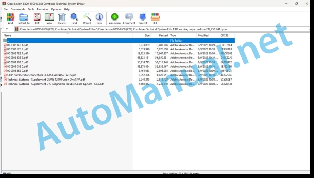
File List:
00 0302 343 1.pdf
00 0302 565 2.pdf
00 0302 782 1.pdf
00 0302 805 2.pdf
00 0303 118 0.pdf
00 0305 018 0.pdf
00 0305 863 0.pdf
CHP-numbers for connectors CLAAS HARNESS PARTS.pdf
Technical Systems – Supplement CEMIS 1200 Fusion One SPA.pdf
Technical Systems – Supplement DTC Diagnostic Trouble Code Typ C89 – C83.pdf
00 0302 343 1.pdf:
PROFI CAM 3
Table of contents
General information
Marking of warnings and hazard prevention notes
First-aid measures
CCN explanation
CCN (CLAAS Component Number)
Electric system standard
Overview
Hydraulic system standard
Overview
CCN (CLAAS Component Number)
10 Electrical / Electronic equipment
1030 Board computer / Indicators
Camera system
Description of function
1097 Testing / Measuring / Adjusting
Testing / measuring / adjusting the PROFI CAM
Checking the fuse in the video channel select box (C102)
Testing the video camera connector (C055)
1098 Fault / remedy
Fault / remedy PROFI CAM
The video monitor (C101) shows no image or cannot be switched on (indicator light fails to light up)
Video monitor (C102) displays a blue image either permanently or temporarily
The video monitor image is blurred
Replacing the fuse in the video channel select box (C102)
Connection and connecting cable with video camera (C055)
00 0302 565 2.pdf:
Sensor system
Table of contents
CCN explanation
CCN (CLAAS Component Number)
Electric system standard
Overview
Hydraulic system standard
Overview
CCN (CLAAS Component Number)
Introduction
Safety rules
Safety and hazard information
10 Electrical / Electronic equipment
1097 Testing / Measuring / Adjusting
Test report of the angle sensor (0011780.x)
Application of test report
Required tools
Test report of the angle sensor (0011780.x)
Testing / Measuring / Adjusting of angle sensor (0011780.x)
1. Reason for test
2. Mechanical test of angle sensor
3. Electric test with CDS
4. Electric test with multimeter
5. Mechanical test of connecting cable
Completing the machine
Test report of position and speed sensors
Application of test report
Required tools
Sensor variants
Part numbers of speed sensors
Part number of position sensor
Test report of position and speed sensors
Testing / measuring / adjusting of position and speed sensors
1. Reason for test
2. Mechanical test
3. Electric test with CDS
4a. Installation dimensions
Check of installation dimension
Installation dimensions of gearbox speed sensor (0011 799.x) and cam speed sensor (0011 810.x)
Installation dimension of position sensor (0011 815.x)
4b. Installation position
Centring of sensor
Metal-free zone
5. Electric test with multimeter
Voltage measurement
Direction of rotation and speed sensor (0011 605.x)
Measured values table
6. Mechanical test of connecting cable
Completing the machine
Test report of the urea sensor (00 0773 207 x)
Application of test report
Required tools
Parts number of the urea sensor
Test report of the urea sensor
Testing / measuring / adjusting urea sensor
1. Reason for test
2. Mechanical test
3. Mechanical test of connecting cable
4. Electric test with multimeter
5. Component test with the CDS
00 0302 782 1.pdf:
MAN D2676-R6LE 13x / LE 14x
Table of contents
Introduction
Safety rules
Safety and hazard information
Validity of manual
Validity of manual
General information
Marking of warnings and hazard prevention notes
Safety routines
First-aid measures
CCN explanation
CCN (CLAAS Component Number)
CCN (CLAAS Component Number)
01 Engine
0125 Injection / Fuel system
System description
Schematic layout of common rail system
Schematic layout of SCR dosing system
High-pressure pump
High-pressure pump CP3.4
Proportioning unit ZME (Y332-MAN)
Pin assignment
High-pressure accumulator (rail)
Pressure relief valve
Rail pressure sensor (B487-MAN, B514-MAN)
Connector pin assignment
Injector (Y341-MAN – Y346-MAN)
0135 Cooling system
Compensating tank coolant level sensor
Connector pin assignment
0155 Engine control
Control unit EDC17 (A435-MAN)
Connector pin assignment of control unit EDC17
Control unit connector A
Control unit connector B
Control unit connector C
Control unit connector D
Crankshaft sensor (incremental speed sensor) (B488-MAN)
Connector pin assignment
Circuit diagram
Camshaft sensor (segment speed sensor) (B489-MAN)
Connector pin assignment
Circuit diagram
Oil pressure sensor (B104-MAN)
Characteristic sensor curve
Connector pin assignment
Fuel pressure sensor (B377-MAN)
Characteristic sensor curve
Connector pin assignment
Air mass meter PFM
Connector pin assignment
Charge pressure/temperature sensor (B623-MAN)
Connector pin assignment
Coolant temperature sensor (B124-MAN)
Connector pin assignment
Circuit diagram
Charge air temperature sensor (B123-MAN)
Connector pin assignment
Circuit diagram
VTG charger (exhaust turbo charger)
VTG actuator pin assignment
VTG speed sensor pin assignment
0165 Exhaust gas aftertreatment
Exhaust treatment system
System diagram of in-line engine with SCR
Intake air temperature sensor
Connector pin assignment
Exhaust gas thermocouple elements (A1191-MAN)
Connector pin assignment
EGR linear motor (M289-MAN)
Connector pin assignment
Lambda probe (B322-MAN)
Connector pin assignment
Conveying module (A808-MAN)
Connector pin assignment
Dosing module (A1279-MAN)
Connector pin assignment
Tank heating valve (Y437-MAN)
Connector pin assignment
Combined AdBlue sensor (A1192-MAN)
Connector pin assignment
NOx sensor I (raw emissions) (B1055-MAN)
Connector pin assignment
NOx sensor II (diagnosis) (B994-MAN)
Connector pin assignment
Diesel particulate filter differential pressure sensor
Connector pin assignment
Circuit diagram
10 Electrical / Electronic equipment
1080 Electrical circuit diagram
Electric circuit diagram of control unit EDC17
1085 Networks
Overview of CAN bus and power supply
90 Miscellaneous
9090 Diagnostic
HD-OBD diagnostic socket (X200-MAN)
Fault memory
CDS fault display
FMI (Failure Mode Identification)
Test step list of control unit EDC17
1. Measurements on engine control unit EDC17
Rev-up test
Description
Compression test
Description
Cylinder shut-off test Description
High-pressure test
Description
Injector test
Reset the pressure relief valve
Description
Pressure relief valve test
Description
SCR dosing quantity test
Description
Resetting SCR system faults
Description
System test of SCR dosing system
Description
Resetting the inducement counter
Description
Fuel diagram
D26 engine fuel quick reference diagram
Troubleshooting in CAN network
1. NOx sensor I (raw emissions)
2. EGR actuator unit
3. NOx sensor II (diagnosis)
4. Thermoelements
5. Combined AdBlue sensor
Troubleshooting program
SCR dosing system troubleshooting
General overview
Speed plausibility / blocked pump
Leaky suction line
Blocked return line
SPN 94- FMI 1: Fuel supply pressure above normal
SPN 94- FMI 2: Fuel supply pressure below normal
SPN 98 – FMI 1: Engine oil level to high
SPN 98 – FMI 2: Engine oil level too low
SPN 98 – FMI 3: Engine oil levelausible
SPN 100 – FMI 1: Engine oil pressure too high
SPN 100 – FMI 2: Engine oil pressure too low
SPN 102 – FMI 1: Charge air pressure upstream of engine (in charge air tube) above normal
SPN 102 – FMI 1: Charge air pressure upstream of engine (in charge air tube) below normal
SPN 102 – FMI 3: Signal of charge air pressure upstream of engine (in charge air tube) is erratic
SPN 102 – FMI 8: Invalid signal of charge air pressure upstream of engine (in charge air tube)
SPN 105 – FMI 1: Charge air temperature upstream of cylinder intake (downstream of EGR feeding) above normal
SPN 105 – FMI 2: Charge air temperature upstream of cylinder intake (downstream of EGR feeding) below normal
SPN 105 – FMI 8: Invalid signal of charge air temperature upstream of cylinder intake (downstream of EGR feeding)
SPN 110 – FMI 1: Coolant temperature above normal
SPN 110 – FMI 2: Coolant temperature below normal
SPN 168 – FMI 1: Battery voltage above normal
SPN 168 – FMI 2: Battery voltage below normal
SPN 168 – FMI 5: Battery voltage short-circuit to earth
SPN 168 – FMI 6: Short circuit to battery voltage
SPN 171 – FMI 1: Ambient air temperature above normal
SPN 171 – FMI 2: Battery voltage below normal
SPN 174 – FMI 1: Fuel temperature above normal
SPN 174 – FMI 3: Fuel temperature is erratic
SPN 609 – FMI 4: Missing signal on engine CAN bus
SPN 609 – FMI 8: Invalid signal on engine CAN bus
SPN 651 – FMI 7: Short-circuit in current path – solenoid valve 1
SPN 651 – FMI 9: Device fault – solenoid valve 1
SPN 651 – FMI 10: Interrupted current path – solenoid valve 1
SPN 652 – FMI 7: Short-circuit in current path – solenoid valve 5
SPN 652 – FMI 9: Device fault – solenoid valve 5
SPN 652 – FMI 10: Interrupted current path – solenoid valve 5
SPN 653 – FMI 7: Short-circuit in current path – solenoid valve 3
SPN 653 – FMI 9: Devi fault – solenoid valve 3
SPN 653 – FMI 10: Interrupted current path – solenoid val SPN 654 – FMI 7: Short-circuit in current path – solenoid valve 6
SPN 654 – FMI 9: Device fault – solenoid valve 6
SPN 654 – FMI 10: Interrupted current path – solenoid valve 6
SPN 655 – FMI 7: Short-circuit in current path – solenoid valve 2
SPN 655 – FMI 9: Device fault – solenoid valve 2
SPN 655 – FMI 10: Interrupted current path – solenoid valve 2
SPN 656 – FMI 7: Short-circuit in current path – solenoid valve 4
SPN 656 – FMI 9: Device fault – solenoid valve 4
SPN 656 – FMI 10: Interrupted current path – solenoid valve 4
SPN 1079 – FMI 8: Short-circuit of sensor power supply 6
SPN 1080 – FMI 8: Short-circuit of sensor power supply 4
SPN 1131 – FMI 1: Charge air temperature upstream of engine (in charge air tube) above normal
SPN 1131 – FMI 2: Charge air temperature upstream of engine (in charge air tube) below normal
SPN 1131 – FMI 8: Invalid signal of charge air temperature upstream of engine (in charge air tube)
SPN 1761 – FMI 3: Urea level signal is erratic
SPN 1761 – FMI 8: Invalid urea level signal
SPN 3004 – FMI 4: EGR flap blocked
SPN 3005 – FMI 1: Position of exhaust recirculation flap (EGR) is above normal
SPN 3005 – FMI 2: Position of exhaust recirculation flap (EGR) is below normal
SPN 3009 – FMI 1: Engine speed above normal
SPN 3014 – FMI 3: Implausible signal between control units and main relay
SPN 3046 – FMI 3: Atmospheric pressure sensor signal is erratic
SPN 3046 – FMI 4: Atmospheric pressure sensor signal faulty
SPN 3046 – FMI 5: Atmospheric pressure sensor – short-circuit to earth
SPN 3046 – FMI 6: Atmospheric pressure sensor – short-circuit to battery plus
SPN 3046 – FMI 11: Loose atmospheric pressure sensor contact
SPN 3060 – FMI 4: EGR flap – no signal
SPN 3060 – FMI 8: EGR flap – invalid signal
SPN 3076 – FMI 8: Immobilizer – incorrect code
SPN 3077 – FMI 3: Immobilizer – code not available
SPN 3082 – FMI 1: Oil pressure sensor too high signal
SPN 3082 – FMI 2: Oil pressure sensor too low signal
SPN 3083 – FMI 1: Rail pressure sensor too high signal
SPN 3083 – FMI 2: Rail pressure sensor too low signal
SPN 3083 – FMI 3: Rail pressure sensor signal implausible
SPN 3087 – FMI 1: Oil pressure sensor signal above normal
SPN 3087 – FMI 3: Oil pressure sensor signal is erratic
SPN 3087 – FMI 4: Oil pressure sensor signal missing
SPN 3087 – FMI 5: Oil pressure sensor short-circuit to earth
SPN 3087 – FMI 11: Loose oil pressure sensor contact
SPN 3087 – FMI 5: Oil pressure sensor – broken line or short-circuit to plus
SPN 3088 – FMI 3: Charge pressure sensor signal is erratic
SPN 3088 – FMI 5: Charge pressure sensor short-circuit to earth
SPN 3088 – FMI 11: Loose charge pressure sensor contact
SPN 3088 – FMI 12: Charge pressure sensor – broken line or short-circuit to plus
SPN 3089 – FMI 3: Charge air temperature sensornal is erratic
SPN 3089 – FMI 5: Charge air temperature sensor short- 3089 – FMI 6: Charge pressure sensor short-circuit to plus
SPN 3089 – FMI 10: Charge air temperature sensor broken line
SPN 3089 – FMI 11: Loose charge air temperature sensor contact
SPN 3089 – FMI 12: Charge pressure sensor – broken line or short-circuit to plus
SPN 3091 – FMI 3: Coolant temperature sensor signal is erratic
SPN 3091 – FMI 4: Coolant temperature sensor signal missing
SPN 3091 – FMI 5: Coolant temperature sensor short-circuit to earth
SPN 3091 – FMI 6: Coolant temperature sensor short-circuit to plus
SPN 3091 – FMI 10: Coolant temperature sensor broken line
SPN 3091 – FMI 11: Loose coolant temperature sensor contact
SPN 3099 – FMI 12: Rail pressure sensor – broken line or short-circuit to plus
SPN 3099 – FMI 13: Rail pressure sensor – broken line or short-circuit to earth
SPN 3100 – FMI 3: Fuel pressure sensor signal is errati00 – FMI 4: Fuel pressure sensor signal missing
SPN 3100 – FMI 11: PN 3100 – FMI 12: Fuel pressure sensor – broken line or short-circuit to plus
SPN 3100 – FMI 13: Fuel pressure sensor – broken line or short-circuit to earth
SPN 3456 – FMI 2: Urea level < 10 %
SPN 3457 - FMI 2: Low urea level
SPN 3752 - FMI 4: No camshaft sensor signal
SPN 3752 - FMI 5: Camshaft sensor short circuit to earth
SPN 3752 - FMI 6: Camshaft sensor short circuit to positive
SPN 3753 - FMI 4: No crankshaft sensor signal
SPN 3753 - FMI 5: Crankshaft sensor short circuit to earth
SPN 3753 - FMI 6: Crankshaft sensor short circuit to positive
SPN 3753 - FMI 8: Crankshaft sensor faulty signal
SPN 3753 - FMI 10: Crankshaft sensor interruption
SPN 3775 - FMI 1: Rail pressure too high
SPN 3775 - FMI 2: Rail pressure too low
SPN 3776 - FMI 1: Positive rail pressure control difference
SPN 3778 - FMI 1: Rail pressure l pushing conditions
SPN 3780 - FMI 1: Rail pressure leakage when idlingn
SPN 3797 - FMI 5: Lambda probe heating short circuit to earth
SPN 3797 - FMI 6: Lambda probe heating short circuit to positive
SPN 3797 - FMI 10: Lambda probe heating interruption
SPN 3823 - FMI 3: Misfiring on several cylinders
SPN 3824 - FMI 3: Cylinder 1 misfiring
SPN 3825 - FMI 3: Cylinder 5 misfiring
SPN 3826 - FMI 3: Cylinder 3 misfiring
SPN 3827 - FMI 3: Cylinder 6 misfiring
SPN 3828 - FMI 3: Cylinder 2 misfiring
SPN 3829 - FMI 3: Cylinder 4 misfiring
SPN 3837 - FMI 1: Lambda probe oxygen signal above normal
SPN 3837 - FMI 2: Lambda probe oxygen signal below normal
SPN 3843 - FMI 3: Coolant temperature sensor signal is erratic
SPN 3843 - FMI 8: Invalid coolant temperature
SPN 3845 - FMI 3: Ambient temperature is erratic
SPN 3847 - FMI 3: Charge pressure/temperature sensor signal is erratic
SPN 3847 - No charge pressure/temperature sensor signal
SPN 3847 - FMI 5: Charge pressure/temperature sensor ng SPN 3847 - FMI 6: Charge pressure/temperature sensor short circuit to positive
SPN 3847 - FMI 10: Charge pressure/temperature sensor interruption
SPN 3847 - FMI 11: Charge pressure/temperature sensor loose contact
SPN 3848 - FMI 3: Ambient air temperature sensor signal is erratic
SPN 3848 - FMI 5: Ambient air temperature sensor - short-circuit to earth
SPN 3848 - FMI 6: Ambient air temperature sensor - short-circuit to plus
SPN 3848 - FMI 10: Ambient air temperature sensor - broken line
SPN 3848 - FMI 11: Loose ambient air temperature sensor contact
SPN 3855 - FMI 5: Lambda probe sensor lines short circuit to earth
SPN 3855 - FMI 6: Lambda probe sensor lines short circuit to positive
SPN 3856 - FMI 1: Lambda probe calibration too high
SPN 3856 - FMI 2: Lambda probe calibration too low
SPN 3857 - FMI 3: Lambda pion unit implausible values
SPN 3858 - FMI 1: Lambda probe temperature too high
SPN 3858 - FM SPN 3859 - FMI 1: Calibration of the Lambda probe temperature is too high
SPN 3859 - FMI 2: Calibration of the Lambda probe temperature is too low
SPN 3919 - FMI 7: NOx sensor downstream of exhaust treatment: heater fault status (short-circuit)
SPN 3919 - FMI 10: NOx sensor downstream of exhaust treatment: heater fault status (broken line)
SPN 3920 - FMI 3: NOx sensor downstream of exhaust treatment: NOx concentration fault status
SPN 3920 - FMI 7: NOx sensor downstream of exhaust treatment: NOx concentration fault status (short-circuit)
SPN 3920 - FMI 10: NOx sensor downstream of exhaust treatment: NOx concentration fault status (broken line)
SPN 3921 - FMI 1: NOx sensor downstream of exhaust treatment: Lambda signal fault status
SPN 3921 - FMI 2: NOx sensor downstream of exhaust treatment: Lambda signal fault status
SPN 3921 - FMI 3: NOx sensor downstream of exhaust treatment: Lambda signal fault status
SPN 3926 - FMI 11: Loose rail pressure sensor contact
SPN 3927 - FMI 9: Lambda probe is not installed in exhaust gas pipe
SPN 3929 - FMI 1: EGR Lambda control deviation
SPN 3929 - FMI 2: EGR Lambda control deviation
SPN 3930 - FMI 1: EGR Lambda control deviation
SPN 3938 - FMI 1: Lambda probe cannot be adapted
SPN 3938 - FMI 2: Lambda probe cannot be adapted
SPN 3938 - FMI 3: Lambda probe cannot be adapted
SPN 3938 - FMI 8: Lambda probe cannot be adapted
SPN 3972 - FMI 1: NOx value above normal
SPN 3972 - FMI 2: NOx value below normal
SPN 3972 - FMI 2: NOx value below normal
SPN 4039 - FMI 5: Short-circuit of actuator group 0 supply voltage
SPN 4039 - FMI 6: Short-circuit of actuator group 0 supply voltage
SPN 4040 - FMI 5: Short-circuit of actuator group 1 supply voltage
SPN 4040 - FMI 6: Short-circuit of actuator group 1 supply voltage
SPN 4041 - FMI 5: Short-circuit of actuator group 2 supply voltage
SPN 4041 - FMI 6: Short-circuit of actuator group 2 supply voltage
SPN 4070 - FMI 8: EDC control unit internal communication fault (with module CY146)
SPN 4071 - FMI 8: EDC control unit internal communication fault (with module CY146)
SPN 4072 - FMI 8: EDC control unit internal communication fault (with module CY146)
SPN 4073 - FMI 8: EDC control unit internal communication fault (with module CY317)
SPN 4074 - FMI 8: EDC control unit internal communication fault (with module CY320)
SPN 4400 - FMI 9: De-icing of urea system failed (device fault)
SPN 4400 - FMI 9: De-icing of AdBlue system failed (device fault)
SPN 4401 - FMI 8: Urea system: Dosing
SPN 4400 - FMI 9: Urea system: Dosing
SPN 4409 - FMI 9: Sensor power supply 5: short-circuit to earth or plus
SPN 4439 - FMI 1: Urea tank heater: temperature above normal
SPN 4439 - FMI 5: Urea tank heater: output stage fault
SPN 4439 - FMI 6: Urea tank heater: output stage fult
SPN 4439 - FMI 10: Urea tank heater: output stage fault
SPN 4447 - FMI 8: Sensor power supply 1: short-circuit
SPN 4448 -8: Sensor power supply 2: short-circuit
SPN 4449 - FMI 8: Sensor power supply 3: short-circuit
SPN 4469 - FMI 1: NOx limit exceeded
SPN 6140 - FMI 5: Airless dosing system (pressure sensor) - short-circuit to earth
SPN 6140 - FMI 6: Airless dosing system (pressure sensor) - short-circuit (UBat)
SPN 6140 - FMI 11: Airless dosing system (pressure sensor) - (loose contact)
SPN 6142 - FMI 5: Airless dosing system (temperature sensor) - short-circuit to earth
SPN 6142 - FMI 6: Airless dosing system (temperature sensor) - short-circuit to UBat
SPN 6142 - FMI 11: Airless dosing system (temperature sensor) - loose contact
SPN 6143 - FMI 6: Urea dosing valve - short-circuit to UBat
SPN 6143 - FMI 7: Urea dosing valve - short-circuit
SPN 6143 - FMI 12: Urea dosing valve - short-circuit or broken line to plus
SPN 6143 - FMI 13: Urea dosing valve - short-circuit to earth or interruption
SPN 6151 - FMI 1: PTC heater output stage
SPN 6151 - FMI 2: PTC output stage
SPN 6151 - FMI 5: PTC output stage - short-circuit (earth)
SPN 6151 - FMI 6: PTC output stage - short-circuit (UBat)
SPN 6151 - FMI 10: PTC output stage - interruption (open load)
SPN 6161 - FMI 1: SCR pump blocked
SPN 6161 - FMI 2: Pressure and speed correlation of SCR pump
SPN 6163 - FMI 1: Pressure and speed correlation of SCR pump in service routine
SPN 6163 - FMI 2: Pressure and speed correlation of SCR pump in service routine
SPN 6163 - FMI 3: Pressure and speed correlation of SCR pump in service routine
SPN 6164 - FMI 9: Dosing unit device fault
SPN 6165 - FMI 3: Pressure and speed correlation of SCR pump
SPN 6166 - FMI 1: SCR pump speed
SPN 6166 - FMI 3: SCR pump speed
SPN 6170 - FMI 9: SCR pump device fault
SPN 6171 - FMI 1: Replacing the SCR pump filter
SPN 6172 - FMI 1: SCR pump filter is full
SPN 6197 - FMI 5: Airless dosing system (speed feedback)
SPN 6197 - FMI 6: Airless dosing system (speed feedback)
SPN 6207 - FMI 1: Conveying module output stage
SPN 6207 - FMI 5: Urea dosing pump output stage - short-circuit to earth
SPN 6207 - FMI 6: Urea dosing pump output stage - short-circuit to UBat
SPN 6207 - FMI 10: Urea dosing pump output stage - interruption
SPN 6212 - FMI 9: De-icing of AdBlue system failed - device fault
92 Diagnosis
9220 Error codes engine (J1939)
Diesel engine SPN list
Fault codes
SPN list SCR dosing system
Fault codes
Position of components
Electric system
A435-MAN Engine control module
Component
Installation locations
High-pressure pump
Component
Installation location
Proportioning unit (ZME)
Component
Installation location
High-pressure accumulator (rail)
Component
Installation location
Pressure relief valve
Component
Installation location
Rail presure sensor (B487-MAN)
Component
Installation location
Injectors (Y34x-MAN)
Component
Installation location
-MAN Crankshaft sensor (incremental speed sensor)
Component
Installation location
Camshaft sensor (B489-MAN)
Component
Installation location
Oil pressure sensor (B104-MAN)
Component
Installation location
Fuel pressure sensor (B377-MAN)
Component
Installation location
Air mass meter PFM
Component
Installation location
Charge pressure/temperature sensor (B623-MAN)
Component
Installation location
Charge air temperature sensor (B123-MAN)
Component
Installation location
Coolant temperature sensor (B124-MAN)
Component
Installation location
VTG exhaust turbo charger
Component
Installation location
Intake air temperature sensor
Component
Installation location
Diesel particulate filter differential pressure sensor
Component
Installation location
Exhaust gas thermocouple elements (A1191-MAN)
Component
Installation location
EGR linear motor (M289-MAN)
Component
Installation location
Lambda probe (B322-MAN)
Component
Installation location
Conveying module (A808-MAN)
Component
Installation location
Dosing module (A1279-MAN)
Component
Installation location
Tank heating valve (Y437-MAN)
Component
Installation location
Combined AdBlue sensor (A1192-MAN)
Component
Installation location
NOx sensor I (raw emissions - B1055-MAN)
Component
Installation location
B994-MAN NOx sensor II (diagnosis)
Component
Installation location
00 0305 863 0.pdf:
LEXIONJAGUARXERION
Table of contents
Introduction
Notes on the manual
Validity of manual
Information about this Technical Sysems Manual
Identifying warnings
Hazard signs
Signal word
01 Engine
0125 Injection / Fuel system
Injection / fuel system
Required tools and aids
Line valves for connecting to the e
Valves and adapters for tank feed and return lines
Measuring setup (possible variant)
Test procedure
A – Leakage test of tank return line and possibly of tank suction line
B – Leakage test of feed lines (possibly including fuel sediment filter)
C – Test of non-return valve in the line (if provided)
D – Leakage test of return lines (possibly including the fuel cooler)
E – Leakage test of fuel sediment filter
F – Leakage test of engine
Steps 1 – 3
Fuel diagrams
Remarks about the circuit diagrams
LEXION fuel diagram
Key to diagram
JAGUAR with Mercedes-Benz OM47x LA
Key to diagram
JAGUAR with MAN D2862 (V12)
Key to diagram
CHP-numbers for connectors CLAAS HARNESS PARTS.pdf:
CLAAS HARNESS PARTS
Table of contents
10 Electrical / Electronic equipment
1081 Overview of connectors
CLAAS HARNESS PARTS (CHP)
Technical Systems – Supplement CEMIS 1200 Fusion One SPA.pdf:
01_Supplement to the system technology documents C8x_new
1_Validity Fusion one
4_SCM 110a CAN5
5_Table SCM 110a CAN5
6_SCM 330a Fusion One
7_Table SCM 330a Fusion one
Technical Systems – Supplement DTC Diagnostic Trouble Code Typ C89 – C83.pdf:
DTC: C89 – C83
General information
Marking of warnings and hazard prevention notes
First-aid measures
92 Diagnosis
9210 Error codes machine
FMI (Failure Mode Indicator)
FMI 00 (Signal too high)
FMI 01 (Signal too low)
FMI 02 (Erratic signal)
FMI 03 (Voltage too high)
FMI 04 (Voltage too low)
FMI 05 (Current too low)
FMI 06 (Current too high)
FMI 07 (Mechanical failure)
FMI 08 (Abnormal frequency signal)
FMI 09 (Communication error)
FMI 10 (Rate of signal change too fast)
FMI 11 (multiple faults)
FMI 12 (ECU defective)
FMI 13 (Signal outside of calibration range)
FMI 16 (Parameter not available)
FMI 17 (ECU not responding)
FMI 18 (Power supply failure)
FMI 19 (Software conditions not met)
FMI 95 (no signal change)
FMI 96 (CAN Bus system defective)
FMI 97 (Erratic condition)
FMI 98 (Warning)
FMI 99 (Info)
John Deere Repair Technical Manual PDF
John Deere Repair Technical Manual PDF
John Deere 18-Speed PST Repair Manual Component Technical Manual CTM168 10DEC07
John Deere Repair Technical Manual PDF
New Holland Service Manual PDF
John Deere Repair Technical Manual PDF
John Deere Diesel Engines PowerTech 4.5L and 6.8L – Motor Base Technical Manual 07MAY08 Portuguese
John Deere Parts Catalog PDF
John Deere Harvesters 8500 and 8700 Parts Catalog CPCQ24910 Spanish
John Deere Repair Technical Manual PDF
John Deere Repair Technical Manual PDF
John Deere Repair Technical Manual PDF
John Deere Repair Technical Manual PDF

