Claas Liner 390 S (600) Swathers Assembly Instruction EN
$50.00
- Model: Liner 390 S (600) Swathers
- Type Of Manual: Assembly Instruction
- Language: EN
- Format: PDF(s)
- Size: 49.8 MB
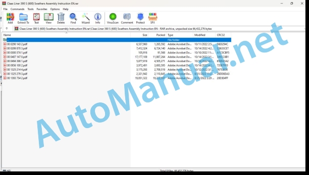
File List:
00 0290 143 2.pdf
00 0299 870 3.pdf
00 0300 374 1.pdf
00 0487 147 0.pdf
00 0494 396 1.pdf
00 0956 100 2.pdf
00 1325 214 4.pdf
00 1325 279 3.pdf
00 1393 754 2.pdf
00 0299 870 3.pdf:
1 Basic components of the machine
2 Introduction
Introduction
Validity
3 Contents
4 Preface
Of special importance
Identification Plate
5 Safety Rules
Intended use
Avoidable incorrect applications
General safety regulations and safety precautions
De-commissioning and disposal
Identification of warning and hazard signs
Safety Decals with warning symbols
6 Technical data
LINER 470 S
LINER 430 S
LINER 390 S
LINER 350 S
Calculation of axle loads, minimum ballasting and total weight
Calculation of minimum ballasting at the front
Calculation of minimum ballasting at the rear
Calculation of the real front axle load
Calculation of the real total weight
Calculation of the real rear axle load
Tyre load carrying capacity
7 Assembly
Loading and unloading machine
Initial assembly of machine
Assembly Instructions
Mounting the warning panels
8 Prior to operation
Check every time prior to operation
Hitching up
Headstock
Universal drive shaft
Swath disc
Lowering the machine
Prior to transportation
Driving on public roads
Identification of the machine for road traffic
Warning plates with lighting
9 Operation
Field operation
Working position
Adjusting the swathing deflector
Height adjustment of the rotary assembly
Swath forming adjustment
Putting the swather to work
Transport position
Optional Equipment
3-point linkage – gauge wheel
Universal joint yoke kit
10 Maintenance
Important maintenance instructions
Wheels and tyres
Lubrication
Safety frame
Rotor gearcase
Swather gearbox LINER 470 S / 430 S / 390 S
Sealing the rotor gearcase
Clamping bearing – version with seal already applied
Clamping bearing – version without seal already applied
Swather gearbox LINER 350 S
PTO drive shaft
Screw connections
Spring tines
Fasteners
Cleaning and care
Winter storage
11 Lubrication chart
Safety precaution
Lubricating grease
Lubrication
00 0487 147 0.pdf:
Elektro-hydraulischer Kreisel-Einzelaushub
Electro-hydraulic individual rotor lift
Individual electro-hydraulic lifting of tops
Single electrohydraulic lifting of the rotors
Individual electro-hydraulic lifting of the windrow rotors
Электрогидравлический оделанный помед валкового ротора
Allgemeine Hinweise
Sicherheitshinweise
Handhandung der Anleitung
Symbole Warnhinweise
General instructions
Safety precautions
Handling of manual
Symbols and warnings
General remarks
Security advice
Use of the notice
Warning symbols
General warning
Safety standard
Use of the Instruction Manual
Danger warning symbol
General indications
Safety instructions
Пользование Руководством
Warning symbols
00 0494 396 1.pdf:
1 Introduction
1.1 Allgemeine Hinweise
1.1.1 Handling the instructions
1.1.2 Gültigkeit der Anleitung
2 Safety
2.1 Beachten
2.1.1 Besonders zu beachten
2.1.2 Kennzeichnung von Warn- und Gefahrenhinweinwesen
3 Scope of delivery
3.1 Bügelsicherung für Zinkenträger
3.1.1 Teilesatz 000 494 395 0 – LINER 1550 TWIN Profile
3.1.2 Teilesatz 000 494 394 0 – LINER 780 Profile
3.1.3 Teilesatz 000 494 389 0 – LINER 470 T / 470 S
3.1.4 Teilesatz 000 494 388 0 – LINER 430 S
3.1.5 Teilesatz 000 494 387 0 – LINER 390 S
4.1 Umbau der Zinkenträger
4.1.1 Zinkenträger dismantle
4.1.2 Bügelsicherung für Zinkenträger montieren
4.1.3 Zinken mounted
4.2 Additional work – LINER 1550 TWIN Profile
4.2.1 Verriegelung Radachsen abtrennen
4.3 Supplementary work -S, LINER 390 S
4.3.1 Unterlegkeile versezen
4.3.2 Haeren
4.4 Before Commissioning
4.4.1 Check and observe before commissioning
1 Introduction
1.1 General Information
1.1.1 How to use this manual
1.1.2 Validity of instructions
2 Safety precautions
2.1 Important
2.1.1 Important information
2.1.2 Identification of warning and danger signs
3 Package list
3.1 Clamp-type safeguard for tine carriers
3.1.1 Parts kit 000 494 395 0 – LINER 1550 TWIN Profile
3.1.2 Parts kit 000 494 394 0 – LINER 780 Profile
3.1.3 Parts kit 000 494 389 0 – LINER 470 T / 470 S
3.1.4 Parts kit 000 494 388 0 – LINER 430 S
3.1.5 Parts kit 000 494 387 0 – LINER 390 S
4 Conversion
4.1 Conversion of tine carriers
4.1.1 Dismounting the tine carriers
4.1.2 Installing the clamp-type safeguard for tine carriers
4.1.3 Mounting the tubs
4.2 Supplementary work – LINER 1550 TWIN Profile
4.2.1 Removing the wheel axle locks
4.3 Supplementaryork – LINER 470 T / 470 S, LINER 430 S, LINER 390 S
4.3.1 Relocating the wheel chocks
4.3.2 Installing the brackets for tine carriers
4.4 Prior to operation
4.4.1 Items to check and observe before operation
1 Introduction
1.1 General advice
1.1.1 Use of the notice
1.1.2 Validity of the notice
2 Safety advice
2.1 Observe!
2.1.1 Important
2.1.2 Marking of warnings and dangers
3 pieces provided
3.1 Sécurité d’étrier pour porte-dents
3.1.1 Set of parts 000 494 395 0 – LINER 1550 TWIN Profile
3.1.2 Set of pieces 000 494 394 0 – LINER 780 Profile
3.1.3 Set of parts 000 494 389 0 – LINER 470 T / 470 S
3.1.4 Set of parts 000 494 388 0 – LINER 430 S
3.1.5 Set of parts 000 494 387 0 – LINER 390 S
4 Modification of the assembly
4.1 Modification of tooth holders
4.1.1 Disassemble the tooth holders
4.1.2 Mount the caliper safety for the tooth holders
4.1.3 Mount the teeth
4.2 Additional work – LINER 1550 TWIN Profile
4.2.1 Unlock the wheels
.3 Additional work – LINER 470 T / 470 S, LINER 430 S, LINER 390 S
4.3.1 Decaler the brake shoes 4.3.2 Mount the supports for the tooth holders
4.4 Before commissioning
4.4.1 Before putting the machine into service, check the following points
1 Introduction
1.1 General indications
1.1.1 Application of the user manual
1.1.2 Validity of the user manual
2 Security
2.1 To be observed
2.1.1 Important notice
2.1.2 Signaling of warning and danger
3 Complesivo di forniture
3.1 Safety bracket for tooth holder frame
3.1.1 Set of parts 000 494 395 0 – LINER 1550 TWIN Profile
3.1.2 Set of parts 000 494 394 0 – LINER 780 TWIN Profile
3.1.3 Set of parts 000 494 389 0 – LINER 470 T / 470 S
3.1.4 Set of parts 000 494 388 0 – LINER 430 TWIN Profile
3.1.5 Set of parts 000 494 387 0 – LINER 390 TWIN Profile
4 Modify
4.1 Modification of the tooth holder frame
4.1.1 Assembly of the tooth frame
4.1.2 Montaggio della sicurezza staffa for i portadenti frame
4.1.3 Assembly of the teeth
4.2 Complementary work – LINER 1550 TWIN Profile
4.2.1 Release the wheel lock
4.3 Additional work – LINER 470 T / 470 S, LINER 430 S, LINER 390 S
4.3.1 Spostare il cuneo
4.3.2 Assembling and supporting the denture frame
4.4 Commissioning fee
4.4.1 Before putting it into operation, perform the following checks and observe the prescriptions
1 Introduction
1.1 General indications
1.1.1 Use of the instructions
1.1.2 Validity of the instructions
2 Security measures
2.1 Observe
2.1.1 Especially important
2.1.2 Signaling of warnings and dangers
3 Supply set
3.1 Stirrup lock for pick holder
3.1.1 Set of parts 000 494 395 0 – LINER 1550 TWIN Profile
3.1.2 Set of parts 000 494 394 0 – LINER 780 Profile
3.1.3 Set of parts 000 494 389 0 – LINER 470 T / 470 S
3.1.4 Set of parts 000 494 388 0 – LINER 430 S
3.1.5 Set of parts 000 494 387 0 – LINER 390 S
4 Transformation
4.1 Transformation of the toothpick holders
4.1.1 Disassemble the fork holders
4.1.2 Assemble the safety stirrup for the fork holders
4.1.3 Mount the spikes
4.2 Additional work – LINER 1550 TWIN Profile
4.2.1 Separate the lock from the wheel axles
4.3 Additional work – LINER 470 T / 470 S, LINER 430 S, LINER 390 S
4.3.1 Change the position panties
4.3.2 Mount the supports for the knife holders
4.4 Before commissioning
4.4.1 Check and take into account before start-up
John Deere Parts Catalog PDF
John Deere Tractors 7500 Parts Catalog CPCQ26568 30 Jan 02 Portuguese
John Deere Repair Technical Manual PDF
John Deere DF Series 150 and 250 Transmissions (ANALOG) Component Technical Manual CTM147 05JUN98
John Deere Repair Technical Manual PDF
John Deere Repair Technical Manual PDF
John Deere Repair Technical Manual PDF
John Deere Repair Technical Manual PDF
John Deere PowerTech M 10.5 L and 12.5 L Diesel Engines COMPONENT TECHNICAL MANUAL CTM100 10MAY11
John Deere Repair Technical Manual PDF
John Deere 18-Speed PST Repair Manual Component Technical Manual CTM168 10DEC07
John Deere Repair Technical Manual PDF
John Deere Repair Technical Manual PDF

