Claas Liner 880 (606) Swathers Operator Manual EN
$50.00
- Model: Liner 880 (606) Swathers
- Type Of Manual: Operator Manual
- Language: EN
- Format: PDF(s)
- Size: 34.3 MB
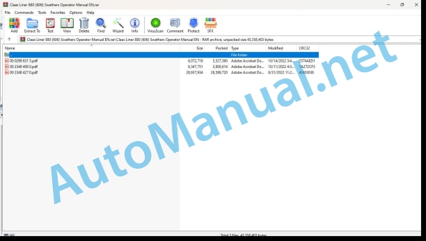
File List:
00 0299 631 5.pdf
00 2348 408 0.pdf
00 2348 427 0.pdf
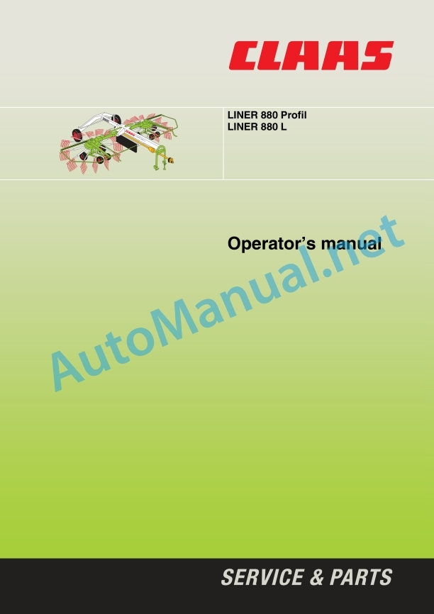
00 0299 631 5.pdf:
1 Machine description
2 Introduction
Introduction
3 Contents
4 Preface
Of special importance
Identification label
5 Safety instructions
Designated use
General safety and accident prevention regulations
Identification of warning and danger signs
Safety decals with pictorials
6 Specifications
LINER 880 Profil / 880 L
7 Assembly
Unloading/loading the machine
First machine hitch-up
8 Prior to operation
Items to check and observe before operation
Hitching
Attaching to the bottom links
Universal drive shaft
Checking and matching the drive shaft
Shortening the drive shaft
Fitting the drive shaft on the machine side
Connecting the drive shaft on the tractor side
Electrical connections
Hydraulic connections
Pull rope
Mounting the tine arms
Steering angle of hitch yoke
Parking the machine
Parking the machine at subzero temperatures
Before transport
Removing the tine arms
Road travel
9 Operation
Field operation
Lowering the rotors into working position
Putting the rotary swather into operation
Rotors in headland position
Working with a single rotor
Setting the swath width
Rotor height adjustment
Transport position
Accessory equipment
Slip yoke kit
Hydraulic couplings for tractors
Adapter for USA road lighting
10 Maintenance
Important maintenance instructions
Wheels and tyres
Hydraulic system
Screws and bolts
Lubrication
Guards (Safety Frame)
Cam drive housing
Sealing the cam drive housing
Clamping bearing with sprayed on seal
Clamping bearing without sprayed on seal
Angle drive
Drive shafts
General information concerning drive shafts
Spring adjustment
Rotor relief
Lock setting
Centrifugal running gear
Hydraulics
Hydraulic hoses
Threaded fasteners
Tine rotors
Frame / Drawbar
Hitch yoke
Spring tine
Fasteners
Quick fit connector bracket securing device
Wear discs bracket securing device
Spring bracket securing device
Safety guards
Road wheels
Checking toe-in
Checking the track
Tyre air pressure
Wheel change
Winter storage
11 Lubricating chart
Safety rules
Lubricants
Lubrication
00 2348 408 0.pdf:
CEMIS 100
Table of contents
1 Introduction
1.1 General information
1.1.1 Validity of the manual
1.1.2 Information about this Operator’s Manual
1.1.3 Symbols and notes
1.2 Intended use
1.2.1 Intended use
1.2.2 Reasonably foreseeable misuse
2 Safety
2.1 Safety rules
2.1.1 General safety and accident prevention regulations
2.1.2 Interaction between terminal and machine or tractor
2.1.3 Electrocution by electrical system
3 Product description
3.1 Overview and method of operation
3.1.1 Overview of CEMIS 100
3.1.2 Function principle of CEMIS 100
3.2 Identification plates and identification numbers
3.2.1 Spare parts and technical questions
3.2.2 Identification plate of CEMIS 100
4 Operating and display elements
4.1 CEMIS 100
4.1.1 User interface for LINER
4.1.2 User interface for ROLLANT
4.1.3 User interface for UNIWRAP
5 Technical specifications
5.1 CEMIS 100
5.1.1 Specification
6 Operation
6.1 CEMIS 100
6.1.1 Operating the CEMIS 100
6.1.2 Switching CEMIS 100 on
6.1.3 Switching CEMIS 100 off
7 Maintenance
7.1 CEMIS 100
7.1.1 Daily
8 Putting out of operation and disposal
8.1 General information
8.1.1 Removal from service and disposal
9 Technical terms and abbreviations
9.1 Terms and explanations
9.1.1 Technical words
9.1.2 Abbreviations
00 2348 427 0.pdf:
CEMIS 700
Table of contents
1 Introduction
1.1 General information
1.1.1 Validity of the manual
1.1.2 Information about this Operator’s Manual
1.1.3 Symbols and notes
1.2 Intended use
1.2.1 Intended use
1.2.2 Reasonably foreseeable misuse
2 Safety
2.1 Safety rules
2.1.1 General safety and accident prevention regulations
2.1.2 Interaction between terminal and machine or tractor
2.1.3 Electrocution by electrical system
3 Product description
3.1 Overview and method of operation
3.1.1 Overview of CEMIS 700
3.1.2 Function principle of CEMIS 700
3.2 Identification plates and identification numbers
3.2.1 Spare parts and technical questions
3.2.2 Identification plate of CEMIS 700
4 Information on the product
4.1 Software version
5 Operating and display elements
5.1 CEMIS 700
5.1.1 User interface
5.1.2 Terminal program
6 Technical specifications
6.1 CEMIS 700
6.1.1 Specification
7 Operation
7.1 CEMIS 700
7.1.1 Operating the CEMIS 700
7.1.2 Switching CEMIS 700 on
7.1.3 Switching CEMIS 700 off
7.2 Terminal settings
7.2.1 Making settings
Making settings with the rotary button
Making settings with the touch function
7.2.2 Setting the screen lighting
Daytime mode
Nighttime mode
Activating automatic key lighting
7.2.3 Setting the time and date
7.2.4 Displaying diagnosis information
On-board power supply voltage display
Display of CLAAS ISOBUS ECU address and name
7.2.5 Setting the language and display formats
Setting the language
Setting display formats
7.2.6 Setting the volume
7.2.7 Deleting an ISOBUS implement
8 Maintenance
8.1 Maintenance
8.1.1 Daily
9 Putting out of operation and disposal
9.1 General information
9.1.1 Removal from service and disposal
10 Technical terms and abbreviations
10.1 Terms and explanations
10.1.1 Technical words
10.1.2 Abbreviations
New Holland Service Manual PDF
John Deere Repair Technical Manual PDF
John Deere Parts Catalog PDF
John Deere Tractors 6300, 6500, and 6600 Parts Catalog CQ26564 (29SET05) Portuguese
John Deere Repair Technical Manual PDF
John Deere 18-Speed PST Repair Manual Component Technical Manual CTM168 10DEC07
John Deere Repair Technical Manual PDF
John Deere Repair Technical Manual PDF
John Deere Repair Technical Manual PDF
John Deere POWERTECH E 4.5 and 6.8 L Diesel Engines TECHNICAL MANUAL 25JAN08
John Deere Repair Technical Manual PDF
John Deere Repair Technical Manual PDF
John Deere Diesel Engines PowerTech 4.5L and 6.8L – Motor Base Technical Manual 07MAY08 Portuguese
John Deere Repair Technical Manual PDF


