Claas Markant 650 (776) Balers Operator Manual EN
$50.00
- Model: Markant 650 (776) Balers
- Type Of Manual: Operator Manual
- Language: EN
- Format: PDF(s)
- Size: 44.0 MB
File List:
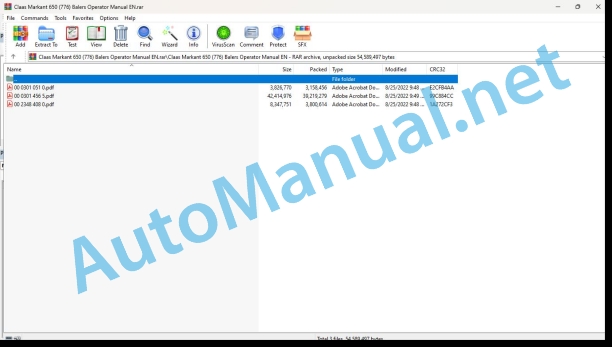
00 0301 051 0.pdf
00 0301 456 5.pdf
00 2348 408 0.pdf
00 0301 051 0.pdf:
PROFI CAM 3
Table of contents
1 Introduction
1.1 Notes on the manual
1.1.1 Validity of manual
1.1.2 Information about this Operator’s Manual
1.1.3 Symbols and notes
1.1.4 Optional equipment
1.1.5 Qualified specialist workshop
1.1.6 Maintenance information
1.1.7 Warranty notes
1.1.8 Spare parts and technical questions
1.2 Intended use
1.2.1 Intended use
1.2.2 Reasonably foreseeable misuse
2.1 Identifying warnings
2.1.1 Hazard signs
2.1.2 Signal word
2.2 Safety rules
2.2.1 Meaning of Operator’s Manual
2.2.2 Observing safety decals and warnings
2.2.3 Optional equipment and spare parts
3 Product description
3.1 Overview and method of operation
3.1.1 How the PROFI CAM works
3.2 Identification plates and identification number
3.2.1 Position of identification plates
3.2.2 Explanation of PROFI CAM identification plate
3.3 Information on the product
3.3.1 CE marking
4 Operating and control elements
4.1 Camera system
4.1.1 Camera system monitor
4.2 Menu structure
4.2.1 Main menu
4.2.2
4.2.3
4.2.4
4.2.5
4.2.6
5 Technical specifications
5.1 PROFI CAM
5.1.1 Monitor
5.1.2 Camera
5.1.3 Switch box
5.1.4 Degree of protection against foreign bodies and water
6 Preparing the product
6.1 Shutting down and securing the machine
6.1.1 Switching off and securing the machine
6.2 Prior to operation
6.2.1 Carry out prior to operation
6.2.2 Installing the sun protection
6.2.3 Aligning the camera
6.2.4 Connecting the camera electrics
7 Operation
7.1 Monitor
7.1.1 Switching on the monitor
7.1.2 Calling up the menu
7.1.3 Setting a menu item
7.1.4 Setting the image orientation
7.1.5 Setting automatic screen darkening
7.1.6 Image mirroring
7.1.7 Setting the trigger view
7.1.8 Setting the follow-up time for trigger view
7.1.9 Setting the display mode
7.1.10 Activating/deactivating a display mode
8 Faults and remedies
8.1 Electrical and electronic system
8.1.1 Overview of problems on PROFI CAM camera system
8.1.2 Replacing the switch box fuse
9 Maintenance
9.1 Maintenance intervals
9.1.1 Every 10 operating hours or daily
9.2 Camera system
9.2.1 Checking the camera system for dirt
9.2.2 Cleaning the camera
9.2.3 Cleaning the switch box
9.2.4 Cleaning the monitor
10 Placing out of operation and disposal
10.1 General Information
10.1.1 Putting out of operation and disposal
11 Technical terms and abbreviations
11.1 Abbreviations
11.1.1 Units
11.1.2 Abbreviations
11.1.3 Technical terms
00 0301 456 5.pdf:
MARKANT 6509YFQ-1.71Square baler
Table of contents
1 Introduction
1.1 General information
1.1.1 Manual validity
1.1.2 Product identification sheet – MARKANT 650
1.1.3 Information about this Operator’s Manual
1.1.4 Symbols and notes
1.1.5 Optional equipment
1.1.6 Qualified specialist workshop
1.1.7 Maintenance notes
1.1.8 Notes on warranty
1.1.9 Spare parts and technical questions
1.2 Intended use
1.2.1 Using in line with intended usage
1.2.2 Reasonably foreseeable misuse
2.1 Identifying warnings
2.1.1 Hazard signs
2.1.2 Signal word
2.2 Safety rules
2.2.1 Importance of Operator’s Manual
2.2.2 Observing safety decals and warnings
2.2.3 Requirements for all persons working with the machine
2.2.4 Children in danger
2.2.5 Hazard areas
2.2.6 Presence between tractor and machine
2.2.7 Persons riding on the machine
2.2.8 Hitching the tractor to the machine
2.2.9 Danger of injury from rotating shafts
2.2.10 Structural alterations
2.2.11 Optional equipment and spare parts
2.2.12 Controlling the tractor when it is running
2.2.13 Operation only after proper putting into operation
2.2.14 Technical condition
2.2.15 Danger from damage to the machine
2.2.16 Complying with technical limit values
2.2.17 Danger from continued running of machine parts
2.2.18 Keeping safety devices functional
2.2.19 Personal protective equipment
2.2.20 Wearing suitable clothing
2.2.21 Removing dirt and loose objects
2.2.22 Preparing the machine for road travel
2.2.23 Risks when driving on the road and in the field
2.2.24 Parking the machine safely
2.2.25 Unsupervised parking
2.2.26 Unsuitable operating utilities
2.2.27 Safe handling of operating and auxiliary utilities
2.2.28 Environmental protection and disposal
2.2.29 Avoiding fires
2.2.30 Lethal electrocution from overhead lines
2.2.31 Electrocution by electrical system
2.2.32 Pressurised fluids
2.2.33 Hot surfaces
2.2.34 Working on machine only after shutting it down
2.2.35 Maintenance work and repairs
2.2.36 Raised machine parts and loads
2.2.37 Risks related to welding work
2.3 Safety decals
2.3.1 Layout of safety decals
2.3.2 Location of safety stickers
3 Machine description
3.1 Existing models
3.1.1 Machine description
3.2 Overview and functions
3.2.1 Overview, front right-hand side
3.2.2 Overview, front left-hand side
3.2.3 Overview, rear right-hand side
3.3 Safety equipment
3.3.1 Indicator lights
3.3.2 Jack stand
3.3.3 Chocks
3.3.4 Locking the pick-up
3.3.5 Locking the bale ramp
3.4 Working and service areas
3.4.1 General points
3.5 Identification plate and serial number
3.5.1 Replacement parts and technical information
3.5.2 Identification number
3.5.3 Machine identification plate
Identification plate for China
Identification plate for a machine without European certification
3.6 General operating principle
3.6.1 Baling cycle
3.7 Transmission and drive
3.7.1 Power transmission
3.7.2 Slip clutch
3.7.3 Main drive
3.7.4 Tying device drive
3.7.5 Feed rake drive
3.7.6 Pick-up drive
3.8.1 Axle
3.9 Coupling frame
3.9.1 Coupling types
3.10 Crop feeding
3.10.1 Pick-up
3.11 Feeder unit
3.11.1 Feed rakes
3.12 Baling system
3.12.1 Piston and bale chamber
3.13 Tying system
3.13.1 Tying process
3.13.2 Twine box
3.13.3 Baling wire box*
3.13.4 Needles
3.13.5 Knotters
3.13.6 Twister*
3.14 Bale discharge
3.14.1 Bale ramp
Two-section bale ramp
3.15 Greasing system
3.15.1 Manual central lubrication*
3.16 Equipment
3.16.1 Mechanical bale counter
4 Technical specifications
4.1.1 Dimensions
4.1.2 Weight
4.1.3 Hitching
4.1.4 Universal drive shaft
4.1.5 Crop feeding
4.1.6 Feeder unit
4.1.7 Baling system
4.1.8 Bale discharge
4.1.9 Tying device
4.1.10 Wheels
4.1.11 Hydraulic circuit
4.1.12 Bolt tightening torques
4.1.13 Greasing and lubrication
4.1.14 Noise level
4.2 Safety devices
4.2.1 Shear bolts
4.2.2 Overload safety
4.3 Lubricants charts
4.3.1 Lubricants
4.4 Tractor
4.4.1 Power required
4.4.2 Power take-off
4.4.3 Hitching
4.4.4 Electrical connections
4.4.5 Hydraulic connections
4.4.6 Hydraulic oil and circuit
5 Machine preparation
5.1 General information
5.1.1 Before first use
5.1.2 Checking the equipment
5.2 Switching off and securing the machine
5.2.1 Stopping and securing the tractor and machine
5.3 Adapting the tractor
5.3.1 Checking the protective guard on the tractor PTO shaft
5.4 Adapting the machine
5.4.1 Universal drive shaft safety advice
5.4.2 Overlap of the universal drive shaft
5.4.3 Adapting the length of the universal drive shaft
5.4.4 Adapting the hitching height
5.5 Hitching the machine
5.5.1 Fitting the universal drive shaft
5.5.2 Recommendations
5.5.3 Hitching the baler to the tractor
Long drawbar*
Pivoting drawbar*
5.5.4 Connecting the hydraulic hoses
Hose identification
Pick-up hydraulic control*
Drawbar hydraulic control*
5.5.5 Connecting the lighting*
5.5.6 Control cords
5.6 Preparing fieldwork
5.6.1 Important
5.6.2 Pick-up wheel (*)
5.6.3 Pick-up height
5.7 Twine tying
5.7.1 Twine quality
5.7.2 Preparation for twine tying
5.7.3 Fitting the twine
5.7.4 Fitting the twine in the knotters
5.7.5 Checking the settings
5.8 Wire tying
5.8.1 Baling wire quality
5.8.2 Preparation for baling wire tying
5.8.3 Fitting the baling wire
5.8.4 Fitting the baling wire in the twister
5.8.5 Checking the twister settings
5.9 Bale discharge
5.9.1 Bale ramp
5.10 Loading the machine
5.10.1 Raising the baler
5.10.2 Lashing the baler
6 Operation
6.1 General information
6.1.1 Baler user
6.1.2 Opening the flaps and covers
Drive gearbox cover
Opening the drive gearbox cover
Closing the drive gearbox cover
Flywheel cover
Opening the flywheel cover
Closing the flywheel cover
Feed rake cover
Opening the feed rake cover
Closing the feed rake cover
Knotter cover
Opening the knotter cover
Closing the knotter cover
Twine box cover
Opening the twine box cover
Closing the twine box cover
6.2 Travelling with the baler
6.2.1 Checking the equipment
6.2.2 Preparing for transportation
6.2.3 Travelling on the road
6.2.4 Arriving at the field
6.2.5 Driving in fields
6.2.6 Parking
6.3 Before each usage
6.3.1 Reminders
6.3.2 Universal drive shaft
6.3.3 Baler maintenance
6.4 Commissioning in the field
6.4.1 User advice
End of swath or headland
6.4.2 Bale ramp
6.4.3 Starting the machine
6.5 Drawbar
6.5.1 Manoeuvring the drawbar
6.6 Bale parameters
6.6.1 Baler settings
6.7 Baling
6.7.1 Baling pressure setting
6.7.2 Bale length setting
6.7.3 Manually ejecting the bale
6.8 Unblocking the baler
6.8.1 How can blockages be avoided?
6.8.2 Safety advice
6.8.3 Blockage
6.9 After use
6.9.1 Reminders
6.9.2 Securing the baler
6.9.3 Unhitching the baler
6.9.4 Daily checks
6.9.5 Daily cleaning
7 Faults and remedies
7.1 Twine tying
7.1.1 Causes of tying faults
7.1.2 Resolving twine tying faults
7.2 Wire tying
7.2.1 Causes of baling wire tying faults
7.2.2 Resolving baling wire tying faults
7.3 Baling
7.3.1 Resolving baling faults
7.4 Greasing system
7.4.1 Cause of the problems
7.4.2 Resolving problems
8 Maintenance
8.1 General maintenance information
8.1.1 Maintenance and safety advice
8.1.2 Wheels and tyres
8.1.3 Hydraulic circuit
8.1.4 Chains
8.1.5 Universal drive shaft
8.2 Maintenance schedules
8.2.1 Maintenance operations before gathering crop
8.2.2 Maintenance operations after the first 10 hours of operation
8.2.3 Maintenance operations after the first 50 hours of operation
8.2.4 Maintenance operations every 10 hours of operation or every day
8.2.5 Maintenance operations every 50 hours of operation
8.2.6 Maintenance operations every 250 hours of operation
8.2.7 Maintenance operations annually or every 500 hours of operation
8.3 Basic operations
8.3.1 Baling piston at front dead centre
8.3.2 Manual rotation of the flywheel
Removing the flywheel guard
Fitting the flywheel guard
8.3.3 Manually starting tying
8.4 Basic settings
8.4.1 Baler basic settings
Checking the feed rake setting
Calibrating the inner feed rake
Calibrating the outer feed rake
Needles / piston position
Twine tying*
Baling wire tying*
Piston stop synchronisation
8.4.2 Piston knife
8.5 Maintenance operations gearbox
8.5.1 Drive gearbox
8.5.2 Drive chains
Pick-up drive chain
8.6 Maintenance operations clutch
8.6.1 Flywheel friction clutch
Friction clutch without free wheel*
Friction clutch with free wheel*
Opening the clutch
8.6.2 Pick-up slip clutch
8.6.3 Flywheel shear bolt
8.6.4 Feed rake shear bolts
8.7 Maintenance operations axle and wheels
8.7.1 Axle
8.7.2 Checking the wheel tightness
8.7.3 Changing the wheels
8.7.4 Wheel hub
8.7.5 Checking the tyres
8.8 Maintenance operations tying
8.8.1 Twine tying needles
Position of the needles in the piston
Needle pressure on the knotter
Needle height
Needle top dead centre
Needles – piston position
Replacing a needle
Needle brake
8.8.2 Needles – Baling wire tying
Needle height
Needle length
Needles / piston position
Replacing a needle
Needle brake
8.8.3 Changing the needle brake pads
Removing a needle brake
Disassembling a needle brake
Assembling a needle brake
Fitting a needle brake
Adjusting a needle brake
8.8.4 Adjusting the twine tensioner
8.8.5 Knotter settings
8.8.6 Twister settings
Lateral play for the needles
Checking the clamps
Adjusting the clamps
Baling wire box
Wire guide rollers
8.8.7 Tying control shaft shear bolt
8.9 Maintenance operations hitch
8.9.1 Checking the hitching device mounting
8.10 Lubrication plan
8.10.1 Lubrication intervals
8.10.2 Universal drive shaft
8.10.3 Lubrication points – 10 h
8.10.4 Lubrication points – 20 h
8.10.5 Lubrication points – 50 hrs
8.10.6 Lubrication points – 250 h
8.11 Winter storage
8.11.1 General points
8.11.2 Cleaning
8.11.3 Lubricating
8.11.4 Maintenance
8.11.5 Storage
9 Putting out of operation and disposal
9.1 General information
9.1.1 Removal from service and disposal
00 2348 408 0.pdf:
Table of contents
1 Introduction
1.1 General information
1.1.1 Validity of the manual
1.1.2 Information about this Operator’s Manual
1.1.3 Symbols and notes
1.2 Intended use
1.2.1 Intended use
1.2.2 Reasonably foreseeable misuse
2.1 Safety rules
2.1.1 General safety and accident prevention regulations
2.1.2 Interaction between terminal and machine or tractor
2.1.3 Electrocution by electrical system
3 Product description
3.1 Overview and method of operation
3.1.1 Overview of CEMIS 100
3.1.2 Function principle of CEMIS 100
3.2 Identification plates and identification numbers
3.2.1 Spare parts and technical questions
3.2.2 Identification plate of CEMIS 100
4 Operating and display elements
4.1 CEMIS 100
4.1.1 User interface for LINER
4.1.2 User interface for ROLLANT
4.1.3 User interface for UNIWRAP
5 Technical specifications
5.1 CEMIS 100
5.1.1 Specification
6 Operation
6.1 CEMIS 100
6.1.1 Operating the CEMIS 100
6.1.2 Switching CEMIS 100 on
6.1.3 Switching CEMIS 100 off
7 Maintenance
7.1 CEMIS 100
7.1.1 Daily
8 Putting out of operation and disposal
8.1 General information
8.1.1 Removal from service and disposal
9 Technical terms and abbreviations
9.1 Terms and explanations
9.1.1 Technical words
9.1.2 Abbreviations
New Holland Service Manual PDF
John Deere Repair Technical Manual PDF
John Deere Repair Technical Manual PDF
John Deere Parts Catalog PDF
John Deere Tractors 6300, 6500, and 6600 Parts Catalog CQ26564 (29SET05) Portuguese
John Deere Repair Technical Manual PDF
John Deere Transmission Control Unit Component Technical Manual CTM157 15JUL05
John Deere Repair Technical Manual PDF
John Deere Repair Technical Manual PDF
John Deere Repair Technical Manual PDF
John Deere DF Series 150 and 250 Transmissions (ANALOG) Component Technical Manual CTM147 05JUN98
John Deere Repair Technical Manual PDF


