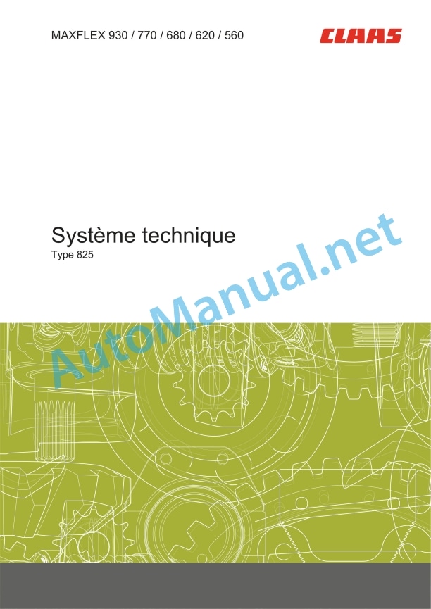
Claas Maxflex 930-560 (825) Combines Technical System FR
$150.00
- Model: Maxflex 930-560 (825) Combines
- Type Of Manual: Technical System
- Language: FR
- Format: PDF(s)
- Size: 10.1 MB
File List:
00 0306 333 0.pdf
00 0306 333 0.pdf:
Technical system
Contents
Introduction
Notes on the instructions
Validity of the notice
Information about the technical system manual
Use of the instructions
Classification in module/group structure
Seek and find
Directions
Security
Recognize the warnings
Warning pictogram
Signal word
Safety tips
Warning stickers and warnings
Requirements for specialized personnel
Children in danger
Dangerous areas of the machine
Passenger instructor during work
Risk of injury from rotating shafts
Construction modifications on the machine
Optional equipment and spare parts
Controlling the machine in operation
Technical condition
Respect the technical threshold values
Danger due to machine elements continuing to operate by inertia
Maintain safety devices in operational capacity
Personal protective equipment
Wear suitable clothing
Remove dirt and loose objects
Park and store the machine safely
Unsuitable operating consumables
Safe handling of operating consumables and secondary consumables
Environmental protection and disposal
Never put chemicals in the cabin
Avoiding fires
Fatal electrical discharges from overhead power lines and lightning strikes
Electrical discharge from the electrical system
Noise can harm your health
Machine parts under stress
Liquids under pressure
Pressurized air
Toxic exhaust gases
Hot surfaces
Safe ascent and descent
Work only when the machine is stopped
Risks during repair work
Machine elements recorded and loads
Risks due to welding work
Check and charge the battery
Preparations for emergency cases
CCN explanation
CCN (CLAAS Component Number – CLAAS part number)
Electrical standard
Overview
Hydraulic standard
Overview
CCN (CLAAS Component Number – CLAAS part number)
09 Hydraulic system
0920 Valves
Control valve block
0980 Hydraulic connection plan
MAXFLEX type 825 front implement hydraulic system
SCM 01 Reel drive
SCM 02 Reel adjustment, cutting deck
10 Electrical and electronic systems
1012 Modules – Sensors
Module A130 – Front tool (FAM – 1/3)
Designations
Designations
Module A130 – Front tool (FAM – 2/3)
Designations
Designations
Module A130 – Front tool (FAM – 3/3)
Designations
Designations
1015 Electrical wiring
Multicoupler
Front tool multicoupler
Description of operation
1080 Electrical connection plan
MAXFLEX type 825 front tool connection diagrams
ATT 01 Multicoupler
Designations
ATT 02 Module/CAN bus voltage supply
Designations
ATT 03 Reel
Designations
ATT 04 Cutting apron
Designations
ATT 05 AUTO CONTOUR
Designations
ATT 06 AUTO PILOT
Designations
ATT 07 Flashing USA
Designations
ATT 10 Lighting
Designations
20 Harvest feeding
2015 Reel / Equalizer
Raise/lower the reel, reel height automation
Measurement value table
Description of how the reel adjustment works
Regulation of the reel pulling force
Measurement value table
Description of operation
23 Reaper
2305 Cutting bar
Cutting bar
Measurement value table
Adjusting the cutter bar sensors
Description of operation
26 Ground guidance
2605 AUTO CONTOUR
AUTO CONTOUR
Measurement value table
Adjustment of CAC probe sensors
Adjusting the cutter bar sensors
Description of operation
Location of parts
Hydraulic system
2000 Pump / Motor
3000 Main hydraulic cylinder
4000 Restrictor / Calibrated Orifice
7000 Hydraulically controlled valves
Electrical system
A Terminal / Modules
B Sensors
E Lighting
U Switches – external control
X Pluggable connectors
Y Electromagnetic coils
John Deere Repair Technical Manual PDF
John Deere Application List Component Technical Manual CTM106819 24AUG20
John Deere Repair Technical Manual PDF
John Deere Repair Technical Manual PDF
John Deere DF Series 150 and 250 Transmissions (ANALOG) Component Technical Manual CTM147 05JUN98
John Deere Repair Technical Manual PDF
John Deere Repair Technical Manual PDF
John Deere Repair Technical Manual PDF
John Deere Repair Technical Manual PDF
John Deere Repair Technical Manual PDF
John Deere Transmission Control Unit Component Technical Manual CTM157 15JUL05
John Deere Parts Catalog PDF
John Deere Tractors 7500 Parts Catalog CPCQ26568 30 Jan 02 Portuguese


