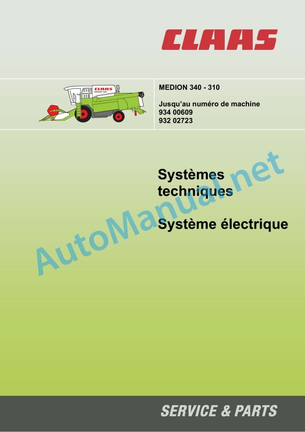
Claas Medion 330-310 (932) Combines Technical System FR
$300.00
- Model: Medion 330-310 (932) Combines
- Type Of Manual: Technical System
- Language: FR
- Format: PDF(s)
- Size: 15.1 MB
File List:
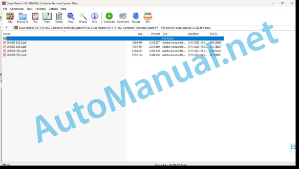
00 0293 825 2.pdf
00 0293 826 2.pdf
00 0298 700 2.pdf
00 0298 705 2.pdf
00 0293 825 2.pdf:
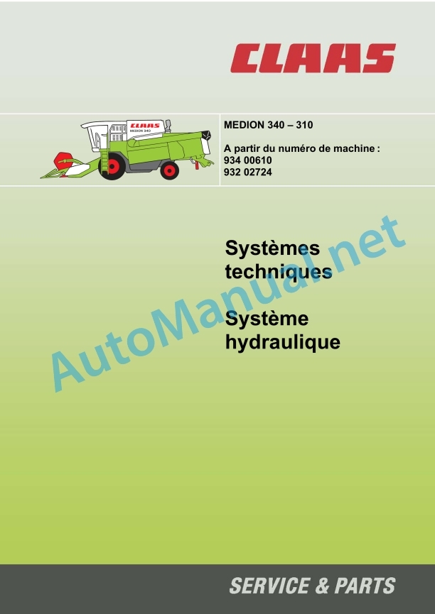
MEDION 340 – 310 from machine number 934 00610, 932 02724 – Technicalsystems, Hydraulic system
Chapter 1 General hydraulics
1.1 General hydraulic system control plan
1.2 Oil tank, oil specification, filling quantity, oil change, oil filter, oil pressure
1.3 Hydraulic pumps
Chapter 2 Steering hydraulics
2.1 Hydraulic steering control plan without AUTOPILOT
2.2 Control plan with AUTOPILOT
2.3 Steering valve block
2.4 Function of neutral steering
2.5 Management check
2.6 AUTOPILOT left/right solenoid valve
2.7 Checking the AUTOPILOT system
Chapter 3 Operating Hydraulics
3.1 Operating hydraulics control plan
3.2 Main valve with cut-off valve, pressure limiter, raising/lowering of the front tool
3.3 Adjusting the mixer rotation speed
3.4 Pivoting the hopper discharge chute
3.5 Inversion of the front tool
3.6 Vertical adjustment of the reel
3.7 Horizontal adjustment of the reel
3.8 Transverse adjustment of the AUTO-CONTOUR cut
Chapter 4 Low pressure hydraulics
4.1 Low pressure hydraulics control plan
4.2 Pressure limiter
4.3 Low pressure hydraulic solenoid valves 3/2 distributor for the mixer clutches, the hopper drain auger and the front tool
4.4 Control of the 3-D cleaning box Pendulum box with 4/3 distributor and hydraulic cylinder
4.5 Front tool drive Hydraulic cylinder with rotating passage
Chapter 5 Front-end tools
5.1 Cut folding control plan
5.2 Control plan for folding the corn header / adjustment of the picking plates
5.3 Folding the 6/2 distributor cup with stop block
5.4 Folding the corn header / adjusting the header plates Valve block
5.5 Rake-up control plan – Hydraulic drive system
Chapter 6 Hydrostatic Drive
6.1 LINDE advancement hydraulics control plan
6.2 Pump unit
6.3 Servo control valve
6.4 Hydrostatic drive multifunction valve
6.5 Constant motor of hydrostatic drive
6.6 4-wheel drive drive
6.7 Maintenance
Chapter 7 Cleaning the Rotary Screen
7.1 Rotary screen control plan
7.2 Rotary screen drive
Keyword index
0293 825.2
00 0293 826 2.pdf:
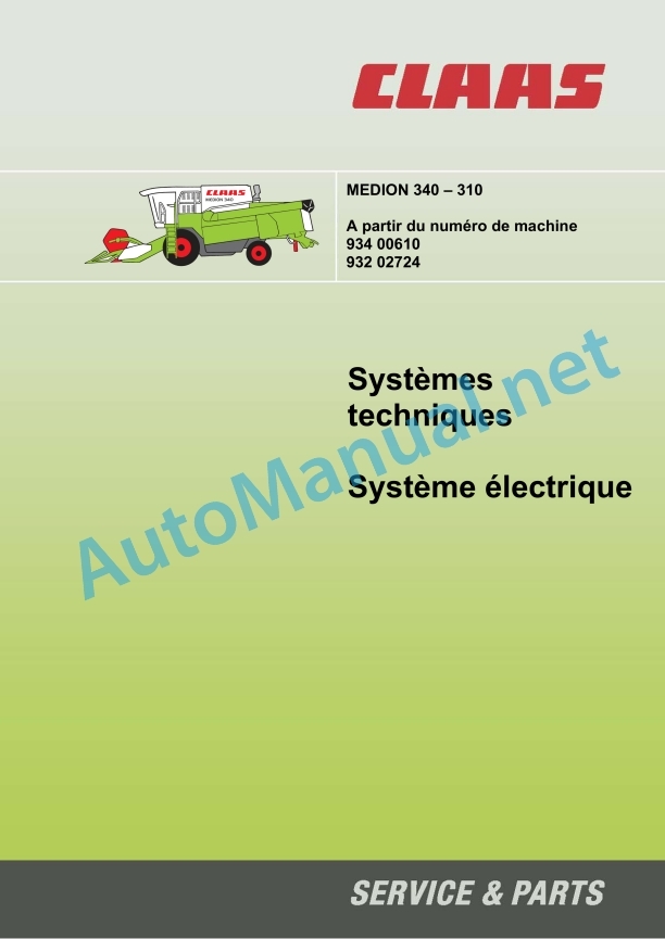
MEDION 340 – 310 From machine number 934 00610, 932 02724. Technical systems, Electrical system
Power plant
Pinout of modules
A6 air conditioning automation module:
A7 cabin fan rotation speed adjustment module:
AUTOCONTOUR module (CAC) A8: ref. 011 015.x
Contour A8 module: ref. 011 026.x
AUTOPILOT A9 module:
A12 rotation speed safety module:
A15 electronic engine control module:
Engine adaptation module (ADM) A17:
Quantity meter module A21:
A26 spreading plate adjustment module:
Multifunction lever module A52:
Overview of fuses:
Electrical plan 01a – 50a
1a Main voltage supply, diesel engine starter
2a Starting the diesel engine, adjusting the rotation speed of the diesel engine
3a Diesel engine safety
4a Road driving control, circuit breaker valve
5a On-board informant
7a Mixer control
8a Beater variator
10a Fan variator
12a Adjustment of the spreading plate, flow control
14a Pivoting of the hopper discharge chute
15a Grain hopper emptying
17a Front tool drive
19a Reel variator
19b Rake-up – Adjustment of rotation speed, hydraulic oil temperature safety
20a Raising / lowering of the front tool, transverse adjustment
21a Adjusting the reel
23a Folding the cup
24a AUTOCONTOUR (CAC)
24b OUTLINE
25a Safety of the rotation regime
26a Machine safety
27a Quantimeter
28a AUTOPILOT
29a 4-wheel drive drive
30a Hopper filling indicator / Rotating beacon
31a Flashing device
32a Main lighting switch, position light
33a Low beam, switching of lights
34a Work lighting
35a Lighting of the grain hopper, the cleaning box, the waste return, reverse warning sound, brake light
36a Interior lighting, instrument lighting
37a Windshield wiper
38a Compressor, cabin fan
38b Air conditioning automation
39a Air seat compressor
40a Additional sockets
50a Electric mirror adjustment
Component coordination scheme
Keyword index
0293 826.2
00 0298 700 2.pdf:
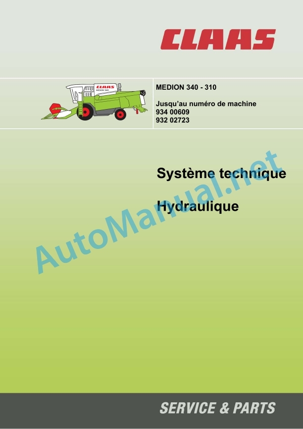
Technical system – Hydraulics MEDION 340 – 310, up to machine number 934 00609, 932 02723
Chapter 1 General hydraulics
1.1 General plan of hydraulic controls – up to machine number 932 02028, 934 00534
1.2 Oil tank, oil specification, filling quantity, oil change, oil filter, oil pressure
1.3 Hydraulic pumps up to machine number 932 02028, 934 00534
Chapter 2 Steering hydraulics
2.1 Hydraulic steering control plan without AUTOPILOT
2.2 Hydraulic steering control plan with AUTOPILOT
2.3 Steering valve block
2.4 Function of neutral steering
2.5 Management check
2.6 AUTOPILOT left/right solenoid valve
2.7 Checking the AUTOPILOT system
Chapter 3 Operating Hydraulics
3.1 Operating hydraulics control plan
3.2 Pressure limiter of the operating hydraulic system
3.3 Raising/lowering the front tool
3.4 Unfolding/folding the grain hopper chute
3.5 Vertical adjustment of the reel
3.6 Inversion of the front tool (hydraulic)
3.7 Transverse adjustment of the AUTO-CONTOUR cut, 4/3 distributor, stop block
3.8 Horizontal adjustment of the reel, 4/3 distributor, stop block
3.9 Adjusting the mixer speed, 3/3 distributor (mechanical)
3.10 Checking the operating hydraulics
Chapter 4 Low pressure hydraulics
4.1 Low pressure hydraulics control plan
4.2 Pressure limiter
4.3 Low pressure hydraulic solenoid valves
4.3 Control of the 3-D cleaning box
4.5 Front tool drive
4.6 Adjusting the rotation speed of the diesel engine (only with Perkins engines)
Chapter 5 Front-end tools
5.1 Cut folding control plan
5.2 Control plan for folding the corn header / adjustment of the picking plates
5.3 Folding the cut
5.4 Folding the corn header / adjusting the header plates
Chapter 6 Hydrostatic Drive
6.1 LINDE advancement hydraulics control plan
6.2 Pump unit
6.3 Servo control valve
6.4 Hydrostatic drive multifunction valve
6.5 Constant motor of hydrostatic drive
6.6 4-wheel drive drive
6.7 Maintenance
Chapter 7 Cleaning the Rotary Screen
7.1 Rotary screen control plan
7.2 Rotary screen drive
Component coordination scheme
Component coordination scheme
Keyword index
0298 700.2
00 0298 705 2.pdf:
Technical systems Electrical system MEDION 340 – 310
Construction of electrical plans
Power plant
Pinout of modules
A6 air conditioning automation module:
Cabin fan rotation speed adjustment module A 7:
AUTOCONTOUR module (CAC) A8: spare parts reference: 011 015.x
Contour A8 module: spare parts reference: 011 026.x
AUTOPILOT A9 module:
A12 rotation speed safety module:
A15 electronic engine control module:
Engine adaptation module (ADM) A17:
Quantity meter module A21:
A26 spreading plate adjustment module:
Order plans 01a – 50a
1a Main voltage supply, diesel engine starter
2a Starting the diesel engine, adjusting the rotation speed of the diesel engine – with mechanical engine adjustment (Perkins)
2b Starting the diesel engine, adjusting the speed of the diesel engine – with electronic engine control (Daimler-Chrysler)
3a Diesel engine safety – with mechanical engine adjustment (Perkins)
3b Diesel engine safety – with electronic engine adjustment (Daimler-Chrysler)
4a Road driving command
5a On-board informant
7a Mixer control up to machine number 932 02028, 934 00534
7b Mixer control from machine number 932 02029, 934 00535
10a Fan variator
12a Adjustment of the spreading plate, flow control
14a Pivoting of the hopper discharge chute
15a Grain hopper emptying
17a Front implement drive, reverse drive (electric)
17b Front attachment drive, reversing drive (hydraulic) up to machine number 932 02028, 934 00534
17c Front attachment drive, reversing drive (hydraulic) from machine number 932 02029, 934 00535
19a Reel variator
20a Raising / lowering of the front tool, transverse adjustment
21a Adjusting the reel
21b Folding the corn header / adjusting the header plates
23a Folding the cup
24a AUTOCONTOUR (CAC)
24b OUTLINE
25a Safety of the rotation regime
26a Machine safety up to machine number 932 02028, 934 00534
26b Machine safety from machine number 932 02029, 934 00535
27a Quantimeter
28a AUTOPILOT
29a 4-wheel drive drive
30a Hopper filling indicator / Rotating beacon
31a Flashing device
32a Main lighting switch, position light
33a Low beam, switching of lights
34a Work lighting up to machine number 932 02028, 934 00534
34b Work lighting from machine number 932 02029, 934 00535
35a Lighting of the grain hopper, the cleaning box, the waste return, reverse warning sound, brake light
36a Interior lighting, instrument lighting
37a Windshield wiper
38a Compressor, cabin fan
38b Air conditioning automation
39a Air seat compressor
40a Additional sockets
50a Electric mirror adjustment
Component coordination scheme
Keyword index
0298 705.2
John Deere Repair Technical Manual PDF
John Deere DF Series 150 and 250 Transmissions (ANALOG) Component Technical Manual CTM147 05JUN98
John Deere Repair Technical Manual PDF
John Deere 16, 18, 20 and 24HP Onan Engines Component Technical Manual CTM2 (19APR90)
John Deere Repair Technical Manual PDF
John Deere Parts Catalog PDF
John Deere Tractors 7500 Parts Catalog CPCQ26568 30 Jan 02 Portuguese
John Deere Repair Technical Manual PDF
John Deere Repair Technical Manual PDF
John Deere Repair Technical Manual PDF
John Deere Application List Component Technical Manual CTM106819 24AUG20
John Deere Repair Technical Manual PDF
John Deere PowerTech M 10.5 L and 12.5 L Diesel Engines COMPONENT TECHNICAL MANUAL CTM100 10MAY11
John Deere Repair Technical Manual PDF
John Deere Diesel Engines POWERTECH 2.9 L Component Technical Manual CTM126 Spanish
John Deere Repair Technical Manual PDF
John Deere Transmission Control Unit Component Technical Manual CTM157 15JUL05

