Claas Mega 350 (835) Combines Technical System EN
$300.00
- Model: Mega 350 (835) Combines
- Type Of Manual: Technical System
- Language: EN
- Format: PDF(s)
- Size: 35.3 MB
File List:
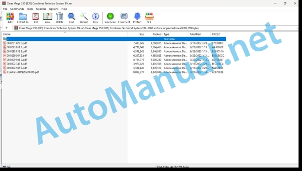
00 0291 027 2.pdf
00 0293 811 2.pdf
00 0293 812 2.pdf
00 0299 504 2.pdf
00 0299 505 2.pdf
00 0302 343 1.pdf
00 0302 565 2.pdf
CLAAS HARNESS PARTS.pdf
00 0291 027 2.pdf:
MB OM460LAMB OM502LAMB OM906LAMB OM926LA
Table of contents
CCN explanation
CCN (CLAAS Component Number)
Electric systems standard
Overview
Hydraulic system standard
Overview
CCN (CLAAS Component Number)
Introduction
Safety rules
Safety and hazard precautions
Validity of manual
Validity of manual
01 Engine
0125 Injection / Fuel system
Injection / fuel system PLD
PLD injection system
Description of function
Pumping phases of plug-on pump
Description of function
Control of plug-on pump
Description of function
Classification of plug-on pumps
Example of a plug-on pump identification plate
Elements in example of plug-on pump identification plate
Fuel low-pressure measurement
Special tool
Preparation of fuel low-pressure measurement
Description of function
Measuring values, fuel low-pressure (downstream of fuel filter)
0155 Engine control
Diesel engine monitoring, diesel engine (MB TIER 3) TUCANO, JAGUAR
Measured values table
Description of function
Diesel engine monitoring, diesel engine (MB TIER 3) LEXION
Measured values table
Description of function
Diesel engine monitoring, diesel engine (MB TIER 4i) TUCANO, JAGUAR
Measured values table
Description of function
Limitation of torque in case of lack of urea
Description of function
Limitation of torque in case of insufficient urea quality
Description of function
Torque limitation after exceeding the time with system faults
Description of function
Diesel engine monitoring, diesel engine (MB TIER 4i) LEXION
Measured values table
Description of function
Limitation of torque in case of lack of urea
Description of function
Limitation of torque in case of insufficient urea quality
Description of function
Torque limitation after exceeding the time with system faults
Description of function
0165 Exhaust gas aftertreatment
Compressed-air system of MB TIER 4i (LEXION, TUCANO)
Description of function
Air dryer with integrated pressure controller
Description of function
Compressed air system MB TIER 4i (JAGUAR)
Description of function
Air dryer with integrated pressure controller
Description of function
SCR system – Urea heating and injection
Description of function
Combined filling level / urea temperature sensor
Description of function
Urea pump unit
Description of function
Reduction catalyst temperature sensors
Description of function
Dosing unit
Description of function
NOx sensor
Description of function
Combined intake air humidity and temperature sensor
Description of function
10 Electrical / Electronic equipment
1012 Modules / sensors
Module overview – MB (OM460LA, 502LA, 906LA, 926LA)
Key to diagram
Module A015 – Electronic engine control (ECM) – MB TIER 4i
Connector X1
Key to diagram
Module pin assignment, connector X1
Connector X2, sheet 1 of 2, 6-cylinder inline and V8 engine
Module pin assignment, connector X2 sheet 1 of 2
Connector X2, sheet 2 of 2, 6-cylinder inline engine
Module pin assignment, connector X2 sheet 2 of 2, 6-cylinder inline engine
Connector X2, sheet 2 of 2, V8 engine
Module pin assignment, connector X2 sheet 2 of 2, V8 engine
Module A017 – Engine adaptation module (ADM) – MB TIER 3
Key to diagram
Key to diagram
Module A017 – Engine adaptation module (ADM) – MB TIER 4i
Key to diagram
Key to diagram
Module A032 – Reduction catalyst (SCR) – MB TIER4i
Key to diagram
Key to diagram
Sensors MB OM460LA
Figure of sensors
Sensors on MB 502LA
Figure of sensors
Sensors on MB OM 906LA, OM 926LA
Figure of sensors
1085 Networks
BUS system (CAN) – engine and machine
Description of function
92 Diagnosis
Diagnosis by fault codes
9220 Error codes engine (J1939)
FMI failure code (Failure Mode Indicator)
FMI failure code (Failure Mode Indicator)
FMI 00 (Signal too high)
FMI 01 (Signal too low)
FMI 02 (Erratic signal)
FMI 03 (Voltage too high)
FMI 04 (Voltage too low)
FMI 05 (Current too low)
FMI 06 (Current too high)
FMI 07 (Mechanical failure)
FMI 08 (Abnormal frequency signal)
FMI 09 (Communication error)
FMI 10 (Rate of signal change too fast)
FMI 11 (multiple faults)
FMI 12 (ECU defective)
FMI 13 (Signal outside of calibration range)
FMI 16 (Parameter not available)
FMI 17 (ECU not responding)
FMI 18 (Power supply failure)
FMI 19 (Software conditions not met)
FMI 95 (no signal change)
FMI 96 (CAN Bus system defective)
FMI 97 (Erratic condition)
FMI 98 (Warning)
FMI 99 (Info)
Fault codes
Diesel engine J1939 (MB) fault code list
Description of function
00 0293 811 2.pdf:
MEGA 370 – 350 From serial number: 845 00387, 835 00361 – Technical Systems, Hydraulic System
Table of Contents
Chapter 1 Overall hydraulic system
1.1 Overall hydraulic system circuit diagram
1.2 Oil tank, oil specification, filling quantities, oil change, oil filter, oil pressure
1.3 Hydraulic pumps
Chapter 2 Steering hydraulics
2.1 Steering hydraulics circuit diagram without AUTOPILOT
2.2 Steering hydraulics circuit diagram with AUTOPILOT
2.3 Steering valve unit
2.4 Function of steering – neutral
2.5 Checking the steering
2.6 AUTOPILOT left/right solenoid valve
2.7 Checking the AUTOPILOT System
Chapter 3 Working hydraulics
3.1 Working hydraulics circuit diagram
3.2 Main Valve with master valve, pressure relief valve, raise/lower front attachment
3.3 Threshing Drum Speed Control
3.4 Swing Grain Tank Unloading Tube
3.5 Reverse Front Attachment
3.6 Vertical Reel Adjustment
3.7 Horizontal Reel Adjustment
3.8 AUTO-CONTOUR cutterbar transverse control
Chapter 4 Low-pressure hydraulic circuit
4.1 Low-pressure hydraulic circuit diagram
4.2 Pressure relief valve
4.3 Low-pressure hydraulic circuit solenoid valves Threshing mechanism clutch, grain tank unloading, front attachment clutch 3/2 way valves
4.4 3-D cleaning system Pendulum housing with 4/3 way valve and hydraulic cylinder
4.5 Front attachment drive Hydraulic cylinder with rotary coupling
Chapter 5 Front attachments
5.1 Cutterbar fold circuit diagram
5.2 Maize picker fold / Snapping plate adjustment circuit diagram
5.3 Folding the cutterbar 6/2 way solenoid valve with lock-up valve unit
5.4 Folding the maize picker / Snapping plate adjustment Valve unit
5.5 Rake-up circuit diagram – Drive hydraulics
Chapter 6 Ground drive hydraulics
6.1 LINDE ground drive hydraulics circuit diagram
6.2 Pump unit
6.3 Servo adjustment valve
6.4 Ground drive multi-function valve
6.5 Ground drive fixed displacement motor
6.6 4-Trac drive
6.7 Maintenance
Chapter 7 Rotary chaff screen cleaning
7.1 Rotary chaff screen circuit diagram
7.2 Rotary chaff screen drive
0293 811.2
00 0293 812 2.pdf:
MEGA 370 – 350 From serial number: 845 00387, 835 00361 – Technical Systems, Electric System
CONTENTS
Central terminal compartment
Pin assignment in modules
Automatic air conditioner module A6:
Cab fan speed controller module A7:
Contour module (CAC) A8: Spare part no. 011 015.x
Contour module A8: Spare part no. 011 026.x
AUTOPILOT module A9:
Speed monitor module A12:
Electronic engine control module A15:
Engine adaptation module (ADM) A17:
Yield meter module A21:
Deflector adjustment module A26:
Multifunction handle module A52:
Overview of fuses:
Circuit diagrams 01a – 50a
1a Main power supply, Diesel engine electric starting motor
2a Starting the diesel engine, diesel engine speed adjustment
3a Diesel engine cut-off system
4a Activation of road travel, master valve
5a Fieldwork computer
7a Threshing mechanism circuit
8a Threshing drum variable-speed drive
10a Fan variable-speed drive
12a Deflector adjustment, performance monitor
14a Swinging the grain tank unloading tube
15a Grain tank unloading
17a Front attachment drive
19a Reel variable-speed drive
19b Rake-up – Speed adjustment, hydraulic oil temperature monitoring
20a Front attachment raise/lower, transverse control
21a Reel adjustment
23a Folding the cutterbar
24a AUTOCONTOUR (CAC)
24b CONTOUR
25a Speed monitoring
26a Machine monitoring
27a Yield meter
28a AUTOPILOT
29a All-wheel drive
30a Grain tank full indicator / warning beacon
31a Turn flasher system
32a Main light circuit, position light
33a Dipped headlights, dipped headlights changeover
34a Work lights
35a Grain tank, sieve pan and returns lighting, reversing horn, brake light
36a Interior lights, instrument lighting
37a Windscreen wiper
38a Compressor-type air conditioner, cab fan
38b Automatic air conditioner
39a Air-suspended seat compressor
40a Additional sockets
50a Electric mirror adjustment
Component grid
0293 812.2
00 0299 504 2.pdf:
Technical Systems – Hydraulic System MEGA 360 – 350, up to serial number: 845 00386, 835 00360
Table of Contents
Chapter 1 Overall hydraulic system
1.1 Overall hydraulic system circuit diagram
1.2 Oil tank, oil specification, filling quantities, oil change, oil filter, oil pressure
1.3 Hydraulic pumps
Chapter 2 Steering hydraulics
2.1 Steering hydraulics circuit diagram without AUTOPILOT
2.2 Steering hydraulics circuit diagram with AUTOPILOT
2.3 Steering valve unit
2.4 Function of steering – neutral
2.5 Checking the steering
2.6 AUTOPILOT left/right solenoid valve
2.7 Checking the AUTOPILOT System
Chapter 3 Working hydraulics
3.1 Working hydraulics circuit diagram
3.2 Working hydraulics pressure relief valve
3.3 Front attachment raise/lower
3.4 Swing grain tank unloading tube in/out
3.5 Vertical reel adjustment
3.6 Reversing the front attachment (hydraulic)
3.7 AUTO-CONTOUR cutterbar transverse control
3.8 Hydraulic fore and aft reel adjustment
3.9 Threshing drum speed adjustment
3.10 Checking the working hydraulics
Chapter 4 Low-pressure hydraulic circuit
4.1 Low-pressure hydraulic circuit diagram
4.2 Pressure relief valve
4.3 Low-pressure hydraulic circuit solenoid valves
4.4 3-D cleaning system
4.5 Front attachment drive
Chapter 5 Front attachments
5.1 Cutterbar fold circuit diagram
5.2 Maize picker fold / Snapping plate adjustment circuit diagram
5.3 Folding the cutterbar
5.4 Folding the maize picker / Snapping plate adjustment
Chapter 6 Ground drive hydraulics
6.1 LINDE ground drive hydraulics circuit diagram
6.2 Pump unit HPV 105
6.3 Servo adjustment valve
6.4 Ground drive multi-function valve
6.5 Ground drive fixed displacement motor Motor unit HMF 105
6.6 4-Trac drive Valve unit
6.7 Maintenance
Chapter 7 Rotary chaff screen cleaning
7.1 Rotary chaff screen circuit diagram
7.2 Rotary chaff screen drive
Position of components
Component grid
0299 504.2
00 0299 505 2.pdf:
Technical Systems Electric System Mega 360 – 350
Layout of electric circuit diagrams
Contents
Central terminal compartment
Pin assignment in modules
Automatic air conditioner module A6:
Cab fan speed controller module A7:
AUTOCONTOUR module (CAC) A8: Spare part no. 011 015.x
Contour module A8: Spare part no. 011 026.x
AUTOPILOT module A9:
Speed monitor module A12:
Electronic engine control module A15:
Engine adaptation module (ADM) A17:
Yield meter module A21:
Deflector adjustment module A26:
Circuit diagrams 01a – 50a
1a Main power supply, Diesel engine electric starting motor
2a Starting the diesel engine, diesel engine speed adjustment
3a Diesel engine cut-off system
4a Activation of road travel
5a Fieldwork computer
7a Threshing mechanism circuit up to serial no. 835 00146, 845 00123
7b Threshing mechanism circuit from serial no. 835 00147, 845 00124
10a Fan variable-speed drive
12a Deflector adjustment, performance monitor
14a Swinging the grain tank unloading tube
15a Grain tank unloading
17a Front attachment drive, reverser drive (electric)
17b Front attachment drive, reverser drive (hydraulic) up to serial no. 835 00146, 845 00123
17c Front attachment drive, Reverser drive (hydraulic) from serial no. 835 00147, 845 00124
19a Reel variable-speed drive
20a Front attachment raise/lower, transverse control
21a Reel adjustment
21b Folding the maize picker / snapping plate adjustment
23a Folding the cutterbar
24a AUTOCONTOUR (CAC)
24b CONTOUR
25a Speed monitoring
26a Machine monitoring up to serial no. 835 00146, 845 00123
26b Machine monitoring from serial no. 835 00147, 845 00124
27a Yield meter
28a AUTOPILOT
29a All-wheel drive
30a Grain tank full indicator / warning beacon
31a Turn flasher system
32a Main light circuit, position light
33a Dipped headlights, dipped headlights changeover
34a Work lights up to serial no. 835 00146, 845 00123
34b Work lights from serial no. 835 00147 845 00124
35a Grain tank, sieve pan and returns lighting, reversing horn, brake light
36a Interior lights, instrument lighting
37a Windscreen wiper
38a Compressor-type air conditioner, cab fan
38b Automatic air conditioner
39a Air-suspended seat compressor
40a Additional sockets
50a Electric mirror adjustment
Component grid
0299 505.2
00 0302 343 1.pdf:
PROFI CAM 3
Table of contents
General information
Marking of warnings and hazard prevention notes
First-aid measures
CCN explanation
CCN (CLAAS Component Number)
Electric system standard
Overview
Hydraulic system standard
Overview
CCN (CLAAS Component Number)
10 Electrical / Electronic equipment
1030 Board computer / Indicators
Camera system
Description of function
1097 Testing / Measuring / Adjusting
Testing / measuring / adjusting the PROFI CAM
Checking the fuse in the video channel select box (C102)
Testing the video camera connector (C055)
1098 Fault / remedy
Fault / remedy PROFI CAM
The video monitor (C101) shows no image or cannot be switched on (indicator light fails to light up)
Video monitor (C102) displays a blue image either permanently or temporarily
The video monitor image is blurred
Replacing the fuse in the video channel select box (C102)
Connection and connecting cable with video camera (C055)
00 0302 565 2.pdf:
Sensor system
Table of contents
CCN explanation
CCN (CLAAS Component Number)
Electric system standard
Overview
Hydraulic system standard
Overview
CCN (CLAAS Component Number)
Introduction
Safety rules
Safety and hazard information
10 Electrical / Electronic equipment
1097 Testing / Measuring / Adjusting
Test report of the angle sensor (0011780.x)
Application of test report
Required tools
Test report of the angle sensor (0011780.x)
Testing / Measuring / Adjusting of angle sensor (0011780.x)
1. Reason for test
2. Mechanical test of angle sensor
3. Electric test with CDS
4. Electric test with multimeter
5. Mechanical test of connecting cable
Completing the machine
Test report of position and speed sensors
Application of test report
Required tools
Sensor variants
Part numbers of speed sensors
Part number of position sensor
Test report of position and speed sensors
Testing / measuring / adjusting of position and speed sensors
1. Reason for test
2. Mechanical test
3. Electric test with CDS
4a. Installation dimensions
Check of installation dimension
Installation dimensions of gearbox speed sensor (0011 799.x) and cam speed sensor (0011 810.x)
Installation dimension of position sensor (0011 815.x)
4b. Installation position
Centring of sensor
Metal-free zone
5. Electric test with multimeter
Voltage measurement
Direction of rotation and speed sensor (0011 605.x)
Measured values table
6. Mechanical test of connecting cable
Completing the machine
Test report of the urea sensor (00 0773 207 x)
Application of test report
Required tools
Parts number of the urea sensor
Test report of the urea sensor
Testing / measuring / adjusting urea sensor
1. Reason for test
2. Mechanical test
3. Mechanical test of connecting cable
4. Electric test with multimeter
5. Component test with the CDS
CLAAS HARNESS PARTS.pdf:
CLAAS HARNESS PARTS
Table of contents
10 Electrical / Electronic equipment
1081 Overview of connectors
CLAAS HARNESS PARTS (CHP)
John Deere Repair Technical Manual PDF
John Deere Repair Technical Manual PDF
John Deere Repair Technical Manual PDF
John Deere Repair Technical Manual PDF
John Deere Repair Technical Manual PDF
John Deere PowerTech M 10.5 L and 12.5 L Diesel Engines COMPONENT TECHNICAL MANUAL CTM100 10MAY11
John Deere Repair Technical Manual PDF
John Deere Parts Catalog PDF
John Deere Tractors 7500 Parts Catalog CPCQ26568 30 Jan 02 Portuguese
John Deere Repair Technical Manual PDF
John Deere Repair Technical Manual PDF

