Claas Miscellaneous Repair Manual EN
$100.00
- Model: Miscellaneous
- Type Of Manual: Repair Manual
- Language: EN
- Format: PDF(s)
- Size: 61.7 MB
File List:
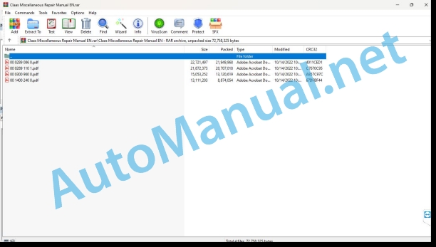
00 0289 086 0.pdf
00 0289 110 1.pdf
00 0300 960 0.pdf
00 1400 240 0.pdf
00 0289 086 0.pdf:
CTIC 2800CTIC
Table of contents
Introduction
General information
Validity of manual
Handling of this manual
General repair instructions
Technical specifications
Information on technically correct repairs
Self-locking bolts
Liquid locking compound
Circlips
Hydraulic hoses
Hose routing
Spare parts and technical questions
Tightening torques
Tightening torques for metric ISO screw thread
Tightening torques for metric fine thread
General information
Particularly important
Qualification of drivers and maintenance personnel
Identification of warning and danger signs
General safety and accident prevention regulations
Pressurised fluids
Pressure accumulator
Putting the machine out of operation
Raised machine parts and loads
No welding
Optional equipment and spare parts
Tyre pressure control system
Overview
Electronic box
Control valve block
Rotary coupling
Compressor
Compressor
Oil cooler
Hydraulic motor
Hydraulic motor
Flow control valve
Flow control valve
Flow control valve
Appendix
Tyre pressure control system
Circuit diagrams
00 0289 110 1.pdf:
CTIC 2800 2.0CTIC 2.0CTIC TI 2.0
Table of contents
Introduction
General information
Validity of manual
Handling of this manual
General repair instructions
Technical specifications
Information on technically correct repairs
Self-locking bolts
Liquid locking compound
Circlips
Hydraulic hoses
Hose placement
Spare parts and technical questions
Tightening torques
Tightening torques for metric ISO screw threads
Tightening torques for metric fine thread screws
Tightening torques for hydraulic fittings with ferrule
Tightening torques for pipe fittings with sealing cone joints and hydraulic fittings with soft ring seals
Tightening torques for hydraulic male connectors SDS shape B and E
Tightening torques for SDS shape F hydraulic male connectors
Tightening torques for hydraulic male connectors SDE shape H, with adjustable direction
General information
Particularly important
Qualification of drivers and maintenance personnel
Identification of warning and danger signs
General safety and accident prevention regulations
Pressurised fluids
Pressure accumulator
Putting the machine out of operation
Raised machine parts and loads
No welding
Optional equipment and spare parts
Tyre pressure control system
CTIC 2800 2.0 / CTIC 2.0
Overview
Overview
Compressor unit
Removing the cap
Removing the compressor unit
Installing the compressor unit
Installing the cap
Control unit
Removing the cap
Removing the control unit
Installing the control unit
Installing the cap
Rotary transmission leadthrough
Work preparation
Removing
Disassembling the rotary transmission leadthrough
Disassembling the rotor
Disassembling the stator
Assembling the stator
Assembling the rotor
Assembling the rotary transmission leadthrough
Installing
Control units
Removing
Installing
Control units
Removing
Installing
Control valve block
Work preparation
Removing
Disassembling
Assembling
Installing
Control valve block
Work preparation
Removing
Disassembling
Assembling
Installing
Hydraulic valve block
Work preparation
Removing
Disassembling
Assembling
Installing
Hydraulic motor
Work preparation
Removing
Removing the radial shaft seal
Installing the radial shaft seal
Installing
Oil cooler
Work preparation
Removing
Installing
Compressor
Work preparation
Removing
Removing the baffle plate
Disassembling and assembling
Installing the baffle plate
Installing
CTIC TI 2.0 control valve block
Work preparation
Removing
Disassembling
Assembling
Installing
CTIC TI 2.0 tyre pressure valve block
Work preparation
Removing
Disassembling
Assembling
Installing
00 0300 960 0.pdf:
DOMINATOR 40 TERRA TRAC
Table of contents
Introduction
General information
Handling the manual
Texts and figures
Document structure based on the assembly structure
Search and find
Directions
Abbreviations
Technical terms
Validity of manual
General repair instructions
Technical specifications
Reason of damage
Spare parts
Alternator
Welding work
Drive belts / drive chains
Taper ring fasteners
Gib head key joints
Dismounting
Installation
Self-locking bolts
Liquid locking compound
Lock collar bearing
Dismounting
Installation
Adapter sleeve bearings
Dismounting
Installation
Ferrule fittings
Screwing in
Non-tight ferrule connection
Progressive ring fittings on hydraulic lines
Sealing cone fittings
Hydraulic hoses
Information on proper repairs
Torque settings
Tightening torques for metric standard threads
Tightening torques for metric fine thread screws
Tightening torques for hydraulic screw fittings with ferrule according to DIN 3861
Tightening torques for hydraulic screw fittings and air conditioner screw fittings with sealing cone and O-ring according to DIN 3865
Tightening torques for SDS hydraulic male connectors
Tightening torques for direction-adjustable SDE hydraulic male connectors
Tightening torques for hydraulic swivel fittings
Tightening torques for hollow screws DIN 7643
Tightening torques for worm drive hose clamps
Tightening torque for spring-loaded worm drive hose clamps
Technical specification
Lubricants
General information
Of special importance
Identification of warning and danger signs
General safety and accident prevention regulations
Combine-harvester safety and accident prevention regulations
Crop / straw discharge
Leaving the machine
Grain tank
Combine harvester chopper
Adjustment and maintenance operations
Risk of injury by hydraulic liquid
Hydraulic accumulators
First aid measures
Battery isolating switch
Apply the feeder housing safety lock
Jacking up the machine
Putting the machine out of operation
01 Engine
0102 Complete component
Diesel engine
Work preparation
Special tools
Removal of diesel engine
Removal of side flap
Tensioning device
Tensioner belt
Hydraulic hoses
Electric system
Starter relay
Alternator
EGR valve
Acclerator rod
Diesel pipe
Air pump
Air reservoir
Water separator
Torque fittings
Installation
Work Preparation:
Diesel engine:
Water separator
Air reservoir
Air pump
Diesel pipe
Accelerator rod:
Electric system
EGR valve
Alternator
Starter relay
Hydraulic hoses
Tensioner belt
Tensioning device
Finalization:
0125 Fuel system
Fuel tank
Work preparation
Special tool
Removal of fuel tank
Electric system
Fuel supply
Installation of fuel tank
Fuel supply
Electric system
Strap clamps
Finalization
0135 Cooling system
Cooling system
Work preparation
Removal of oil cooler
Air flow pipe
Radiator
Coolant reservoir
Covering
Note: Before removing the radiator:
Installation
Radiator
Covering
Air flow pipe
Coolant reservoir
Oil cooler
Finalization
0140 Exhaust system
Silencer
Work preparation
Removal of silencer
Installation of silencer
Finalization
0145 Air intake
Air intake
Removal of air intake:
Installation of air intake
Finalization
0150 Engine Attachment parts
Engine attachment parts
Before removal
Removal of engine attachment parts
Starter relay
Alternator
EGR valve
Installation engine attachment parts
EGR valve
Alternator
Starter relay
Finalization
02 Gearbox / Clutch / Universal drive shaft
0210 Oscillation damper
Complete gearbox:
Work preparation
Before removal
Removal of hydraulic gear box
Installation of Hydraulic gearbox
Finalization:
Engine output
Work preparation
Special tool
Removal of engine output pulley
Installation of engine output pulley
Removing the oscillation damper
Installation of oscillation damper
Finalization
03 Chassis
0355 Track roller unit
Crawler track unit
Work preparation
Special tool
Removal of rubber track
Guide wheel
Support wheel
Rubber track
Driving gear
Installation of rubber track:
Driving gear
Rubber track
Support wheel
Guide wheel
Finalization
08 Drives
0800 Drives
0808 Main drive
Engine output
Work preparation
Special tool
Work preparation
Removal of engine output pulley
Installation of engine output pulley
Finalization
Belt (R1)
Special tool
Special tool
Work preparation
Removal of Impeller drive:
Driven pulley:
Installation of Impeller drive
Driven pulley:
Finalization
0820 Front attachment drive
Chain (R4)
Special tool
Work preparation
Removal of the driven Sprocket:
Installation of the driven sprocket
Finalization
Chain (K7)
Work preparation
Removal of the Reel sprocket:
Installation of the reel sprocket
Finalization
Belt (R3)
Special tool
Work preparation
Removal of cutter bar drive
Drive pulley:
Installation of cutter bar drive
Drive pulley:
Finalization
0841Threshing drum drive
Belt (R10)
Work preparation
Before removal
Removal of threshing drum drive
Installation of threshing drum drive
Finalization
0821 Feeder unit drive
Belt (R2)
Special tool
Work preparation
Removal of feeder drive
Drive pulley:
Driven pulley:
Installation of feeder drive
Driven pulley:
Drive pulley:
Finalization
0842 Separation drive
Belt (R12)
Special tool
Work preparation
Removal of seperation drives:
Straw walker drive pulley:
Installation of separation drives
Straw walker drive pulley
Finalization
0860 Cleaning system drive
Belt (R11)
Work preparation
Before removal
Removal of cleaning system drive
Sieve box pulley
Fan pulley
Installation of cleaning system drive
Fan pulley
Sieve box pulley
Finalization
0861 Grain delivery drive
Chain (K13)
Work preparation
Removal of return elevator auger drive:
Drive sprocket:
Driven sprocket:
Installation of return elevator auger drive
Driven sprocket
Drive sprocket:
Finalization
Chain (K14)
Special tool
Work preparation
Removal of grain tank unloading drive
Drive sprocket:
Grain tank unloading sprocket:
Installation of grain tank unloading drive
Grain tank unloading sprocket
Drive sprocket:
Finalization
Belt (R12)
Special tool
Work preparation
Removal of clean grain auger drive
Grain auger drive pulley
Installation of clean grain auger drive
Grain auger drive pulley
Finalization
Belt (R9)
Special tool
Work preparation
Removal of return drive
Driven pulley:
Drive pulley:
Installation of return drive
Drive pulley
Driven pulley:
Finalization
09 Hydraulic system
0905 Hydraulic oil reservoir
0907 Hydraulic oil cooler
Hydraulic oil cooler
Work preparation
Removal of hydraulic oil cooler
Installation of hydraulic oil cooler
Finalization
0910 Pumps
Hydraulic pump:
Work preparation
Removal of hydraulic pump
Installation of hydraulic pump
Hydraulic hoses
Finalization
0920 Main valve
Main valve
Work preparation
Removal of main valve
Installation of main valve
Finalization
10 Electrical / Electronic equipment
1010 Central electrics
Central terminal compartment
Work preparation
Removal of Operating console
Installation of operating console
Finalization
1020 Driving lights
Driving lights:
Work preparation
Removal of driving lights(R2)
Installation of driving lights(R2)
Finalization
1025 Working lights
Working lights:
Work preparation
Removal of working light
Installation of working light
Finalization
1035 Operation / Multifunction lever
Control lever:
Work preparation
Removal of control lever
Installation of control lever
Removal of Battery
Installation of battery
Finalization
12 Cab / Operator’s platform
1215 Operator’s platform
Before removal
Removal of Sun roof
Installation of Sun roof
Operating console
Before removal
Removal of Operating console
Installation of operating console
Finalization:
1225 Mirror
Removal of mirror
Installation of mirror
1230 Seat
Removal of seat
Installation of seat
20 Crop feeding
2015 Cutter bar
Reel drive
Removal of reel drive
Work preparation:
Installation of reel drive
Removal of tine spring
Installation of tine spring
Finalization
21 Feeder unit
2110 Feed rake
Feeder Unit
Dominator 40 Terra Trac
Removal of front attachment
Removal of feed rake conveyer:
Installation of feed rake conveyor
Installation of front attachment
Finalization
23 Mower unit
2300 Mower unit
Mower unit
Work preparation
Special tool
Removal of mow blade
Installation of mow blade
Finalization
41 Threshing mechanism
4120 Threshing drum
Threshing drum
Work preparation
Before removal of Threshing drum
Special tool
Removal of threshing drum
Installation of threshing drum
Gap setting between concave pin and drum pin:
Finalization
4125 Threshing concave
Threshing concave
Work preparation
Removal of threshing concave
Installation of threshing concave
Adjusting the distance of threshing concave
Finalization
42 Separation
4210 Separation
Straw walkers
Work preparation
Removal of straw walker racks
Installation of straw walker racks
Wooden bearing
Finalization
Removal of front straw walker crankshaft
Installation of front straw walker crankshaft
Removing the rear straw walker crankshaft
Installing the Rear straw walker crankshaft
Finalization
43 Cleaning system
4320 Sieves / Sieve pan
Sieve pan
Work preparation
Removal of sieve pans
Installation of sieve pans
Finalization
4325 Cleaning fan
Cleaning fan
Work preparation
Removal of cleaning fan
Fan pulley
Installation of cleaning fan
Fan pulley
Finalization
61 Grain delivery
6115 Grain tank filling
Return elevator
Work preparation
Special tool
Removal of lock collar bearing
Installation of lock collar bearing
Removal of conveyor plate
Installation of Conveyor plate
Chain tension
Finalization
Grain elevator
Work preparation
Special tool
Removal of lock collar bearing
Installation of lock collar bearing
Removal of Conveyor plate
Installation of Conveyor plate
Chain tension
Finalization
6120 Grain tank unloading tube
Grain tank unloading tube
Work preparation
Removal of unloading tube
Greasing
Installation of unloading tube
Finalization
80 Various components / Machine body
8025 Panellings / Hoods
Left side flaps
Work preparation
Removal of left side front flap
Installation of left side front flap
Removal of left side rear flap
Installation of left side rear flap
Finalization
Right side flaps:
Work preparation
Removal of right side front flap
Installation of right side front flap
Removal of right side rear flap
Installation of right side rear flap
Removal of radiator screen
Installation of radiator screen
Finalization
Front attachment panels
Work preparation
Removal of front attachment upper guard
Installation of front attachment upper guard
Removal of front attachment lower guard
Installation of front attachment lower guard
Finalization
00 1400 240 0.pdf:
CULTI CAM
Table of contents
1 To this operator’s manual
1.1 Notes on the manual
1.1.1 General instructions
1.1.2 Validity of manual
1.1.3 Handling of manual
1.1.4 Symbols and notes
1.1.5 Equipment
1.1.6 Technical specifications
2 Safety
2.1 Safety rules
2.1.1 Particularly important
2.1.2 Qualification of drivers and maintenance personnel
2.1.3 Intended use
2.1.4 General safety and accident prevention regulations
2.1.5 Hydraulic accumulators
2.1.6 First aid measures
2.1.7 Danger of injury due to hydraulic liquid
2.2 Safety instructions in this manual
2.2.1 Identification of warning and danger signs
2.3 Safety devices
2.3.1 Safety instructions for starting the terminal
3 Product description
3.1 Overview and method of operation
3.1.1 Overview of CULTI CAM
3.1.2 Overview of COMMUNICATOR II
Backward compatibility
3.1.3 Overview of camera
3.1.4 Overview of UBM module
3.1.5 Overview of sensors
Working position switch
Travel speed sensor
Steering angle sensor
3.1.6 Overview of hydraulic system
3.1.7 Overview of cables
Main wiring loom
Tractor wiring loom
Camera connecting cable
3.1.8 Function of CULTI CAM
Visual principle
3.1.9 Possible applications and pre-conditions
Pre-conditions for row of plants
Pre-conditions for multiple row
3.1.10 Accuracy and signal quality
Accuracy
Signal quality
Hilly terrain
Moisture
3.1.11 Plant pre-conditions
Green salad
Cauliflower
Broccoli
Witloof chicory
Strawberries
Tomatoes
Sugar beets
3.2 Optional equipment
3.2.1 Optional machine equipment
3.2.2 Video monitor
Function
Invalid signal
Valid signal
3.2.3 Xenon light
3.2.4 Extension cable
3.2.5 Bracket
Aluminium section bracket
Aluminium section
Connector bracket
3.3 Identification plates and identification number
3.3.1 Spare parts and technical questions
3.3.2 Position of identification plate
3.3.3 Explanation of camera identification plate
3.3.4 Explanation of COMMUNICATOR II identification plate
3.3.5 Explanation of UBM module identification plate
4 Operating and control elements
4.1 COMMUNICATOR II
4.1.1 Terminal
4.1.2 Terminal program
4.1.3 Main menu – “Information”
4.1.4 Main menu – “Settings”
4.1.5 Main menu – “Terminal settings”
4.2 CULTI C CULTI CAM application
4.2.2 Menu cards
4.2.3 Automatic control menu card
4.2.4 Application settings menu card
4.2.5 General settings menu card
4.2.6 Extended settings menu2.7 Information menu card
5 Technical specifications
5.1 COMMUNICATOR II
5.1.1 Specification
5.2 CULTI CAM
5.2.1 Specification
5.2.2 Software version
6 Preparing the product
6.1 General Information
6.1.1 General warnings
6.1.2 Turning off and securing the machine
6.2 Prior to operation
6.2.1 Before commissioning
6.2.2 Every time before putting into operation
6.3 Mounting
6.3.1 Camera
6.3.2 Adjusting the camera position
Adjusting the camera height
Camera height setting values
Plant row and multiple row
Detecting the camera height
Adjusting the camera angle
Detecting the camera angle
6.3.3 Operation and output
COMMUNICATOR II
6.3.4 Electronics
UBM module
6.3.5 Hydraulic system
6.3.6 Xenon light
6.4 CULTI CAM
6.4.1 Preparing calibration
6.4.2 Perform calibration
Calibration of travel speed sensor
Entering the value manually
Testing the control unit
Alternative:
Calibration of steering angle sensor
Calibration of maximum deflection
Adjusting the steering rate
Sensitivity
Setting the threshold value
Calibration of camera
Performing the camera calibration
6.4.3 Extended calibration
Factory settings
Alarm delay
Simulation speed
Inverting the position switch
Automatic centring
Twin-camera mode
7 Operation
7.1 Driving on the road
7.1.1 Road travel
7.2 Switching COMMUNICATOR II on/off
7.2.1 Engaging COMMUNICATOR II
7.2.2 Selecting an application
7.2.3 Switching COMMUNICATOR II off
7.3 Programmable COMMUNICATOR II keys
7.3.1 Key assignment
7.4 COMMUNICATOR II ISOBUS settings
7.4.1 Administration of applications
7.5 COMMUNICATOR II terminal settings
7.5.1 Setting the screen brightness/volume
7.5.2 Setting the language
7.5.3 Setting the display formats
7.5.4 Setting the date/time
7.5.5 Displaying the COMMUNICATOR II software version
7.6 Fieldwork
7.6.1 General settings
Xenon light
Dual offset
7.6.2 Setting an application
Row of plants
Multiple row
7.6.3 Automatic control
Activating automatic control
Deactivating automatic control
Side shifting
Dual offset
Xenon light
8 Faults and remedies
8.1 Overview of faults
8.1.1 CULTI CAM fault table
Hydraulic system fault
8.1.2 Questions and answers
9 Maintenance
9.1 General Information
9.1.1 General warnings
9.2 Maintenance Information
9.2.1 Maintenance intervals
10 Service
10.1 General Information
10.1.1 Spare parts and technical questions
10.1.2 Service and warranty
Warranty handling
11 Placing out of operation and disposal
11.1 General Information
11.1.1 Putting out of operation and disposal
12 Technical terms and abbreviations
12.1 Terms and explanations
12.1.1 Units
12.1.2 Abbreviations
12.1.3 Technical terms
John Deere Repair Technical Manual PDF
John Deere 16, 18, 20 and 24HP Onan Engines Component Technical Manual CTM2 (19APR90)
John Deere Repair Technical Manual PDF
John Deere DF Series 150 and 250 Transmissions (ANALOG) Component Technical Manual CTM147 05JUN98
John Deere Repair Technical Manual PDF
John Deere Repair Technical Manual PDF
John Deere Diesel Engines POWERTECH 2.9 L Component Technical Manual CTM126 Spanish
John Deere Repair Technical Manual PDF
John Deere Repair Technical Manual PDF
John Deere Repair Technical Manual PDF
John Deere Repair Technical Manual PDF
John Deere PowerTech M 10.5 L and 12.5 L Diesel Engines COMPONENT TECHNICAL MANUAL CTM100 10MAY11

