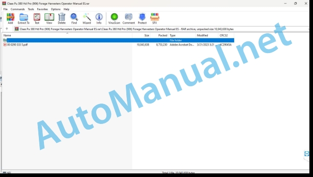
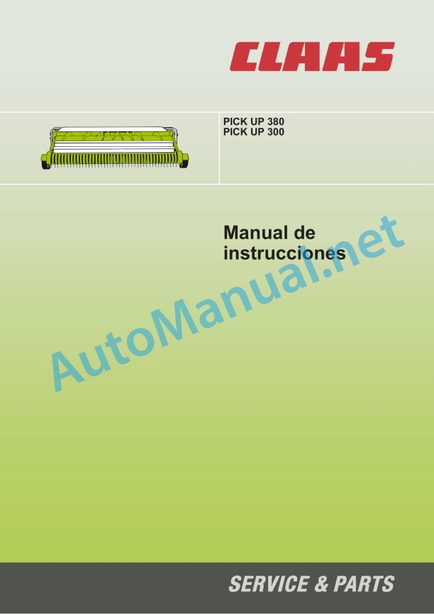
Claas Pu 380 Hd Pro (906) Forage Harvesters Operator Manual ES
$50.00
- Model: Pu 380 Hd Pro (906) Forage Harvesters
- Type Of Manual: Operator Manual
- Language: ES
- Format: PDF(s)
- Size: 8.3 MB
File List:
00 0290 333 5.pdf
00 0290 333 5.pdf:
PICK UP 380PICK UP 300
1 Regarding this instruction manual
1.1 Information regarding the instruction manual
1.1.1 General instructions
1.1.2 Use of the manual
Direction signs
1.1.3 Validity of the manual
1.1.4 Symbols and indications
1.1.5 Technical instructions
2 Security
2.1 Security measures
2.1.1 To take special account
2.1.2 Qualification of piloting and maintenance personnel
2.1.3 Proper machine application
2.1.4 Logically foreseeable inappropriate application
2.1.5 Security measures and standards for protection and safety at work
2.1.6 First aid measures
2.1.7 Risk of injury from hydraulic fluids
2.2 Warning instructions
2.2.1 Signaling of warning indications
2.3 Graphic danger symbols
2.3.1 Warning symbols
2.3.2 Position on the machine
3 Machine Description
3.1 Summary and operation
3.1.1 Summary PICK UP 380
3.1.2 Summary PICK UP 300
3.1.3 PICK UP 380 / 300 operating mode
3.2 Optional machine equipment
3.2.1 Main shift gear
3.2.2 Auger hydraulic lifting
3.2.3 JAGUAR mounting kit type 492
3.2.4 Draft springs
3.2.5 Central feeler wheel
3.2.6 Hydraulic feeler wheels
3.2.7 Feed blade extension
3.2.8 Wear plates
3.3 Identification plates and vehicle identification number
3.3.1 Spare parts and technical questions
3.3.2 Machine identification plate
3.3.3 Identification number position
3.3.4 Explanation of machine nameplate
4 Control and display instruments
4.1 Gears
4.1.1 Main shift gear*
4.2 Mounting frame
4.2.1 Lever, latch
4.2.2 Swing frame latch
5 Technical data
5.1 PICK UP 380
5.1.1 Permitted machines
5.1.2 Measurements
5.1.3 Weights
5.1.4 Tire measurements
5.1.5 Tire air pressure
5.1.6 Acoustic intensity level
5.1.7 Lubricants
5.2 PICK UP 300
5.2.1 Permitted machines
5.2.2 Permitted machines
5.2.3 Measurements
5.2.4 Weights
5.2.5 Tires
5.2.6 Tire air pressure
5.2.7 Acoustic intensity level
5.2.8 Lubricants
6 Preparation of the machine
6.1 Assemble the head
6.1.1 Supply package summary
6.1.2 Install the feeler wheels
6.1.3 Assemble the roller distributor
6.1.4 Remove the transport structure
6.2 Assemble the head
6.2.1 Turn off the machine and secure it
6.2.2 Secure the raised head
6.2.3 Open the closure
6.2.4 Attach the head
6.2.5 Close closure
6.2.6 Adjust the closure
6.2.7 Adjust the locking linkage
6.2.8 Place the support legs high
Left support
Right support
6.2.9 Connect the hydraulic hoses
6.2.10 Connect the power supply
6.3 Adapt the head
6.3.1 Check the claw coupling
6.3.2 Adjusting the claw coupling
Adjust height and tilt
Correct lateral fit
6.3.3 Place the adhesive working position
6.4 Disassemble the head
6.4.1 Remove the support legs
Left support
Right support
6.4.2 Uncouple the hydraulic hoses
6.4.3 Separate the power supply
6.4.4 Lock the swing frame
6.4.5 Open the closure
6.4.6 Unhook the head
6.5 Prepare for road traffic
6.5.1 Fold the dust net down
6.5.2 Lock the swing frame
6.5.3 Fold the feeler wheels mechanically into the transport position
6.5.4 Fold the feeler wheels hydraulically* into the transport position
6.6 Prepare for use at work
6.6.1 Fold the dust net up
6.6.2 Unlock the swing frame
6.6.3 Mechanically extend the feeler wheels into the working position
6.6.4 Turn the feeler wheels hydraulically* into working position
6.7 Transfer the head load
6.7.1 Raise the head
7 Management
7.1 General security measures
7.1.1 Take into account before handling
7.2 Driving on the road
7.2.1 General warning instructions
7.2.2 Driving on public roads
7.3 Settings for use at work
7.3.1 Adjust the working height
7.3.2 Adjust the cutting height control on the chopper
7.3.3 Adapt the speed of the feeding auger
Select the pairing of sprockets on the main gear
Select the pairing of sprockets on the main shift gear
7.3.4 Disassembling / installing sprockets
7.3.5 Adjust the cutting length
7.4 Use at work
7.4.1 Use the head
7.4.2 Raise/lower the head
7.4.3 Raise / lower the roller spreader
7.4.4 Switching the cutting height control on/off
7.4.5 Connect/disconnect the head
Connect the head
Disconnect the head
7.4.6 Reverse the direction of travel of the head
7.4.7 Take into account during the field trip
8 Incident and solution
8.1 causes and solution
8.1.1 General warning instructions
8.1.2 Harvest material is not collected
8.1.3 The material flow from the head is not homogeneous
8.1.4 Poor chopping quality
9 Maintenance
9.1 Maintenance instructions
9.1.1 General warning instructions
9.1.2 Electrical installation
9.1.3 Protection devices
9.1.4 Spare parts
9.1.5 Imbalance
9.1.6 Pressurized air and water
9.1.7 Wheels
9.1.8 Prevention against burns
9.1.9 Oil
9.1.10 Prevention against fires and explosions
9.1.11 Pipes, tubes and hoses
9.2 Summary of maintenance intervals
9.2.1 Behavior with maintenance intervals
9.2.2 Before the start of harvest
9.2.3 After the first 10 hours of service
9.2.4 Every 50 hours of service
9.2.5 Every 100 hours of service
9.2.6 Every 250 hours of service
9.2.7 Every 500 hours of service or annually
9.2.8 in case of need
9.2.9 After harvest
9.3 General maintenance work
9.3.1 Clean the head
9.3.2 Preserve the head
9.3.3 Fixing material
9.4 Gears
9.4.1 Drive diagram
9.4.2 Check the tightness of the gear
9.4.3 Input gear: Check oil level
9.4.4 Input gear: Change oil
9.4.5 Input Gear: Clean Purge Valve
9.4.6 Main feed worm gear: Check the oil level
9.4.7 Main feed worm gear: Change oil
9.4.8 Main feed worm gear: Clean the purge valve
9.4.9 Main shift gear* feed worm: Check the oil level
9.4.10 Main shift gear* feed worm: Change oil
9.4.11 Main shift gear* feed auger: Clean the purge valve
9.4.12 Pickup main gear: Check the oil level
9.4.13 Pickup main gear: Change oil
9.4.14 Pickup main gear: Clean the purge valve
9.5 Clutch
9.5.1 Check the overload clutch
9.5.2 Check the friction discs
9.6 Cardan shaft
9.6.1 Maintain the cardan shafts
9.6.2 Perform cardan shaft maintenance input gear – main gear
9.7 Hydraulic installation
9.7.1 Carry out maintenance on the hydraulic installation
9.7.2 Check the hydraulic hoses
9.8 Reception of the harvest
9.8.1 Check tire air pressure
9.9 Power set
9.9.1 Retension drive chains
9.9.2 Tension the feed auger drive chain
9.9.3 Tension the collection drum drive chain
9.10 Attached parts, machine housing
9.10.1 Adjust the oscillating frame pull spring
9.11 Greasing scheme
9.11.1 Grease points – 50 h
9.11.2 Grease points – 100 h
9.11.3 Grease points – 250 h
10 Decommissioning and waste disposal
10.1 General data
10.1.1 Decommissioning and waste disposal
11 EU declaration of conformity
11.1 PICK UP 380 / 300
11.1.1 EC declaration of conformity
12 Technical dictionary and abbreviations
12.1 Terms and explanations
12.1.1 Technical vocabulary
12.1.2 Abbreviations
John Deere Parts Catalog PDF
John Deere Harvesters 8500 and 8700 Parts Catalog CPCQ24910 Spanish
John Deere Repair Technical Manual PDF
John Deere DF Series 150 and 250 Transmissions (ANALOG) Component Technical Manual CTM147 05JUN98
John Deere Repair Technical Manual PDF
John Deere 16, 18, 20 and 24HP Onan Engines Component Technical Manual CTM2 (19APR90)
John Deere Repair Technical Manual PDF
John Deere Repair Technical Manual PDF
John Deere Repair Technical Manual PDF
John Deere Repair Technical Manual PDF
John Deere Parts Catalog PDF
John Deere Tractors 7500 Parts Catalog CPCQ26568 30 Jan 02 Portuguese
John Deere Repair Technical Manual PDF
John Deere Repair Technical Manual PDF


