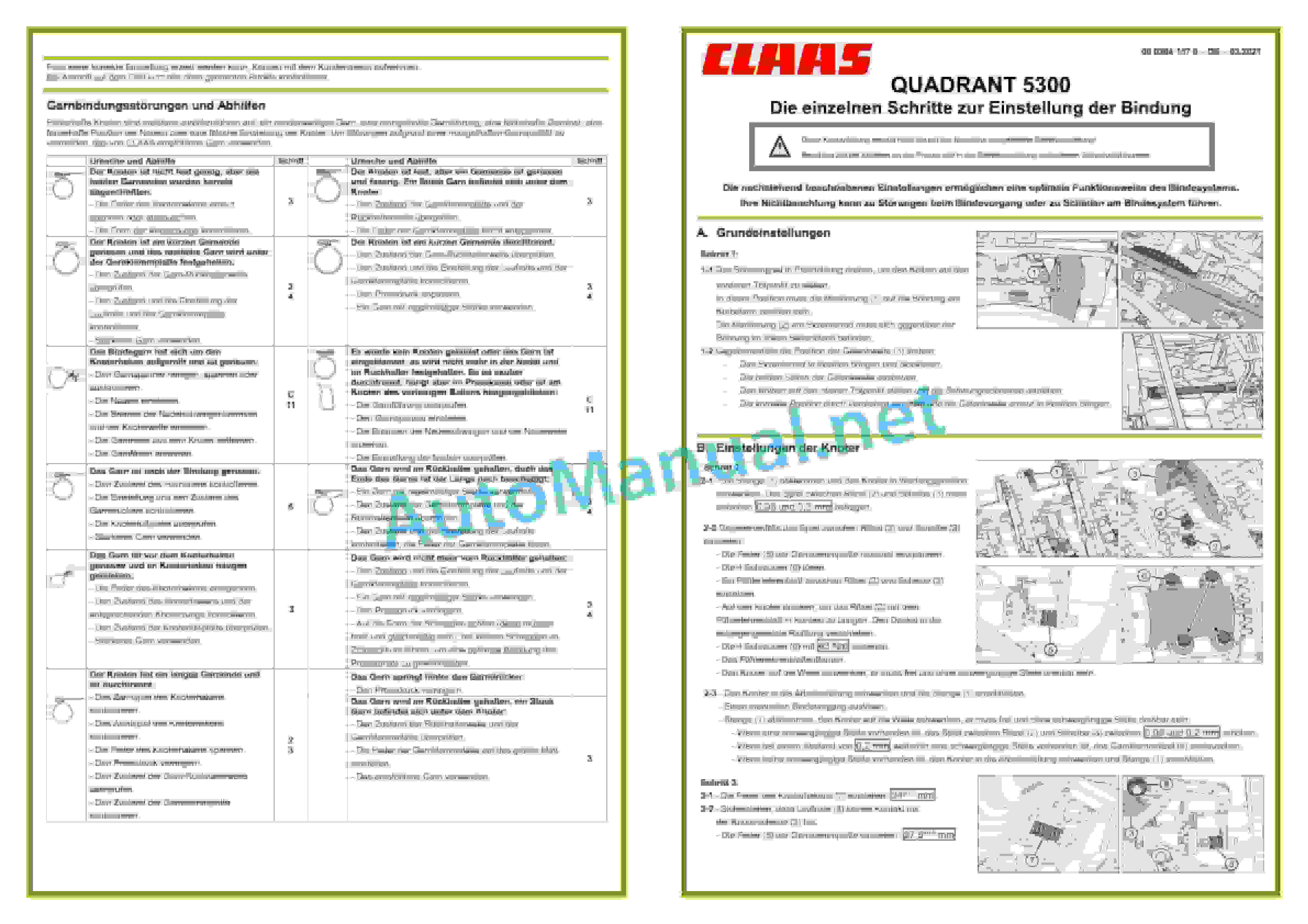
Claas QUADRANT 5300 (J32) Baler Operator Manual DE
$50.00
- Model: QUADRANT 5300 (J32) Baler
- Type Of Manual: Operator Manual
- Language: DE
- Format: PDF(s)
- Size: 154 MB
File List:
– 00 0288 266 2.pdf
– 00 0300 206 6.pdf
– 00 0304 037 2.pdf
– 00 0304 037 3.pdf
– 00 0304 157 0.pdf
00 0300 206 6.pdf
Table of Content:
1 QUADRANT 5300 ROTO FEEDQUADRANT 5300 ROTO CUTQUADRANT 5300 FINE CUT
2 Table of Contents
3 1 Introduction
3.1 1.1 General information
3.2 1.2 Intended use
4 2 Security
4.1 2.1 Recognize warnings
4.2 2.2 Safety instructions
4.3 2.3 Warning symbol
5 3 Machine description
5.1 3.1 Existing models
5.2 3.2 Overview and functions
5.3 3.3 Safety device
5.4 3.4 Work and service areas
5.5 3.5 Type plate and serial number
5.6 3.6 General functional principle
5.7 3.7 Information on the machine
5.8 3.8 Operating terminal
5.9 3.9 PTO shaft and drive
5.10 3.10 Axis
5.11 3.11 Service brake
5.12 3.12 Hitch bracket
5.13 3.13 Hydraulics
5.14 3.14 Receipt
5.15 3.15 Feeding unit
5.16 3.16 Press device
5.17 3.17 Binding system
5.18 3.18 Bale placement
5.19 3.19 Central lubrication system
5.20 3.20 Equipment
6 4 Control and display elements
6.1 4.1 CEMIS 700
6.2 4.2 COMMUNICATOR II
6.3 4.3 OPERATOR
6.4 4.4 ISOBUS Terminal
6.5 4.5 EASY on board
7 5 Technical data
7.1 5.1 Press
7.2 5.2 Safety devices
7.3 5.3 Operating materials
7.4 5.4 Tractor
8 6 Prepare machine
8.1 6.1 Switch off and secure the machine
8.2 6.2 Adjust tractor
8.3 6.3 Adjust machine
8.4 6.4 Attach machine
8.5 6.5 Preparing for work
8.6 6.6 Binding
8.7 6.7 Cutting device
8.8 6.8 Bale weighing device
8.9 6.9 Loading the machine
9 7 Operation
9.1 7.1 General information
9.2 7.2 Movement of the press
9.3 7.3 Before each use
9.4 7.4 Field operation
9.5 7.5 Cutting device
9.6 7.6 Bale parameters
9.7 7.7 CEMIS 700
9.8 7.8 Unclogging the press
9.9 7.9 After Use
9.10 7.10 Detach machine
10 8 Malfunction and remedy
10.1 8.1 Binding
10.2 8.2 Central lubrication system
10.3 8.3 Operating terminal
10.4 8.4 Electrics and electronics
11 9 Maintenance
11.1 9.1 General maintenance instructions
11.2 9.2 Maintenance tables
11.3 9.3 Basic operation
11.4 9.4 Basic settings
11.5 9.5 Maintenance work gearbox
11.6 9.6 Maintenance work clutch
11.7 9.7 Maintenance work axle and wheels
11.8 9.8 Maintenance work brake
11.9 9.9 Maintenance work trailer hitch
11.10 9.10 Maintenance work hydraulic system
11.11 9.11 Electrical/electronics maintenance work
11.12 9.12 Maintenance work Pickup
11.13 9.13 Maintenance work Binding
11.14 9.14 Maintenance work central lubrication
11.15 9.15 Lubrication plan
11.16 9.16 Winterization
12 10 Decommissioning and disposal
12.1 10.1 General information
13 11 EC declaration of conformity
13.1 11.1 General information
00 0304 037 2.pdf
Table of Content:
1 QUADRANT 5300 ROTO FEEDQUADRANT 5300 ROTO CUTQUADRANT 5300 FINE CUT
2 Table of Contents
3 1 Introduction
3.1 1.1 General information
3.2 1.2 Intended use
4 2 Security
4.1 2.1 Recognize warnings
4.2 2.2 Safety instructions
4.3 2.3 Warning symbol
5 3 Machine description
5.1 3.1 Existing models
5.2 3.2 Overview and functions
5.3 3.3 Safety device
5.4 3.4 Work and service areas
5.5 3.5 Type plate and serial number
5.6 3.6 General functional principle
5.7 3.7 Information on the machine
5.8 3.8 Operating terminal
5.9 3.9 PTO shaft and drive
5.10 3.10 Axis
5.11 3.11 Service brake
5.12 3.12 Hitch bracket
5.13 3.13 Hydraulics
5.14 3.14 Receipt
5.15 3.15 Feeding unit
5.16 3.16 Press device
5.17 3.17 Binding system
5.18 3.18 Bale placement
5.19 3.19 Central lubrication system
5.20 3.20 Equipment
6 4 Control and display elements
6.1 4.1 CEMIS 700
6.2 4.2 ISOBUS Terminal
6.3 4.3 EASY on board
7 5 Technical data
7.1 5.1 Press
7.2 5.2 Safety devices
7.3 5.3 Operating materials
7.4 5.4 Tractor
8 6 Prepare machine
8.1 6.1 Switch off and secure the machine
8.2 6.2 Adjust tractor
8.3 6.3 Adjust machine
8.4 6.4 Attach machine
8.5 6.5 Preparing for work
8.6 6.6 Binding
8.7 6.7 Cutting device
8.8 6.8 Bale weighing device
8.9 6.9 Loading the machine
9 7 Operation
9.1 7.1 General information
9.2 7.2 Movement of the press
9.3 7.3 Before each use
9.4 7.4 Field operation
9.5 7.5 Cutting device
9.6 7.6 Bale parameters
9.7 7.7 CEMIS 700
9.8 7.8 Unclogging the press
9.9 7.9 After Use
9.10 7.10 Detach machine
10 8 Malfunction and remedy
10.1 8.1 Binding
10.2 8.2 Central lubrication system
10.3 8.3 Operating terminal
10.4 8.4 Electrics and electronics
11 9 Maintenance
11.1 9.1 General maintenance instructions
11.2 9.2 Maintenance tables
11.3 9.3 Basic operation
11.4 9.4 Basic settings
11.5 9.5 Maintenance work gearbox
11.6 9.6 Maintenance work clutch
11.7 9.7 Maintenance work axle and wheels
11.8 9.8 Maintenance work brake
11.9 9.9 Maintenance work trailer hitch
11.10 9.10 Maintenance work hydraulic system
11.11 9.11 Electrical/electronics maintenance work
11.12 9.12 Maintenance work Pickup
11.13 9.13 Maintenance work Binding
11.14 9.14 Maintenance work central lubrication
11.15 9.15 Lubrication plan
11.16 9.16 Winterization
12 10 Decommissioning and disposal
12.1 10.1 General information
13 11 EC declaration of conformity
13.1 11.1 General information
00 0304 037 3.pdf
Table of Content:
1 Operating Instructions
2 Table of Contents
3 1 Introduction
3.1 1.1 General information
3.2 1.2 Intended use
4 2 Security
4.1 2.1 Recognize warnings
4.2 2.2 Safety instructions
4.3 2.3 Warning symbol
5 3 Machine description
5.1 3.1 Existing models
5.2 3.2 Overview and functions
5.3 3.3 Safety device
5.4 3.4 Work and service areas
5.5 3.5 Type plate and serial number
5.6 3.6 General functional principle
5.7 3.7 Information on the machine
5.8 3.8 Operating terminal
5.9 3.9 PTO shaft and drive
5.10 3.10 Axis
5.11 3.11 Service brake
5.12 3.12 Hitch bracket
5.13 3.13 Hydraulics
5.14 3.14 Receipt
5.15 3.15 Feeding unit
5.16 3.16 Press device
5.17 3.17 Binding system
5.18 3.18 Bale placement
5.19 3.19 Central lubrication system
5.20 3.20 Equipment
6 4 Control and display elements
6.1 4.1 CEMIS 700
6.2 4.2 ISOBUS Terminal
6.3 4.3 EASY on board
7 5 Technical data
7.1 5.1 Press
7.2 5.2 Safety devices
7.3 5.3 Operating materials
7.4 5.4 Tractor
8 6 Prepare machine
8.1 6.1 Switch off and secure the machine
8.2 6.2 Adjust tractor
8.3 6.3 Adjust machine
8.4 6.4 Attach machine
8.5 6.5 Pick-up
8.6 6.6 Front-mounted shredder
8.7 6.7 Binding
8.8 6.8 Cutting device
8.9 6.9 Bale weighing device
8.10 6.10 Load machine
9 7 Operation
9.1 7.1 General information
9.2 7.2 Movement of the press
9.3 7.3 Before each use
9.4 7.4 Field operation
9.5 7.5 Front-mounted shredder
9.6 7.6 Cutting device
9.7 7.7 Bale parameters
9.8 7.8 CEMIS 700
9.9 7.9 Unclogging the press
9.10 7.10 After Use
9.11 7.11 Detach machine
10 8 Malfunction and remedy
10.1 8.1 Binding
10.2 8.2 Central lubrication system
10.3 8.3 Operating terminal
10.4 8.4 Electrics and electronics
10.5 8.5 Front-mounted shredder
11 9 Maintenance
11.1 9.1 General maintenance instructions
11.2 9.2 Maintenance tables
11.3 9.3 Basic operation
11.4 9.4 Basic settings
11.5 9.5 Maintenance work gearbox
11.6 9.6 Maintenance work clutch
11.7 9.7 Maintenance work axle and wheels
11.8 9.8 Maintenance work brake
11.9 9.9 Maintenance work trailer hitch
11.10 9.10 Maintenance work hydraulic system
11.11 9.11 Electrical/electronics maintenance work
11.12 9.12 Maintenance work front-mounted shredder
11.13 9.13 Maintenance work Pickup
11.14 9.14 Maintenance work Binding
11.15 9.15 Maintenance work central lubrication
11.16 9.16 Lubrication plan
11.17 9.17 Winterization
12 10 Decommissioning and disposal
12.1 10.1 General information
13 11 EC declaration of conformity
13.1 11.1 QUADRANT 5300
John Deere Repair Technical Manual PDF
John Deere Repair Technical Manual PDF
John Deere Repair Technical Manual PDF
John Deere Repair Technical Manual PDF
John Deere Repair Technical Manual PDF
John Deere Repair Technical Manual PDF
John Deere POWERTECH E 4.5 and 6.8 L Diesel Engines TECHNICAL MANUAL 25JAN08
John Deere Repair Technical Manual PDF
John Deere Parts Catalog PDF
John Deere Harvesters 8500 and 8700 Parts Catalog CPCQ24910 Spanish
John Deere Repair Technical Manual PDF
John Deere Parts Catalog PDF
John Deere Tractors 7500 Parts Catalog CPCQ26568 30 Jan 02 Portuguese

