Claas Quantum 5500 S S16 S18 4500 S (614) Loader Wagons Operator Manual EN
$50.00
- Model: Quantum 5500 S S16 S18 4500 S (614) Loader Wagons
- Type Of Manual: Operator Manual
- Language: EN
- Format: PDF(s)
- Size: 133 MB
File List:
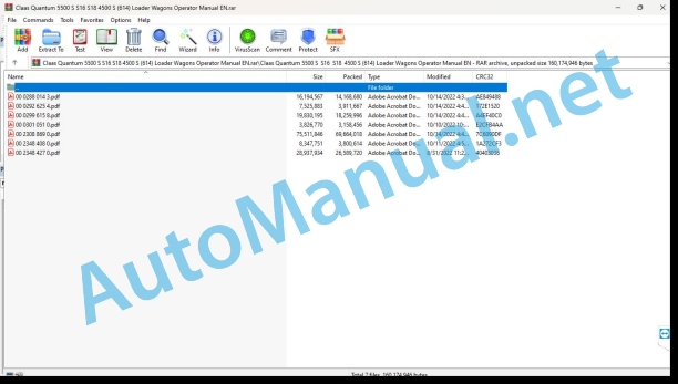
00 0288 014 3.pdf
00 0292 625 4.pdf
00 0299 615 8.pdf
00 0301 051 0.pdf
00 2308 869 0.pdf
00 2348 408 0.pdf
00 2348 427 0.pdf
00 0288 014 3.pdf:
EASY on board app
Table of contents
1 Introduction
1.1 General information
1.1.1 Validity of the manual
1.1.2 Information about this Operator’s Manual
1.1.3 Symbols and notes
1.1.4 Qualified specialist workshop
1.1.5 Maintenance notes
1.1.6 Notes on warranty
1.1.7 Spare parts and technical questions
1.1.8 Technical requirements
1.2 Intended use
1.2.1 Intended use
1.2.2 Reasonably foreseeable misuse
2 Safety
2.1 Identifying warnings
2.1.1 Hazard signs
2.1.2 Signal word
2.2 Safety rules
2.2.1 Meaning of Operator’s Manual
2.2.2 Requirements made on all persons working with the product
2.2.3 Hazard areas
2.2.4 Check interactions with self-propelled machines / tractors and implements
2.2.5 Structural changes
2.2.6 Optional equipment and spare parts
2.2.7 Technical status
2.2.8 Hazard caused by damage to the product
2.2.9 Visibility of work area
2.2.10 Glare and reflections
2.2.11 Unintentional triggering of functions
2.2.12 Hazards caused by signal tones
2.2.13 Unauthorised use
2.2.14 Use of mobile terminal outside the cab
2.2.15 Follow the safety instructions
2.2.16 Respecting technical limit values
2.2.17 Preparing the product for road travel
2.2.18 Hazards when driving on the road and on the field
2.2.19 Hazards when driving on the road with an ISOBUS implement
2.2.20 Switching off the mobile terminal while driving
2.2.21 Hazards from disturbance of WLAN environment
2.2.22 Hazards from covering up the App
2.2.23 Hazards caused by malfunctions of the app
2.2.24 Raised machine parts and loads
3 Product description
3.1 Overview and method of operation
3.1.1 Overview of CWI
3.1.2 Functions of CWI
3.2 Identification plates and identification numbers
3.2.1 CWI identification plate
3.3 Information on the product
3.3.1 Factory settings
3.3.2 Software and hardware version
3.3.3 Seal on the CWI
4 Operating and display elements
4.1 CLAAS Wireless Interface (CWI)
4.1.1 CWI operating elements
4.2 CWI Setup App
4.2.1 Overview of screen
4.2.2 Buttons
4.2.3
4.2.4
4.2.5
5 Technical specifications
5.1 CLAAS Wireless Interface (CWI)
5.1.1 Specification
6 Preparing the product
6.1 Installing the product
6.1.1 Installing the CWI Setup app
6.1.2 Installing the EASY on board app
6.1.3 Connecting the tablet
7 Operation
7.1 Initial operation
7.1.1 Establishing the WLAN connection for the first time
7.1.2 Changing factory settings
7.1.3 Establishing the WLAN connection
7.2 CWI Setup App
7.2.1 Calling up menus
7.2.2 Establishing a secure data connection
7.2.3 Deleting a secure data connection
7.2.4 Displaying the software version
7.3 CWI Setup – Settings
7.3.1 Changing settings
7.3.2 Switching LEDs on and off
7.4 CWI setup – Advanced settings
7.4.1 Deleting the connection partner in CWI
7.4.2 Deleting the connection partner on the tablet
7.4.3 Resetting the CWI to factory settings
7.4.4 Resetting the tablet to factory settings
7.4.5 Switching the CAN filter on and off
7.5 EASY on board App
7.5.1 Launching Operator’s Manual
8 Faults and remedies
8.1 Overview of problems
8.1.1 CWI faults
8.1.2 Fault message: USB charging connection was disconnected
8.1.3 Fault message: Tablet outside WLAN reception area
8.1.4 Fault message: Screen locked
9 Maintenance
9.1 Maintenance schedules
9.1.1 Daily
9.2 Tablet
9.2.1 Cleaning the tablet
9.2.2 Downloading software updates
9.2.3 Updating the operating system
10 Putting out of operation and disposal
10.1 General information
10.1.1 Decommissioning and disposal
11 EC declaration of conformity
11.1 CLAAS Wireless Interface (CWI)
11.1.1 EU Declaration of conformity
12 Technical terms and abbreviations
12.1 Terms and explanations
12.1.1 Abbreviations
12.1.2 Technical terms
00 0292 625 4.pdf:
COMMUNICATOR II
Table of contents
1 Introduction
1.1 Notes on the manual
1.1.1 Validity of manual
1.1.2 Information about this Operator’s Manual
1.1.3 Symbols and notes
1.1.4 Optional equipment
1.1.5 Qualified specialist workshop
1.1.6 Maintenance notes
1.1.7 Notes on warranty
1.1.8 Spare parts and technical questions
1.2 Intended use
1.2.1 Intended use
1.2.2 Reasonably foreseeable misuse
2 Safety
2.1 Identifying warnings
2.1.1 Hazard signs
2.1.2 Signal word
2.2 Safety rules
2.2.1 Meaning of Operator’s Manual
2.2.2 Requirements made on all persons working with the product
2.2.3 Hazard areas
Hazard areas
2.2.4 Interaction between the control terminal and the machine or tractor
2.2.5 Structural changes
2.2.6 Optional equipment and spare parts
2.2.7 Technical status
2.2.8 Danger from damage to the machine
2.2.9 Complying with technical limit values
2.2.10 Preparing the product for road travel
2.2.11 Hazards when driving on the road and in the field
2.2.12 Hazards when driving on the road with an ISOBUS implement
2.2.13 Switching off the terminal while driving
2.2.14 Electrocution by electrical system
2.2.15 Only carry out work on the machine when it is stopped
2.2.16 Maintenance operations and repair work
2.2.17 Raised machine parts and loads
2.2.18 Welding work prohibited
3 Product description
3.1 Overview and method of operation
3.1.1 Overview of COMMUNICATOR II
3.1.2 Function of COMMUNICATOR II
3.2 Identification plates and identification numbers
3.2.1 Identification plate of COMMUNICATOR II
4 Operating and display elements
4.1 COMMUNICATOR II
4.1.1 Terminal
4.1.2 Terminal program
4.2 Universal terminal menu structure (service)
4.2.1 Main menu of universal terminal
4.2.2
4.2.3
4.2.4
4.2.5
4.3 Job processing (task) menu structure
4.3.1 Job processing main menu
4.3.2
4.3.3
4.3.4
4.3.5
4.3.6
5 Technical specifications
5.1 COMMUNICATOR II
5.1.1 Specification
6 Preparing the product
6.1 Switching off and securing the machine
6.1.1 Shut down and secure the machine
7 Operation
7.1 Switching COMMUNICATOR II on/off
7.1.1 Switching COMMUNICATOR II on
7.1.2 Selecting the application
7.1.3 Switching off COMMUNICATOR II
7.2 Programmable keys
7.2.1 Displaying the key assignment
7.2.2 Creating a key assignment
Step 1: Selecting the control and the key
00 0299 615 8.pdf:
1 Machine overview
2 Introduction
Introduction
Validity
3 Contents
4 Preface
Of special importance
Identification plate
Road transport
Operating permit
Operating on public roads
Number plate
Regular inspection as required by law
5 Safety Rules
Designated use
Identification of warning and danger signs
General Safety and Accident Prevention Instructions
PTO Operation
Hydraulic system
Wheels and tyres, threaded fastenings
Maintenance
Sound pressure level
Safety decals with pictorials
6 Specifications
QUANTUM 6800 S
QUANTUM 5500 S-18
QUANTUM 5500 S-16
QUANTUM 5500 S
QUANTUM 4500 S
7 Assembly
Assembly
QUANTUM 6800 S / 5500 S-18 up to 614 0 02242
QUANTUM 5500 S-16 / 5500 S up to 614 0 02242
QUANTUM 4500 S up to 614 0 02242
QUANTUM 6800 S / 5500 S-18 from serial no. 614 0 02243
QUANTUM 5500 S-16 / 5500 S / 4500 S from 614 0 02243
Coupling machine for the first time
8 Prior to operation
Check and observe the following points prior to operation
Coupling to the tractor
Hydraulic articulated drawbar
Ring hitches
Height adjustment of the drawbar
Hitching the forced steering system (optional equipment, only available ex-works)
Adjusting forced steering system
Checking and adjusting the hydraulic pressure
Drive shaft
Adjusting the universal drive shaft
Universal drive shaft with CC taper lock seal
Coupling
Uncoupling
Electrical system
Control unit
ABS air brake system
ABS function test
Adjustment of DIP switches
Hydraulic system
Open hydraulic system (standard system)
Closed hydraulic system
Power-beyond connector
Support foot
After attaching the self-loading forage wagon
Parking the self-loading forage wagon
Air brake system
Two-line system
Towing with tractors without air brake system
Hydraulically operated brake system
Parking brake
Setting brake
Releasing brake
Wheel chocks
Inspection hatch
Unhitching
Self-loading forage wagon with air brake system
Self-loading forage wagon with hydraulically operated brake
Self-loading forage wagon with ABS air brake system
Prior to transportation
Hydraulic drawbar damping (optional equipment, only available ex-works)
Activate drawbar damping
Driving on public roads
9 Operation
Brief introduction
Loading operation
Manual loading operation
Floor conveyor speed
Knife frame
Unloading operation
Articulated drawbar
Indicator light (1)
Loading operation
Lowering and lifting the pick-up
Preselecting the working height of the pick-up
Roll-type crop guard (QUANTUM 6800 S / 5500 S-18)
Baffle plate
Adjusting filling mode (filling automatics)
End of loading operation
Switching floor conveyor manually
Setting floor conveyor speed
Opening/closing the knife frame
Unloading operation
Silage operation
Unloading the load space
2-speed motor floor conveyor (Optional equipment, only available ex-works)
Unloading with cross conveyor (Optional equipment, only available ex-works)
Unloading without cross conveyor
Split tailgate (Optional equipment, only available ex-works)
Opening the lower and top tailgate
Opening the lower part of the tailgate
Load space lighting
Operation of self-loading forage wagon
Loading operation (general)
After use
Standard steering axle (Optional equipment, only available ex-works)
Locking/unlocking standard steering axle
Emergency operation
Optional equipment
Tractor electrical system power supply
Operating unit extension cable
Load-Sensing Hydraulics control line
Drawbar extension for automatic pick-up hitch (M01/0010)
Fill indicator for half load
3. Shredder drum (E03/0050)
Hydraulic connection for tractor (R03/0070)
Slip yoke kit
10 Maintenance
Important Maintenance Instructions
Wheels/tyres
Brakes and axles
Air brake system
Hydraulic system
Lubrication
Diagnostic System
Operation
Assignment of inputs
Assignment of outputs
Brakes and axles
Air brake system
ABS air brake system
Draining compressed air reservoir
Air pipe filter
Cleaning the filter element
Components of the air cleaner
Adjusting the brake – checking the brake cylinder piston stroke
Brake regulator
Brake linings
Forced steering system
Refilling and bleeding the forced steering system
Bleeding steering cylinder
Bleeding master cylinder
Adjusting stroke of master cylinder
Extending master cylinder
Retracting master cylinder
Setting operating pressure for forced steering system
Cutting mechanism
Changing the cutting knives
Knife removal
Knife installation
Adjusting the scraper unit
Drive systems
Main gearbox
Floor conveyor gearbox
Floor conveyor drive with 2-speed motor
Rotor drive
Shredder drum drive (front right)
Shredder drum drive (rear right)
Tensioning the drive chains
Tensioning pick-up drive chain
Shredder drum drive chains
Floor conveyor chains
Adjusting the cut-out clutch for the shredder drum drive
Adjusting the pick-up cut-out clutch
Cleaning the pick-up cut-out clutch
Cam-type cut-out clutch
Air bounce
Lifting and lowering device for air-cushioned axles
Electrical system
Adjusting the reed switches
Setting upper fill indicator
Setting the rotation sensor
Replacing the PSD (programmable module)
Replacing the fuse
Tailgate
Adjusting the tailgate
Adjusting the hydraulic cylinder
Adjusting the support
Hydraulic system
Changing pressure filter
Adjusting the speed of the cross conveyor/floor conveyor
Speed – cross conveyor
Accumulator
Hydraulic hose connections
Gas shock absorber
Drive shaft
Maintenance and lubrication holes
Fasteners
Screw connections
End of season storage
Lubrication chart
11 Lubrication Chart
Safety Instructions
Lubricants
Lubrication
00 0301 051 0.pdf:
PROFI CAM 3
Table of contents
1 Introduction
1.1 Notes on the manual
1.1.1 Validity of manual
1.1.2 Information about this Operator’s Manual
1.1.3 Symbols and notes
1.1.4 Optional equipment
1.1.5 Qualified specialist workshop
1.1.6 Maintenance information
1.1.7 Warranty notes
1.1.8 Spare parts and technical questions
1.2 Intended use
1.2.1 Intended use
1.2.2 Reasonably foreseeable misuse
2 Safety
2.1 Identifying warnings
2.1.1 Hazard signs
2.1.2 Signal word
2.2 Safety rules
2.2.1 Meaning of Operator’s Manual
2.2.2 Observing safety decals and warnings
2.2.3 Optional equipment and spare parts
3 Product description
3.1 Overview and method of operation
3.1.1 How the PROFI CAM works
3.2 Identification plates and identification number
3.2.1 Position of identification plates
3.2.2 Explanation of PROFI CAM identification plate
3.3 Information on the product
3.3.1 CE marking
4 Operating and control elements
4.1 Camera system
4.1.1 Camera system monitor
4.2 Menu structure
4.2.1 Main menu
4.2.2
4.2.3
4.2.4
4.2.5
4.2.6
5 Technical specifications
5.1 PROFI CAM
5.1.1 Monitor
5.1.2 Camera
5.1.3 Switch box
5.1.4 Degree of protection against foreign bodies and water
6 Preparing the product
6.1 Shutting down and securing the machine
6.1.1 Switching off and securing the machine
6.2 Prior to operation
6.2.1 Carry out prior to operation
6.2.2 Installing the sun protection
6.2.3 Aligning the camera
6.2.4 Connecting the camera electrics
7 Operation
7.1 Monitor
7.1.1 Switching on the monitor
7.1.2 Calling up the menu
7.1.3 Setting a menu item
7.1.4 Setting the image orientation
7.1.5 Setting automatic screen darkening
7.1.6 Image mirroring
7.1.7 Setting the trigger view
7.1.8 Setting the follow-up time for trigger view
7.1.9 Setting the display mode
7.1.10 Activating/deactivating a display mode
8 Faults and remedies
8.1 Electrical and electronic system
8.1.1 Overview of problems on PROFI CAM camera system
8.1.2 Replacing the switch box fuse
9 Maintenance
9.1 Maintenance intervals
9.1.1 Every 10 operating hours or daily
9.2 Camera system
9.2.1 Checking the camera system for dirt
9.2.2 Cleaning the camera
9.2.3 Cleaning the switch box
9.2.4 Cleaning the monitor
10 Placing out of operation and disposal
10.1 General Information
10.1.1 Putting out of operation and disposal
11 Technical terms and abbreviations
11.1 Abbreviations
11.1.1 Units
11.1.2 Abbreviations
11.1.3 Technical terms
00 2308 869 0.pdf:
QUANTUM 6800 SQUANTUM 5800 SQUANTUM 5700 SQUANTUM 4700 S
Table of contents
1 To this Operator’s Manual
1.1 Notes on the manual
1.1.1 Validity of the manual
1.1.2 Notes on this Operator’s Manual
1.1.3 Symbols and notes
1.1.4 Optional equipment
1.1.5 Qualified specialist workshop
1.1.6 Notes on maintenance
1.1.7 Notes on warranty
1.1.8 Technical specifications
1.1.9 Spare parts and technical questions
2 Safety
2.1 Intended use
2.1.1 Intended use
2.1.2 Reasonably foreseeable misuse
2.2 Safety rules
2.2.1 Operator’s Manual and other sources of information
Meaning of Operator’s Manual
2.2.2 Personnel qualification and organization
Requirements made on all persons working with the machine
2.2.3 Hazard for children
Children in danger
2.2.4 Coupling machines
Coupling the tractor to the machine
2.2.5 Modifications on the machine
Structural modifications
2.2.6 Additional equipment and spare parts
Additional equipment and spare parts
2.2.7 Workplaces and passengers
Controlling the machine when it is running
Carrying an instructor as a passenger while the machine is in use
2.2.8 Technically perfect condition
Operation only after a proper handover inspection
Operation only after the machine has been properly put into operation
Technically perfect condition of the machine
Danger resulting from damage to the machine
Complying with technical limit values
2.2.9 Hazard zones
Hazard zones
Presence between machine and tractor
Projected objects
Danger with drive engaged
Risk of injury at the PTO shaft
Risk of injury at the universal drive shaft
Danger from continued running of machine parts
2.2.10 Safety devices
Keeping the safety devices functional
2.2.11 Personal protective equipment
Personal protective equipment
Wearing suitable clothing
2.2.12 Safety markings
Keeping safety decals legible
2.2.13 Road safety
Dangers when driving on road and field
Danger of tipping
Preparing the machine for road transport
Parking the machine safely
Tractor and machine combination parked unattended
Keep the machine free of foreign objects
2.2.14 Operating utilities
Unsuitable operating utilities
Safe handling of operating and auxiliary utilities
Environmental protection and disposal
2.2.15 Dangers from the place of use
Risk of fire
2.2.16 Hazard sources at the machine
Electric shock from electrical system
Vibrations could lead to ill health
Pressurised fluids
Compressed air
Hot surfaces
2.2.17 Hazard when climbing on and leaving the machine
Safe climbing on and leaving the machine
2.3 Safety decals on the machine
2.3.1 Notes on safety decals
2.3.2 Position of safety decals
3 Machine description
3.1 Overview and method of operation
3.1.1 Machine overview
3.1.2 Function of machine
Function of self-loading and silage wagon
3.2 Optional equipment
3.2.1 COMMUNICATOR II*
3.2.2 ISOBUS connecting cable*
3.2.3 Slip yoke*
3.2.4 Fill level sensor*
3.2.5 Loading space lighting*
3.2.6 Battery cable*
3.2.7 Order printer* for ISOBUS
3.2.8 Torque-controlled unloading*
3.2.9 Load sensing hydraulics control line*
3.2.10 Drawbar extension for hitch attachment*
3.2.11 Half-load height sensor*
3.2.12 Third proportioning roller*
3.2.13 Hydraulic connection for tractor, 3-way
3.3 Identification plates and identification number
3.3.1 Spare parts and technical questions
3.3.2 Machine identification plate
3.3.3 Identification plate of the drawbar
3.3.4 Identification plate of the hitch eye
3.4 Information on the machine
3.4.1 Stickers on the machine
4 Operating and display elements
4.1 Exterior operator panel
4.1.1 Cutting trough
4.2 Controls
4.2.1 Parking brake
4.2.2 Compressed air brake
4.2.3 Knives
4.2.4 Rotary valve for the pneumatic suspension*
4.2.5 Floor conveyor / cross conveyor speed*
4.3 ISOBUS terminal
4.3.1 Screen
4.3.2 Menu bar
4.3.3 Data field
4.3.4 Status bar
4.3.5 Softkey
4.3.6 Softkeys – overview
4.3.7 Program version
5 Technical specifications
5.1 QUANTUM 6800 S
5.1.1 Dimensions
5.1.2 Weights
5.1.3 Pick-up
5.1.4 Cutterbar
5.1.5 Tyre pressure
5.1.6 Requirements of the tractor
5.1.7 Electric system
5.1.8 PTO shaft speed
5.1.9 Sound pressure level
5.1.10 Lubricants
5.2 QUANTUM 5800 S
5.2.1 Dimensions
5.2.2 Weights
5.2.3 Pick-up
5.2.4 Cutterbar
5.2.5 Tyre pressure
5.2.6 Requirements of the tractor
5.2.7 Electric system
5.2.8 PTO shaft speed
5.2.9 Sound pressure level
5.2.10 Lubricants
5.3 QUANTUM 5700 S
5.3.1 Dimensions
5.3.2 Weights
5.3.3 Pick-up
5.3.4 Cutterbar
5.3.5 Tyre pressure
5.3.6 Requirements of the tractor
5.3.7 Electric system
5.3.8 PTO shaft speed
5.3.9 Sound pressure level
5.3.10 Lubricants
5.4 QUANTUM 4700 S
5.4.1 Dimensions
5.4.2 Weights
5.4.3 Pick-up
5.4.4 Cutterbar
5.4.5 Tyre pressure
5.4.6 Requirements of the tractor
5.4.7 Electric system
5.4.8 PTO shaft speed
5.4.9 Sound pressure level
5.4.10 Lubricants
6 Machine preparation
6.1 Switching off and securing the machine
6.1.1 Switching off and securing machine
6.2 Assembling the machine
6.2.1 Overview of shipping package
6.2.2 Attach side wall extensions
6.2.3 Attach side wall extensions
6.2.4 Fitting the universal drive shaft to the machine
6.2.5 Connecting the ISOBUS cable*
6.2.6 Fitting optional equipment
6.3 Access to workplace and maintenance positions
6.3.1 Entering and leaving the loading bay
6.4 Adapting the tractor
6.4.1 Coupling device
6.4.2 Attaching hitching for forced steering system*
6.4.3 Configuring the tractor air brake system
6.4.4 Installing the COMMUNICATOR II*
6.4.5 Installing the OPERATOR*
6.5 Adapting the machine
6.5.1 Adapting the hydraulics
Open hydraulic system (standard system)
Closed hydraulic system (constant-pressure or load-sensing)
Connecting the load sensing control line
6.5.2 Adjusting the hydraulic articulated drawbar
Hydraulic articulated drawbar with ball head bottom hitching
Hydraulic articulated drawbar – attachment using hitch eye
Anti-rotation lock
Adjusting the piston rod
6.6 Coupling the machine to the tractor
6.6.1 General instructions
6.6.2 Connecting the cable for the driving lights
6.6.3 Connecting COMMUNICATOR II*
On tractors without ISOBUS socket
On tractors with ISOBUS socket
6.6.4 Connecting the OPERATOR*
6.6.5 Connecting the hydraulic hose lines
Open hydraulic system or closed hydraulic system without load-sensing control line:
Closed hydraulic system (load sensing) with load-sensing control line:
Power-beyond socket:
6.6.6 Hitching up the drawbar using a hitch eye
6.6.7 Hitching the drawbar with ball joint bottom hitching
6.6.8 Hitching up the forced steering system*
Basic setup
Hitching up the tow bar
Adjusting the forced steering system protector shield
Adjusting straight-ahead travel
Checking the hydraulic pressure
Setting the hydraulic pressure
6.6.9 Checking the length of the universal drive shaft
Universal drive shaft – shortest operating position
Universal drive shaft – longest operating position
6.6.10 Adapting the length of the universal drive shaft
6.6.11 Fitting the universal drive shaft
6.6.12 Adjusting the lower link
6.6.13 Connecting the compressed air brake*
ABS compressed air braking system*
ABS operational check
6.6.14 Connecting hydraulically applied brake*
6.6.15 Connecting the breakaway brake*
6.6.16 Raising the stand
6.6.17 Releasing the parking brake
6.6.18 Removing the wheel chocks
6.7 Unhitching the machine from the tractor
6.7.1 Information to be observed
6.7.2 Positioning the wheel chock at the wheel
6.7.3 Apply the parking brake
6.7.4 Extending the stand
6.7.5 Removing the universal drive shaft
6.7.6 Uncoupling the forced steering system*
Unhooking the tow bar
6.7.7 Unhooking the tow bar with ball head bottom hitching
6.7.8 Disconnecting the cable for drive lights
6.7.9 Disconnecting the COMMUNICATOR II*
On tractors without ISOBUS socket
On tractors with ISOBUS socket
6.7.10 Disconnecting the OPERATOR*
6.7.11 Disconnecting the hydraulic hoses
6.7.12 Disconnecting the compressed-air operated brake
ABS compressed air braking system*
6.7.13 Uncoupling the hydraulically applied brake*
6.7.14 Uncoupling the breakaway brake*
6.8 Loading and lashing down the machine
6.8.1 Loading and lashing down the machine
7 Operation
7.1 Driving with the loader wagon
7.1.1 Checking before travel
7.1.2 Activating hydraulic drawbar damping
7.1.3 Activating air suspension*
7.1.4 Manoeuvring the machine with tractor without compressed-air system
7.1.5 Locking the steered trailing axle
7.2 Driving on the road
7.2.1 General instructions
7.2.2 Driving licence categories required for Germany
7.2.3 Documents to be carried on the machine
7.2.4 Modifications to the machine
7.2.5 Licence and registration requirements
7.2.6 Regular inspection according to § 29 StVZO (German Road Traffic Regulations)
7.2.7 Operating on public roads
7.2.8 Work lights
7.3 Ajusting before loading
7.3.1 Adjusting before loading
7.3.2 Adjusting the working height of the pick-up
7.3.3 Adjusting the roller crop press
7.3.4 Setting the baffle plate
7.4 Loading the wagon
7.4.1 Filling the loading space evenly
7.4.2Loading process
7.5 Adjusting before discharging
7.5.1 Discharging with the cross conveyor*
7.5.2 Discharging without the cross conveyor*
7.5.3 Adjusting the sectioned tailgate*
Open the upper and lower tailgates
Open the lower part of the tailgate
7.6 Unloading the wagon
7.6.1 Opening the tailgate
7.7 ISOBUS control unit
7.7.1 Description
General instructions
7.7.2 Explanations regarding the ISOBUS terms
7.8 ISOBUS menu structure
7.8.1 Notes on the menu structure
7.8.2 Main menu
7.8.3
7.8.4
7.8.5
7.9 Switching the ISOBUS terminal on/off
7.9.1 Before switching the terminal on
7.9.2 Switching on the terminal
7.9.3 Starting the control program
7.9.4 Switching the terminal off
7.10 Calling up ISOBUS menus
7.10.1 Changing the main menu
7.10.2 Changing the sub-menu
7.10.3 Exit the submenu
7.11 ISOBUS transport
7.11.1 Activating the transport position
7.11.2 Activating the transport position
7.11.3 Raising/lowering the articulated drawbar
7.11.4 Activating drawbar damping
7.11.5 Locking and unlocking the steered trailing axle
7.11.6 Switching the worklights* on and off
7.12 Loading – automatic operation ISOBUS
7.12.1 Select
7.12.2 Raising to the headland position
7.12.3 Lowering to the working position
7.12.4 Floor conveyor control system in the
Torque display (M)
Switching the floor conveyor drive on and off automatically
Adjusting the threshold value
7.12.5 Switching on the floor conveyor briefly
7.12.6 Raising and lowering the pick-up
7.12.7 Removing blockages in the feed channel
7.12.8 Filling level display*
7.12.9
7.12.10 Exit
7.13 Loading – manual operation ISOBUS
7.13.1 General instructions
7.13.2 Select
7.13.3 Loading the machine manually
7.13.4 Opening and closing the cutting trough
Opening the cutting trough
Closing the cutting trough
7.13.5 Opening and closing the cutter chamber from the external control panel
Open the cutting trough completely
Closing the cutting frame completely
7.13.6 Increasing and reducing the speed of the floor conveyor
7.13.7 Reversing the floor conveyor drive
7.13.8 Switching the pick-up drive on and off
7.13.9 Exit
7.14 Unloading – automatic operation ISOBUS
7.14.1 Select
John Deere Repair Technical Manual PDF
John Deere Repair Technical Manual PDF
John Deere Repair Technical Manual PDF
John Deere Parts Catalog PDF
John Deere Tractors 7500 Parts Catalog CPCQ26568 30 Jan 02 Portuguese
John Deere Repair Technical Manual PDF
John Deere Repair Technical Manual PDF
John Deere Diesel Engines POWERTECH 2.9 L Component Technical Manual CTM126 Spanish
John Deere Repair Technical Manual PDF
John Deere Repair Technical Manual PDF
John Deere POWERTECH E 4.5 and 6.8 L Diesel Engines TECHNICAL MANUAL 25JAN08
John Deere Repair Technical Manual PDF

