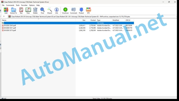
Claas Rollant 250 255 Uniwrap (726) Baler Technical System ES
$300.00
- Model: Rollant 250 255 Uniwrap (726) Baler
- Type Of Manual: Technical System
- Language: ES
- Format: PDF(s)
- Size: 8.3 MB
File List:
00 0293 534 0.pdf
00 0293 535 1.pdf
00 0293 537 0.pdf
00 0293 534 0.pdf:
Electrical installation Rollant 240 – 250
Assembly of connection diagrams
central electrical system
Rollant 240/250 Standard central electrical system
Rollant 250 Comfort central electrical system
UNIWRAP central electrical system
Module pin assignment
Module A23 Rollant 240/250 Standard
Module A23 – 1 Rollant 250 Comfort and Rollant 250 Comfort for Uniwrap
Module A23 – 2 Rollant 250 Comfort and Rollant 250 Comfort for Uniwrap
Module A22 – Uniwrap wrapper (Pin assignment in the X100 socket)
Fixing fuses and relays in the connection diagrams
01a – 40c
01a – Supply of the main tension system Rollant 240/250 Standard
01b – Main tension system supply Rollant 250 Comfort
01c – Supply of the main tension system Rollant 250 Comfort for UNIWRAP
01d – Power supply to the main UNIWRAP voltage system
04a – Circulation blocking valve (with central electrical system) Rollant 250 Comfort
04b – Rollant 250 Comfort circulation blocking valve for UNIWRAP
04c – UNIWRAP circulation blocking valve
05a – Terminal Rollant 250 Comfort
05b – UNIWRAP terminal up to machine number 726 00 130
06a – CAN-Bus, voltage supply for Rollant 240/250 Standard modules
06b – CAN-Bus, voltage supply of Rollant 250 Comfort modules
06c – CAN-Bus, power supply of Rollant 250 Comfort modules for UNIWRAP
06d – CAN-Bus, power supply from the UNIWRAP modules to machine no. 72900130
06e – CAN-Bus, power supply of the UNIWRAP modules from machine no. 72900131
07a – Rotocut Rollant 240/250 Standard
07b – Rotocut Rollant 250 Comfort / Comfort for UNIWRAP
11a – Activation of the Rollant 240/250 Standard tying
11b – Activation of the Rollant 250 Comfort / Comfort tying for UNIWRAP
12a – Open / close tailgate – Rollant 250 Comfort / Comfort for UNIWRAP
19a – Load/unload UNIWRAP bales
20a – Raise / lower the Pickup – Rollant 250 Comfort / Comfort for UNIWRAP
21a – Rotation of the avvolgitore arm – UNIWRAP
22a – Open / close the plastic tape knives, control plastic tape breakage – UNIWRAP
32a – Rear light, position light (with central electrical system)
40a – Additional sockets
40b – Additional sockets
40c – Additional female sockets
cable trunk
Cable trunk A – 1 part (Rollant 250 Standard)
Cable trunk A – 2 part (Rollant 250 Standard)
Cable trunk B – 1 part (Rollant 250 Comfort / Rollant 250 Comfort for UNIWRAP)
Cable trunk B – 2 part (Rollant 250 Comfort / Rollant 250 Comfort for UNIWRAP)
Cable trunk B – 3 part (Rollant 250 Comfort / Rollant 250 Comfort for UNIWRAP)
Cable trunk C (Rollant 250 Comfort / Rollant 250 Comfort for UNIWRAP)
Cable trunk D (Rollant 250 Comfort for UNIWRAP)
Cable trunk K (UNIWRAP)
Cable trunk L (UNIWRAP)
Cable trunk M (UNIWRAP)
Alphabetical index
0293 534.0
00 0293 535 1.pdf:
Technical systems – Electrical installation ROLLANT 254/255 UNIWRAP
Assembly of connection diagrams
central electrical system
ROLLANT 254/255 Standard
ROLLANT 254/255 Comfort – equipped with CCT
ROLLANT 254/255 Comfort – equipped with COMMUNICATOR
Module pin assignment
Module A23 Rollant 254/255 Standard
Module A23 -1 Rollant 254/255 Comfort – equipped with CCT
ROLLANT 254/255 Comfort – equipped with CCT
Module A23 -2 Rollant 254/255 Comfort – equipped with CCT
ROLLANT 254/255 Comfort – equipped with COMMUNICATOR
A20 CCU module – ROLLANT 254/255 Comfort – equipped with COMMUNICATOR
Module A22 – Uniwrap wrapper (Pin assignment in the X100 socket)
Fixing in the connection diagrams of the fu
Connection diagrams 01a – 40a
01a – Supply of the main tension system ROLLANT 254/255 Standard
01b – Supply of the main voltage system ROLLANT 254/255 Comfort – with CCT equipment
01c – Supply of the main tensioning system ROLLANT 255 Comfort for UNIWRAP – with CCT equipment
01d – Power supply to the main voltage system ROLLANT 254/255 Comfort – equipped with Communicator
01e – Supply of the main tensioning system ROLLANT 255 Comfort for UNIWRAP – equipped with Communicator
01f – UNIWRAP main voltage system power supply
04a – ROLLANT 254/255 Comfort circulation blocking valve – with CCT equipment
04b – ROLLANT 254/255 Comfort circulation blocking valve for UNIWRAP – with CCT equipment
04c – ROLLANT 254/255 Comfort circulation blocking valve – equipped with Communicator
04d – ROLLANT 254/255 Comfort circulation blocking valve for UNIWRAP – equipped with Communicator
04e – UNIWRAP circulation blocking valve
05a – ROLLANT 254/255 Standard Terminal
05b – ROLLANT 254/255 Comfort Terminal – equipped with CCT
05c – ROLLANT 254/255 Comfort Terminal for UNIWRAP – equipped with CCT
06a – CAN-Bus, power supply for ROLLANT 254/255 Standard modules
06b – CAN-Bus, power supply of the ROLLANT 254/255 Comfort modules – with CCT equipment
06c – CAN-Bus, power supply of ROLLANT 255 Comfort modules for UNIWRAP – with CCT equipment
06d – CAN-Bus, power supply of the ROLLANT 254/255 Comfort modules – with Communicator equipment
06e – CAN-Bus, power supply of the ROLLANT 255 Comfort modules for UNIWRAP – with Communicator equipment
06f – CAN-Bus, power supply from the UNIWRAP modules to machine no. 130
06g – CAN-Bus, power supply of UNIWRAP modules from machine no. 131
07a – Rotocut ROLLANT 254/255 Standard
07b – Rotocut ROLLANT 254/255 Comfort / Comfort for UNIWRAP – with CCT equipment
07c – Rotocut ROLLANT 254/255 Comfort / Comfort for UNIWRAP – equipped with Communicator and reversing switch (Z48) – compare with diagram 7d
07d – Rotocut ROLLANT 254/255 Comfort / Comfort for UNIWRAP – equipped with Communicator and reversing sensor (B131) – compare with diagram 7c
11a – Activation of the ROLLANT 254/255 Standard tying
11b – Activation of ROLLANT 254/255 Comfort / Comfort tying for UNIWRAP – with CCT equipment
11c – Activation of the ROLLANT 254/255 Comfort / Comfort tying for UNIWRAP – equipped with Communicator and tailgate closed switch (Z16) – compare with diagram 11d
11d – Activation of the ROLLANT 254/255 Comfort / Comfort tying for UNIWRAP – equipped with Communicator and tailgate closed sensor (B135) – compare with diagram 11c
12a – Open / close the rear hatch sera ROLLANT 254/255 Comfort / Comfort for UNIWRAP – with CCT equipment
12b – Open / close the tailgate ROLLANT 254/255 Comfort / Comfort for UNIWRAP – with Communicator equipment
19a – Load/unload UNIWRAP bales
20a – Raise / lower the ROLLANT 254/255 Comfort / Comfort Pickup for UNIWRAP – with CCT equipment
20b – Raise / lower the ROLLANT 254/255 Comfort / Comfort Pickup for UNIWRAP – equipped with Communicator
21a – Rotate the UNIWRAP wrapping arm
22a – Open/close the plastic tape blades Check for breakage of the plastic tape
32a – Rear light, position light (with central electrical system)
40a – Additional ROLLANT 254/255 Comfort / Comfort sockets for UNIWRAP – equipped with Communicator
Cable trunks A – M
Cable trunk A – 1 part (ROLLANT 254/255 Standard)
Cable trunk A – 2 part (ROLLANT 254/255 Standard)
Cable trunk B – 1 part (ROLLANT 254/255 Comfort)
Cable trunk B – 2 part (ROLLANT 254/255 Comfort)
Cable trunk B – 3 part (ROLLANT 254/255 Comfort)
Cable trunk C (ROLLANT 254/255 Comfort)
Cable trunk D – 1 part (ROLLANT 255 Comfort for Uniwrap)
Cable trunk D – 2 part (ROLLANT 255 Comfort for Uniwrap)
Cable trunk D – 3 part (ROLLANT 255 Comfort for Uniwrap)
Cable trunk E (ROLLANT 255 Comfort for Uniwrap)
Cable trunk K (UNIWRAP)
Cable trunk L (UNIWRAP)
Cable trunk M (UNIWRAP)
Alphabetical index
0293 535.1
00 0293 537 0.pdf:
Technical Systems UNIWRAP hydraulic installation
1 Hydraulic connection diagram
1.1 Hydraulic connection diagram up to machine number 72600130
1.2 Hydraulic connection diagram from machine number: 72600131 with tilting platform shut-off valve (631)
1.3 Hydraulic connection diagram from machine number: 72600531, with clamping shear distributor (769)
1.4 Hydraulic connection diagram from machine no.: 72601047, with valve combination (630, 706, 769), without 3-stage restrictor (645)
1.5 Hydraulic connection diagram from machine number: 72601047, with valve combination (630, 706, 769), with 3-level restrictor (645)
2 Prerequisites for use
2.1 Close the circulation blocking valve (Y77)
2.2 Connection to the tractor hydraulic system
3 Valve block
3.1 Valve block, up to machine no. 130
3.2 Valve block, from machine no. 131, with shut-off valve for service work on the tilting platform (631)
4 Individual components
4.1 Initial pressure regulator (763)
4.2 Circulation blocking valve (Y77-2)
4.3 Taping arm control unit (Y133)
4.4 Tilting platform control unit (Y135/Y136)
4.4.1 Up to machine no.: with block valve block
4.4.2 From machine no.: without block valve block
4.5 Taping table control unit (Y137 / Y138)
4.6 Control unit for clamping shears (Y139 / Y140)
4.7 Flow regulator (630)
4.8 Pressure limiting valve (706)
4.9 Taping arm motor (234)
4.10 Taping table motor (235)
4.11 Tilting platform shut-off valve (631)
4.12 Hydraulic cylinder clamping shears (374)
4.13 Flow divider for clamping shears (769)
4.14 Taping arm motor valve block (4)
4.15 3 level restrictor
4.16 Valve combination (7)
4.17 Distributor (8)
0293 537.0
John Deere Repair Technical Manual PDF
John Deere Repair Technical Manual PDF
John Deere Repair Technical Manual PDF
John Deere Repair Technical Manual PDF
John Deere Repair Technical Manual PDF
John Deere Diesel Engines POWERTECH 2.9 L Component Technical Manual CTM126 Spanish
John Deere Repair Technical Manual PDF
John Deere Repair Technical Manual PDF
John Deere Application List Component Technical Manual CTM106819 24AUG20
John Deere Repair Technical Manual PDF
John Deere Diesel Engines PowerTech 4.5L and 6.8L – Motor Base Technical Manual 07MAY08 Portuguese
John Deere Repair Technical Manual PDF
John Deere Parts Catalog PDF
John Deere Tractors 6300, 6500, and 6600 Parts Catalog CQ26564 (29SET05) Portuguese


