Claas Rollant 374 354 Rc Pu 1,85 (763) Balers Assembly Instruction EN
$50.00
- Model: Rollant 374 354 Rc Pu 1,85 (763) Balers
- Type Of Manual: Assembly Instruction
- Language: EN
- Format: PDF(s)
- Size: 67.6 MB
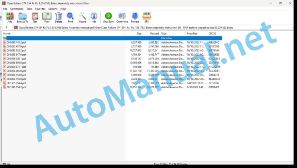
File List:
00 0290 143 2.pdf
00 0292 437 0.pdf
00 0293 345 2.pdf
00 0295 947 0.pdf
00 0296 038 1.pdf
00 0296 859 0.pdf
00 0300 374 1.pdf
00 0304 065 0.pdf
00 0304 154 0.pdf
00 0304 155 0.pdf
00 1325 214 4.pdf
00 1393 754 2.pdf
00 0293 345 2.pdf:
Installation guidance
Automatic central lubrication of bearings
Introduction
Important
Kennzeichnung von Warn- und Gefahrenhinweisesen
Allgemeine Sicherheits- und Unfallverhtungsvorschriften
Abstellen der Maschine
Bestimmunggeme Verwendung
Scope of delivery (0851 328.2)
Scope of delivery (0860 797.1)
Maschine vorbereiten
Press sichern
Schutzvorrichtungen der Heckklappe rechts und leftsausbauen
Only for kit 851 328.2
Bis machine number:
Trger des Verteilerblocks attachment
Lcher fr den Schlag der Fettpumpe
Hole for the lubrication line of the tailgate, left side
Only for kit 851 328.2
Bis machine number:
Sttze fr die Bis machine number:
Maschinen ohne MPS – Hole for the fixing of the Smierleitung der Heckklappe, left side
Verteilerblock der Fettpumpe montieren
Hauptschmier module
Sttze der Fettpumpe
Grease pump
Anschlag der Fettpumpe
Anschlag der Fettpumpe einstellen
Leitungen montieren
Grease block and grease pump
Hauptschmiermodul – Grease pump
Lubrication of the right side of the tailgate – with MPS equipped machine
Right side
Left Side
Schmierung der rechten Seite der Heckklappe – Maschinen ohne MPS
Right side
Left Side
Schmierung der linken Seite der Heckklappe – mit MPS ausgestattete Maschinen
Die linke Seite der Heckklappe schmieren – Maschinen ohne MPS
Hauptschmiermodul – Schmierblock des vorderen Teils der Maschine
Leitungen attached
Schutzvorrichtungen der Heckklappe rechts und lefts montieren
Use and maintenance
Operating
Increase in Durchsatzes
Verringerung des Durchsatzes
Maintenance
Assmbly uctions
Central roller lubrication system
Introduction
Important
Marking of warning and danger notes
General safety regulations and instructions for the avoidance of accidents
Leaving the machine
Intended use
Scope of parts (0851 328.2)
Scope of parts (0860 797.1)
Preparation of the machine
Securing bales
Removing right and left tailgate guards
kit 851 328.2 only
Until machine N_x001E_ :
Fitting support for spreader unit
Holes for lubrication pump stop
Hole for lubrication line in tailgate, left hand side.
kit 851 328.2 only
Until machine N_x001E_ :
Drilling holes in support for lubrication pump
kit 851 328.2 only
Until machine N_x001E_ :
Machines without MPS – hole for fixing lubrication line in tailgate, left-hand side
Fitting spreader unit and lubrication pump
Main lubrication block
Support for lubrication pump
Lubrication pump
Lubrication pump stop
Adjusting lubrication pump stop
Fitting lines
Lubrication blocks and lubrication pump
Main lubrication block – lubrication pump
Lubrication of right hand side of tailgate – machines with MPS
Right side
Left side
Lubrication of right hand side of tailgate – machines without MPS
Right side
Left side
Lubrication of left hand side of tailgate – machines with MPS
Lubrication of left hand side of tailgate – machines without MPS
Main lubrication block – lubrication block on front part of machine
Attaching lines
Fitting right and left tailgate guards
Operation and maintenance
Operation
Increasing output
Reducing output
Maintenance
Installation notice
Centrale de graissage automatique des roulements
Introduction
Important
Characterization of the indications sur les dangers
Consignes gnrales de scurit et de prvention des accidents
Stationnement de la machine
Utilization conforme la destination
Lot de pices (0851 328.2)
Lot de pices (0860 797.1)
Preparation of embly of the right and left rear door protections
kit 851 328.2 only
Jusque machine N_x001E_ :
Mise en place du support du bloc rpartiteur
Trous pour la bute de la pompe de graissage
Trou pour la conduite de graissage de porte arrire, ct gauche
kit 851 328.2 only
Jusque machine N_x001E_ :
Perage du support pour pompe graisse
kit 851 328.2 only
Jusque machine N_x001E_ :
Machines sans MPS – hole for fixer la conduite de graissage de porte arrire, cte gauche
Montage du bloc rpartiteur et de la pumpe graisse
Bloc de graissage principal
Grease pump support
Pompe graisse
Bute de pompe graisse
Adjustment of the bute of the grease pump
Montage des conduites
Blocs de graissage et pompe graisse
Bloc de graissage principal – Pompe graisse
Graissage du cte droit de la porte arrire – machines quipe du MPS
Right side
Graissage de arrire – machines quipe du MPS
Graissage du cte gauche de la porte arrire – machines sans MPS
Bloc de graissage principal – Bloc de graissage partie avant de la machine
Fixation of conduits
Montage des protections de porte arrire droite et gauche
Use and maintenance
Utilization
Augmentation du dbit
Diminution du dbit
Maintenance
Assembly instructions
Central lubrication system for automatic bearing lubrication
Introduction
Important!
Labeling of hazard notices
General instructions for safety and accident prevention
Parking the machine
Intended use
Parts list (0851 328.2)
Parts list (0860 797.1)
Preparing the machine
Securing the press
Removing the protection for the right and left rear door
only seen 851 328.2
To machine no.:
Installation of attachment for distribution unit
Hole for grease pump stop
Hole for feed line for rear door, only seen 851 328.2
To machine no.:
Drgrease pump
only seen 851 328.2
To machine no.:
Machines without MPS – hole for fastening for feed line to rear door, left side
Installation of distribution unit and grease pump
Main lubrication unit
Attached to the grease pump
Grease pump
The grease pump stops
Adjustment of the grease pump stop
Installation of wiring
Lubricating units and grease pump
Main lubrication unit – grease pump
Lubrication of the right side of the rear door – machines with MPS
Right side
Left side
Lubrication of the right side of the rear door – machines without MPS
Right side
Left side
Lubrication of the left side of the rear door – machines with MPS
Lubrication of the left side of the rear door – machines without MPS
Main lubrication unit – Lubrication unit at the front of the machine
Connection of wires
Installation of protective plates for the right and left rear door
Operation and maintenance
Operation
Increase the amount
Reduce the amount
Maintenance
Assembly instructions
Automatic lubrication system for roller bearings
Important
Warning symbols
General instructions for safety and accident prevention
Parking the machine
Use in accordance with the purpose
Introduction
Parts (0851 328.2)
Parts (0860 797.1)
Preparation of the machine
Securing the press
Dismantling the guards on the left and right rear door
only batch 851 328.2
To machine number:
Installation of the spreader support
Hole for the end stop of the lubrication pump
Hole for the lubrication line to the rear door on the left side
only batch 851 328.2
To machine number:
Drilling the support for the lubrication pump
only batch 851 328.2
To machine number:
Machines without MPS – hole to attach the lubrication line to the rear door on the left side
Assembly of the spreading unit and the lubrication pump
First lubrication unit
Lubrication pump support
Lubrication pump
Lubrication pump end stop
Setting the end stop of the lubrication pump
Installation of the wires
Lubrication units and lubrication pump
First lubrication unit – Lubrication pump
Lubrication of the right part of the rear door – machines with MPS
Right side
Left side
Lubrication of the right part of the rear door – machines without MPS
Right side
Left side
Lubrication of the left part of the rear door – machines with MPS
Lubrication of the left part of the rear door – machines without MPS
First lubrication unit – Lubrication unit on the front of the machine
Fastening the wires
Mounting the guards on the left and right rear door
Operation and care and maintenance
Operation and maintenance
To increase the flow
To reduce the flow
Maintenance
Installation instructions
Automatic laakeridein voitelulaite
Alcosanat
Vaaratilanteit sht brand n Turvalliasjaja ja kalneumoksien vtmista ylesoOsanatelho (0851 328.2)
Osanakelto (0860 797.1)
Esimilist decision
Puristime attachment
Oikman- ja vasemmanpuoleisen takaluukun suojuksen irrotus
only series 851 328.2
Koneen numeroon sakke:
Jakosinuntu tuen asentamine sylheen
Reit voitelupumpun stinta vrt
Reik takaluukun voiteluletkulle, vasen puoli
only series 851 328.2
Koneen numeroon sakke:
Reikien poraaminen voitelumppua vrn
only series 851 328.2
Koneen numeroon sakke:
Koneet, joissa ei ole MPS: – Reik takaluukun voiteluletkun tgt vrten, vasen puoli
Jakosinut ja voitelupumpun asentaminen
Pvoiteluiksuksi
Voitelupumpun tuki
Voile pump
Voitelupumpun the limit time
Voitelupumpun syttimen ttt
Letkujen installation
Voitelu unitet yes voitelu pump
Pvoiteluiksuksi – voitelupumpu
Takaluukun oikeen puolen voitelu – MPS:l varustustut koeneet
mman puolen voitelu – MPS:l varusetut koenet
Takaluukun vasemman puolen voitelu – koeneet ilman MPS:
Pvoiteluiksuksi – koneen etuosan voiteluiksuksi
Letkujen tgning
The installation of the vaseman puoleisen takaluukun suojuksen
Kyy ja kppmepito
The Virtauksen tea mine
Virtauksen muttzaminen
Knowledge base
00 0295 947 0.pdf:
1 Introduction
1.1 Generalities
1.2 Equipped machines
2 Consignments of security
2.1 Important
2.1.1 Generalities
2.1.2 Utilization conforme la destination
2.2 Consignments of security
2.2.1 Characterization of indications sur les dangers
2.2.2 Consignes generales de security and de prevention of accidents
2.2.3 Machine station
3 lots of pieces
3.1 ROLLANT 340
3.1.1 Kit 0860 765.0
3.2 ROLLANT 354 – 354 RC – 355 RC – 355 RC Comfort
0860 787.0
3.2.2 Kit 0860 788.0
4 Montage de la rampe de dgagement
4.1 Press on of the ball ramp
4.2.1 ROLLANT 340 – Kit 860 765.0
4.2.2 ROLLANT 354 / 355 – Kits 860 765.0 / 860 788.0
4.2.3 ROLLANT – All models
4.3 Test and regulation of the ramp release ball
4.3.1 Testing the function of the capture device
1 Introduction
1.1 General
1.2 Machines to be equipped
2 safety regulations
2.1 Important
2.1.1 General
2.1.2 Use according to intended purpose
2.2 Safety regulations
2.2.1 Labeling of hazard warnings
2.2.2 General regulations for safety and accident prevention
2.2.3 Parking the machine
3 parts list
3.1 ROLLANT 340
3.1.1 Kit 0860 765.0
3.2 ROLLANT 354 – 354 RC – 355 RC – 355 RC Comfort
3.2.1 Kit 0860 787.0
3.2.2 Kit 0860 788.0
4 Assembling the bale ramp
4.1 Preparing the press
4.1.1 Securing the press
4.2 Assembling the bale ramp
4.2.1 ROLLANT 340 – Kit 860 7650
4.2.2 ROLLANT 354 / 355 – Kits 860 765.0 / 860 788.0
4.2.3 ROLLANT – All types
4.3 Testing and adjusting the bale ramp
4.3.1 Functional test of the sensor
1 Introduction
1.1 General points
1.2 Machines that can be fitted
2 Safety advice
2.1 Important
2.1.1 General points
2.1.2 Use in accordance with original specifications
2.2 Safety instructions
2.2.1 Definition of hazard information
2.2.2 General safety and accident prevention advice
2.2.3 Parking the machine
3 parts kit
3.1 ROLLANT 340
3.1.1 Kit 0860 765.0
3.2 ROLLANT 354 – 354 RC – 355 RC – 355 RC Comfort
3.2.1 Kit 0860 787.0
3.2.2 Kit 0860 788.0
4 Fitting the bale chute
4.1 Preparing the baler
4.1.1 Securing the baler
4.2 Fitting the bale discharge chute
4.2.1 ROLLANT 340 – Kit 860 765.0
4.2.2 ROLLANT 354/355 – Kits 860 765.0 / 860 788.0
4.2.3 ROLLANT – All models
4.3 Test and setting the bale discharge chute
4.3.1 Sensor operating test
00 0296 038 1.pdf:
Growing instructions
Blind knife holder
Introduction
Labeling of warnings and danger notices
General safety and accident prevention regulations
Stopping the machine
Intended Use
Scope of parts (0838 226.0)
Scope of parts (0845 088.0)
Scope of parts (0860 783.0)
Scope of parts (0860 785.0)
Up to machine number 72505430, 72600130
Kit 838 226.0
From machine number 72505431, 72600131, 74800011, 75400011 – Kit 845 088.0
From machine number 76300011, 76400011, 76600011 – Kit 860 785.0
From machine number 76200011 – Kit 860 783.0
Fitting instructions
Blind knife holder
Introduction
Important
Marking of warning and danger notes
General safety regulations and instructions for the avoidance of accidents
Leaving the machine
Intended use
Scope of parts (0838 226.0)
Scope of parts (0845 088.0)
Scope of parts (0860 783.0)
Scope of parts (0860 785.0)
Until machine number 72505430, 72600130 – Kit 838 226.0
From machine number 72505431, 72600131, 74800011, 75400011 – Kit 845 088.0
From machine number 76300011, 76400011, 76600011 – Kit 860 785.0
From machine number 76200011 – Kit 860 783.0
Notice of assembly
Support faux couteaux
Introduction
Important
Caractrisation des indications sur les dangers
General Consignments for Security and Prevention of Accidents
Stationnement de la machine
Utilization conforme la destination
Lot de pices (0838 226.0)
Lot de pices (0845 088.0)
Lot de pices (0860 783.0)
Lot de pices (0860 785.0)
The machine number is 72505430, 72600130 Kit 838 226.0
A part of the machine number 72505431, 72600131, 74800011, 75400011 – Kit 845 088.0
A part of the machine number 76300011, 76400011, 76600011 – Kit 860 785.0
A part of the machine number 76200011 – Kit 860 783.0
00 0296 859 0.pdf:
ROLLANT 340ROLLANT 350ROLLANT 354 / 374ROLLANT 355 / 375
Inhaltsverzeichnis
Table of contents
Table of materials
List of contents
Spis treci
Zu dieser Anleitung
1.1 Allgemeine Hinweise
1.1.1 Allgemeines
1.1.2 Auszurstende Maschinen
2 Sicherhei.1.2 Benutzung gem Zweckbestimmung
2.2 Sicherheitsvorschriften
2.2.1 Kennzeichnung der Gefahrenhinweise
2.2.2 Allgemeine Vorschriften zur Sicherheit und Unfallverhtung
2.2.3 Parking of the Machine
3 Stckliste
3.1 Teilesatz
3.1.1 Standard-Netzbindung ROLLANT
Teilesatz 00 0860 737 0
Befestigungsmaterial
4.1 Machines vorbereiten
4.1.1 Sichern der Presse
4.2 Satz anbauen
4.2.1 Einbau des Netzbindungs-Teilesatzes
Inbetriebnahme
1 To this manual
1.1 General Information
1.1.1 General points
1.1.2 Machines that can be equipped
2 Safety
2.1 General Information
2.1.1 General points
2.1.2 Use in accordance with the original specifications
2.2 Safety instructions
2.2.1 Definition of hazard information
2.2.2 General safety and accident prevention advice
2.arking the car
3 Bill of materials
3.1 Parts kit
3.1.1 ROLLANT standard net tying
Kit 00 0860 737 0
4 Mounting
4.1 Machine prSecuring the baler
4.2 Fitting the kit
4.2.1 Fitting the net tying kit
Commissioning
1 About this notice
1.1 General information
1.1.1 General information
1.1.2 Equipped machines
2 Security
2.1 General information
2.1.1 General information
2.1.2 Utilization compliant with the destination
2.2 Safety notices
2.2.1 Characterization of the indications on the dangers
2.2.2 General signs for safety and prevention of accidents
2.2.3 Stationing the machine
3 Nomenclatures
3.1 Lot of pieces
3.1.1 ROLLANT standard filet connection
Kit 00 0860 737 0
Visseries
4 Montages
4.1 Preparation of the machine
4.1.1 Press security
4.2 Pose of the kit
4.2.1 Pose of the thread connection kit
Mise en service
1 Information about this manual
1.1 General information
1.1.1 General information
1.1.2 Machines to be equipped
2 Safety
2.1 General information
2.1.1 General information
2.1.2 Intended use
2.2 Safety requirements
2.2.1 Characterization of hazard statements
2.2.2 General safety and accident prevention instructions
2.2.3 Parking of the machine
3 Nomenclature
3.1 Lot of pieces
3.1.1 ROLLANT standard net binding
Kit 00 0860 737 0
4 Assembly
4.1 Preparing the machine
4.1.1 Securing the press
4.2 Assembling the kit
4.2.1 Assembling the net tying kit
Commissioning
1 Search this manual
1.1 General data
1.1.1 General information
1.1.2 Applicable machines
2 Security
2.1 General data
2.1.1 General information
2.1.2 Use in accordance with the application
2.2 Safety regulations
2.2.1 Symbols applicable to the safety indications
2.2.2 General safety and accident prevention regulations
2.2.3 Fijacin de la mquina
3 Nomenclature
3.1 Lot of piezas
3.1.1 Attached with ROLLANT sndard adapter
Kit 00 0860 737 0
Tornilleria
4 Assembly
4.1 Preparation of the machine
4.1.1 Protection of the empacadora
4.2 Location of the ki1 Placement of the attachment kit with the strap
Puesta en marcha
1 Informacje dotyczce tej instrukcji
1.1 Wskazwki oglne
1.1.1 Current information
1.1.2 Maszyny dostosowane do montau zestawu
2 Bezpieczestwo
2.1 Wskazwki oglne
2.1.1 Current information
2.1.2 Uytkowanie zgodnie z przeznaczeniem
2.2 Zalecenia dotyczce bezpieczestwa
2.2.1 Charakterystyka oznacze wskazujcych na zagroenia
2.2.2 Oglne zalecenia dotyczce bezpieczestwa i zapobiegania wypadkom
2.2.3 Parkowanie maszyny
3 Wykaz elementw
3.1 Zestaw czci
3.1.1 Standardowy system wizania siatk ROLLANT
Zestaw 00 0860 737 0
4 Doczanie
4.1 Przygotowanie maszyny
4.1.1 Zabezpieczenie prasy
4.2 Monta zestawu
4.2.1 Monta zestawu do wizania siatk
Uruchomie1.1 i=>AB8
2.2.1 _x0012_K45;5=85 C:070=89 =0 >?0A=>AB8
2.2.2 What to do and what to do 2
2.2.3 !B>O=:0 <0H8=K
3 _x001D_><5=:;0BC@0
3.1 _x001A_>2:0
4.1 _x001F_>43>B>28BL <0H8=C
4.1.1 Read more about the content
4.2 #AB0=>2:0 :>
John Deere Repair Technical Manual PDF
John Deere Repair Technical Manual PDF
John Deere Diesel Engines POWERTECH 2.9 L Component Technical Manual CTM126 Spanish
John Deere Repair Technical Manual PDF
John Deere Parts Catalog PDF
John Deere Harvesters 8500 and 8700 Parts Catalog CPCQ24910 Spanish
John Deere Repair Technical Manual PDF
John Deere 16, 18, 20 and 24HP Onan Engines Component Technical Manual CTM2 (19APR90)
John Deere Repair Technical Manual PDF
John Deere Repair Technical Manual PDF
John Deere DF Series 150 and 250 Transmissions (ANALOG) Component Technical Manual CTM147 05JUN98
John Deere Repair Technical Manual PDF
John Deere Repair Technical Manual PDF
John Deere Diesel Engines PowerTech 4.5L and 6.8L – Motor Base Technical Manual 07MAY08 Portuguese

