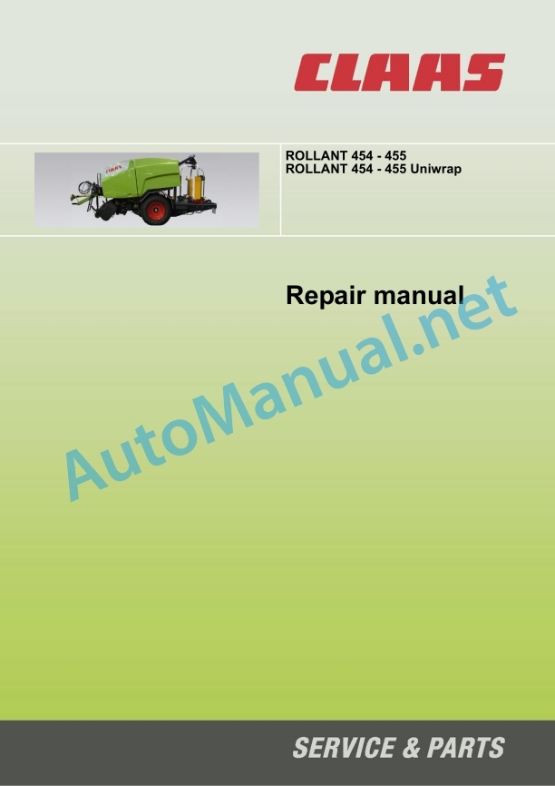
Claas Rollant 455 Uniwrap (750) Balers Repair Manual EN
$300.00
- Model: Rollant 455 Uniwrap (750) Balers
- Type Of Manual: Repair Manual
- Language: EN
- Format: PDF(s)
- Size: 38.4 MB
File List:
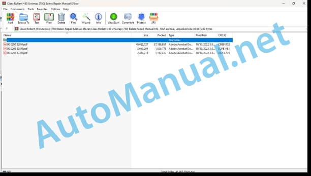
00 0290 528 0.pdf
00 0292 303 0.pdf
00 0292 333 0.pdf
00 0290 528 0.pdf:
Introduction
General Information
Using the manual
Validity of manual
General repair instructions
Specifications
Reason of damage
Spare parts
Welding Work
Tensioning the steel roller chains
Taper ring fasteners
Gib head key joints
Self-locking bolts with micro-encapsulated adhesive
Liquid locking compound
Lock collar bearing
Adapter sleeve bearing
Ferrule fittings on hydraulic lines
Progressive ring fittings on hydraulic lines
Taper fittings on hydraulic lines
Hydraulic hoses
Some advice for speedy and correct repair work
Torque settings
Tightening torques for metric standard threads
Tightening torques for metric fine threads
Tightening torques for hydraulic screw fittings with ferrule according to DIN 3861
Tightening torques for hydraulic screw fittings and air conditioner fittings with a sealing cone and O-ring DIN 3865
Tightening torques for hydraulic male connector DIN 3901
Tightening torques for direction-adjustable hydraulic male connectors ISO 6149-2 / ISO 11926-2 (3)
Tightening torques for hydraulic swivelling screw fittings
Tightening torques for hollow screws DIN 7643
Tightening torques of brake line screw fittings
Tightening torques for screw thread clamps
Wheel tightening torques
Specifications
Lubricants
CCN explanations
CCN (CLAAS Component Number)
Electric system standard
Hydraulic system standard
General information
Important notice
Identification of warning and danger signs
General safety and accident prevention regulations
Leaving the machine
Adjustment and maintenance work
Danger of injury due to escaping hydraulic liquid
Pressure accumulator
First aid measures
Jack up the machine
Putting the machine out of action
03 Chassis
03 10 Axle
Overview of stub axle
Removing a stub axle
Fitting a stub axle
Removing a wheel hub
Fitting a wheel hub
04 10 Service brakes
Overview of brake mechanism
Removing a brake
Fitting a brake
Overview of pneumatic brake chamber
Removing a pneumatic brake chamber
Fitting a pneumatic brake chamber
Overview of pneumatic brake system
Removing the compressed air tank
Fitting the compressed air tank
Overview of hydraulic brake cylinder
Removing a hydraulic brake cylinder
Fitting a hydraulic brake cylinder
04 15 Parking brake
Overview of parking brake
Setting the parking brake
09 Hydraulic system
09 00 Hydraulic system General points
Hydraulic system damage
General rules
09 20 Valves
Overview of ROLLANT 455 and 455 Uniwrap baler hydraulic block
Main block (1) – Overview A
Main block (1) – Overview B
Electric block (2) – Overview
Control block (3) – Overview A
Control block (3) – Overview B
Overview of ROLLANT 454 and 454 Uniwrap baler hydraulic block
Control block (3) – Overview A
Control block (3) – Overview B
Overview of wrapper hydraulic block WITH anti-roll
Wrapper main block (1) – Overview A
Wrapper main block (1) – Overview B
Wrapper main block (1) – Overview C
Flow divider (2) – Overview
Wrapper control block WITH anti-roll (3) – Overview
Cutter flow divider (4) – Overview
Wrapper controlled valves block (5) – Overview
Overview of wrapper hydraulic block WITHOUT anti-roll
Wrapper control block WITHOUT anti-roll (3) – Overview
Removing the baler hydraulic block
Fitting the baler hydraulic block
Removing the wrapper hydraulic block
Fitting the wrapper hydraulic block
Removing / Fitting a solenoid valve
Removing / Fitting a proportional solenoid valve
Removing / Fitting valve (7032)
Removing / Fitting valve (7060)
Calibrating the wrapping arm speed
Calibrate the hydraulic system protection valve (7190)
09 20 Special tool, valves
Checking and then setting the pressure limit valve
Extracting the hydraulic block components
Removing the seals and rings
10 Electric / electronic equipment
10 00 Special tools for electric system, general
Replacing terminals and connectors in the electric system
Diagnosis of electric components
Diagnosis of electric components
10 10 Central electric system
Overview of emergency stop U025
Removing the emergency stop
Fitting the emergency stop
10 12 Sensors / Modules
Overview of module A023
Removing the module
Fitting the module
Overview of tailgate position detector
Removing the sensor assembly
Disassembling the sensor assembly
Assembling the sensor assembly
Fitting the sensor assembly
Setting the sensor assembly
21 Feeder unit
21 25 Rotor
Overview of cutting frame sensor B067
Removing the cutting frame sensor
Fitting the cutting frame sensor
Setting the cutting frame sensor
Overview of cutting frame
Removing the cutting frame assembly
Disassembling the cutting frame assembly
Assembling the cutting frame assembly
Fitting the cutting frame assembly
Removing the pivoting floor
Fitting the pivoting floor
Overview of rotor scraper
Removing the rotor scraper
Fitting the rotor scraper
Overview of the blade frame
Removing a blade activation shaft
Fitting a blade activation shaft
Removing the blade tilting shaft
Disassembling a tilting lever
Assembling a tilting lever
Fitting the blade tilting shaft
Removing the blade locking shaft
Disassembling the blade locking shaft
Assembling the blade locking shaft
Fitting the blade locking shaft
Overview of rotor drive
Removing the rotor drive chain
Fitting the rotor drive chain
Removing the motor gear
Fitting the motor gear
Removing the rotor drive gear
Fitting the rotor drive gear
Removing the idle gear
Fitting the idle gear
Removing the tensioning gear
Disassembling the tensioning gear
Assembling the tensioning gear
Fitting the tensioning gear
Setting the rotor chain tension
Overview of blade activation cylinders
Removing the right-hand blade activation cylinder
Fitting the right-hand blade activation cylinder
Removing the left-hand blade activation cylinder
Fitting the left-hand blade activation cylinder
Overview of cutting frame cylinders
Removing the cutting frame cylinders
Fitting the cutting frame cylinders
Overview of roller 1
Removing roller 1
Fitting roller 1
46 Tying system
46 15 Net tying
Overview of net tying structure
Removing the net tying structure
Disassembling the net tying structure
Assembling the net tying structure
Fitting the net tying structure
Overview of box and net brake
Removing the box and net brake
Disassembling the box and net brake
Assembling the box and net brake
Fitting the box and net brake
Overview of cutter resetting spring cylinder
Removing the resetting cylinder
Disassembling the resetting cylinder
Assembling the resetting cylinder
Fitting the resetting cylinder
Overview of net runner
Removing the net runner
Fitting the net runner
View of tying system rubber roller drive
Removing the tying system drive
Fitting the tying system drive
View of tying clutch drive
Removing the clutch drive
Fitting the clutch drive
47 Bale wrapper
47 05 Tilting box
Overview of tilting box position sensor B211
Removing the tilting box sensor B211
Fitting the tilting box sensor B211
Setting the tilting box sensor B211
Overview of tilting box
Removing the tilting box
Disassembling the tilting box
Assembling the tilting box
Fitting the tilting box
Operating check on box bale presence sensor B102
Overview of tilting box hydraulic hoses
Overview of tilting box hydraulic cylinder
Removing the tilting box hydraulic cylinders
Fitting the tilting box hydraulic cylinders
47 10 Chassis
Overview of wrapper chassis
Removing the wrapper chassis
Fitting the wrapper chassis
47 15 Wrapping table
Overview of wrapping table sensor B210
Removing the wrapping table sensor
Fitting the wrapping table sensor
Setting the wrapping table sensor B210
Overview of wrapping table
Removing the wrapping table
Disassembling the wrapping table
Removing the bale twister supports (according to equipment)
Assembling the wrapping table
Fitting the bale twister supports (according to equipment)
Fitting the wrapping table
Overview of wrapping table rollers
Removing the wrapping table rollers
Fitting the wrapping table rollers
Overview of wrapping table belts
Removing the wrapping table belts
Fitting the wrapping table belts
Overview of wrapping table hydraulic hoses
Overview of wrapping table hydraulic cylinders
Removing the wrapping table hydraulic cylinders
Fitting the wrapping table hydraulic cylinders
Overview of wrapping table drive
Removing the wrapping table drive
Fitting the wrapping table drive
47 20 Bale twister
Overview of bale twister
Disassembling the bale twister
Assembling the bale twister
47 25 Support clamp
Overview of support clamp
Removing the support clamp
Fitting the support clamp
47 30 Wrapping arm
Overview of wrapping arm
Removing the wrapping arm
Fitting the wrapping arm
Overview of safety hoop
Removing the safety hoop
Fitting the safety hoop
Disassembling the safety hoop
Assembling the safety hoop
Setting the safety hoop stop
Setting the safety hoop activation sensor (Z091)
Removing the original position sensor (B106)
Fitting the original position sensor (B106)
Setting the original position sensor (B106)
Operating check on wrapping arm original position sensor (B106)
Overview of wrapping arm hydraulic hoses
Overview of wrapping arm hydraulic drive
Removing the wrapping arm hydraulic drive
Fitting the wrapping arm hydraulic drive
47 35 Drawing device
Overview of drawing device
Removing the drawing device
Disassembling the drawing device
Assembling the drawing device
Fitting the drawing device
Wrapping film unwinding sensors B109 operating check
47 40 Film cutter
Overview of film cutter
Overview of film cutter hydraulic hoses
Removing the film cutter
Disassembling the film cutter
Assembling the film cutter
Fitting the film cutter
Overview of film cutter cylinder
Removing the film cutter cylinder
Fitting the film cutter cylinder
47 45 Film roller holder
Overview of film roller holder
Removing the film roller holder
Fitting the film roller holder
Overview of film roller holder hydraulic hoses
Overview of film roller holder cylinder
Removing the film roller holder cylinder
Fitting the film roller holder cylinder
60 Crop output
60 40 Bale chute
Overview of bale discharge guide
Removing the bale discharge guide assembly
Fitting the bale discharge guide assembly
Overview of bale discharge guide hoses
Overview of bale discharge guide cylinder assembly
Removing the bale discharge guide hydraulic cylinders
Fitting the bale discharge guide hydraulic cylinders
75 Central lubrication system
75 10 Control valves
Overview of control valves
Control valve 1
Control valve 2, ROLLANT 454 and 454 Uniwrap
Control valve 2, ROLLANT 455 and 455 Uniwrap
Control valve 3, ROLLANT 454 and 454 Uniwrap
Control valve 3, ROLLANT 455 and 455 Uniwrap
Main control valve
75 15 Lubrication system / pipes
Overview of automatic lubrication pump
Removing the lubrication pump
Fitting the lubrication pump
Setting the lubrication pump flow
Removing the pump activation stop
Disassembling the pump activation stop
Assembling the pump activation stop
Setting the pump activation stop
Fitting the pump activation stop
Overview of chain lubrication system
Removing the chain lubrication pump
Disassembling the chain lubrication pump
Assembling the chain lubrication pump
Fitting the chain lubrication pump
Setting the chain lubrication pump
CCN (CLAAS Component Number)
00 0292 303 0.pdf:
ROLLANT 454 UNIWRAP
ROLLANT 455 UNIWRAP
Content assignment
Spis tre��ci
Vsebinsko kazalo
Table of Contents
1 Bendrieji nuidomai
1.2 Reikalingo’s conditions
1.3 Ma��ino’s paper preparation
Hidraulinis is filtered
Nuimti valva����-ribotuv��
Functional AR (CCN 7068) valdymas
Hidraulinio slukato tikrinimas
Alyvo’s temperature
1.4 Veikimo is tested
2 Nustatymai
2.1 Stalo / peties vejdjo santykio sureguliavimas (atk��rimas)
2.2 Maksimalaus vyniojimo peties sukimosi vejdjos numisma
6 stages stages
2.3 Tikrinimas ir bandymas
1 General informaaf
1.3 Preparing the machine
Hydraulic filter
Dismantle de begrenzerklep (depends on configuration)
8)
Controle van de hydraulic branch part van de achterklep
Oil temperature
1.4 Test van de werking
2 The appointment
2.1 Adjustment of the table/arm ratio (overlapping)
2.2 Adjustment of the maximum speed of the winding arms
2.3 Control a test
1 General tips
1.1 Security
1.2 Before you begin
1.3 Preparation of the machine
Hydraulic filter
Remove the restriction valve (depending on configuration)
Checking the OR function (CCN 7068)
Checking the tailgate’s hydraulic lock
Oil temperature
1.4 Functional test
2 Settings
2.1 Setting the ratio between the speed of the packing table and the packing arm (coverage)
2.2 Setting the packing arm’s maximum speed
2.3 Control and testing
1 General instructions
1.1 Bezpiecze��stwo
1.2 Introduction
1.3 Preparing the machine
Filter hydraulic
Wymontowa�� zaw��r redukcyjny (dependenie od konfigurazione)
Control function WYBORU (CCN 7068)
Kontrola sy��wnika hydraulicznegemperature
1.4 Test operation
2 Settings
2.1 Regulation of speed control
2.2 Regulation of the maximum speed of the ramie owijaj��cego
2.3 Kontrola i pr��ba ��anje
1 Splosna warn
1.1 Security
1.2 Preliminary requirements
1.3 Prepare the garment
Hydraulic filter
Despitetev reducirnega ventila (glede na konfiguratijo)
Kontrola wo��ka za sz����y funksi (CCN 7068)
Kontrola hydraulicne blokade last pokro
Oil temperature
1.4 Probe’s action
2 Settings
2.1 Setting the speed of the podesta in roke (prekrivije)
2nd st stage
2.2 Nes 7th stage
2.3 Control in test
1 General instructions
1.1 Security
1.2 Preparations
1.3 Prepare the machine
Hydraulic filter
Remove the throttle valve (depending on configuration)
Checking the OR function (CCN 7068)
Checking the tailgate hydraulic lock
Oil temperature
1.4 Functional test
2 Settings
2.1 Setting the speed ratio between table and arm (overlap the wrapping arm
2.3 Control and test
Dalykin�� rodykle
Alphabetical index
00 0292 333 0.pdf:
ROLLANT 454 UNIWRAP
ROLLANT 455 UNIWRAP
Content assignment
Eat content
Vsebinsko kazalo
Index of contents
1 Bendrieji nuidomai
1.2 eikalingo’s conditions
2 Nustatymai
2.1 Ma��ino’s paper preparation
2.2 Stalo / peties vejdjo santykio sureguliavimas (atk��rimas)
5 ssimalaus vyniojimo peties sukimosi vejsto namistamiya
2.4 Tikrinimas ir bandymas
Po bandymo
1 General information
1.1 Security
2 The appointment
2.1 Preparing the machine
2.2 Adjustment of the table/arm speed ratio (overlap)
2.3 Adjustment of the maximum speed of the winding arm
2.4 Control a test
1 General tips
1.1 Security
1.2 Before You Begin
2 Settings
2.1 Preparation of the machine
2.2 Setting the ratio between the speed of the packing table and the packing arm (coverage)
2.3 Setting the packing arm’s maximum speed
2.4 Control and testing
After testing
ns
1.1 Bezpiecze��stwo
1.2 Prerequisites
2 Ustavyane
2.1 Preparing the machine
2.2 Regulacja nadzicka ve��i�� sto��u / ramienia (zak��adka)
2.3 Regulacja maximum speed ramienia owijaj��cego
2.4 Control of trial operations
Po przeprowadzeniu pr��by
1 General warnings
1.1 Security
1.2 Prerequisites
2 Settings
2.1 Prepare the machine
2.2 Setting the speed of the podesta in roke (prekrivije)
2.3 Setting the maximum speed of the vehicle
2.4 Control in test
After testing
1 General instructions
1.1 Security
1.2 Preparations
2 Settings
2.1 Prepare the machine
2.2 Setting the speed ratio between table and arm (overlapping)
2.3 Setting the maximum speed of the filler arm
John Deere Repair Technical Manual PDF
John Deere Diesel Engines PowerTech 4.5L and 6.8L – Motor Base Technical Manual 07MAY08 Portuguese
John Deere Repair Technical Manual PDF
John Deere Repair Technical Manual PDF
John Deere Repair Technical Manual PDF
John Deere Repair Technical Manual PDF
John Deere Application List Component Technical Manual CTM106819 24AUG20
John Deere Repair Technical Manual PDF
John Deere Repair Technical Manual PDF
John Deere Repair Technical Manual PDF
John Deere Repair Technical Manual PDF


