Skip to content
Auto ManualAuto Manual
  • Login
  • $0.00
    • No products in the cart.

      Return to shop

  • Cart

    No products in the cart.

    Return to shop

  • Category
  • Menu
  • About us
  • Shop
  • News
  • Contact Us
  • John Deere
  • Claas
    • Claas Assembly Instruction PDF
    • Claas Operator Manual PDF
    • Claas Repair Manual PDF
    • Claas Service Information PDF
    • Claas Technical System PDF
  • Grove
  • Jungheinrich
  • Komatsu
  • Kubota
  • Manitowoc
  • New Holland
  • Yale
  • Yanmar
Support
Email
admin@automanual.net
Follow us
Home / Claas / Claas Operator Manual PDF
claas rollant 540 rc rf j03 balers operator manual en 1
claas rollant 540 rc rf j03 balers operator manual en 2
claas rollant 540 rc rf j03 balers operator manual en 3
claas rollant 540 rc rf j03 balers operator manual en 4
claas rollant 540 rc rf j03 balers operator manual en 5
claas rollant 540 rc rf j03 balers operator manual en 2
claas rollant 540 rc rf j03 balers operator manual en 3
claas rollant 540 rc rf j03 balers operator manual en 4
claas rollant 540 rc rf j03 balers operator manual en 5

Claas Rollant 540 Rc Rf (J03) Balers Operator Manual EN

$50.00

  • Model: Rollant 540 Rc Rf (J03) Balers
  • Type Of Manual: Operator Manual
  • Language: EN
  • Format: PDF(s)
  • Size: 141 MB
Category: Claas Operator Manual PDF Tag: Agricultural
Product Categories
  • All Product (0)
  • Alo (0)
    • Alo Service Manual PDF (0)
  • Bomag (3660)
    • Bomag Operator Manual PDF (0)
    • Bomag Other Manual PDF (0)
    • Bomag Parts Manual PDF (0)
    • Bomag Repair Manual PDF (0)
    • Bomag Service Manual PDF (1159)
    • Bomag Spare Parts Catalogue PDF (2501)
  • Briggs and Stratton (0)
    • Briggs and Stratton Repair Manual PDF (0)
  • CASE (0)
    • CASE Operator Manual PDF (0)
    • CASE Other Manual PDF (0)
    • CASE Parts Catalog PDF (0)
    • CASE Service Manual PDF (0)
    • CASE Workshop Manual PDF (0)
  • Claas (6622)
    • Claas Assembly Instruction PDF (741)
    • Claas Operator Manual PDF (2393)
    • Claas Repair Manual PDF (1660)
    • Claas Service Information PDF (20)
    • Claas Technical System PDF (1808)
  • Clark (0)
    • Clark Operator Manual PDF (0)
    • Clark Other Manual PDF (0)
    • Clark Parts Manual PDF (0)
    • Clark Service Manual PDF (0)
    • Clark Workshop Manual PDF (0)
  • CMI Corporation (0)
    • CMI Corporation Parts Manual PDF (0)
    • CMI Corporation Service Manual PDF (0)
  • CNH (0)
    • CNH Operator Manual PDF (0)
    • CNH Repair Manual PDF (0)
    • CNH Service Manual PDF (0)
  • Doosan (0)
    • Doosan Operator Manual PDF (0)
    • Doosan Service Manual PDF (0)
  • Dynapac (0)
    • Dynapac Spare Parts Catalogue PDF (0)
  • Eaton Hydraulics Division (0)
    • Eaton Hydraulics Division Repair Manual PDF (0)
  • Fiat Hitachi (0)
    • Fiat Hitachi Service Manual PDF (0)
  • Fiatagri (0)
    • Fiatagri Operator Manual PDF (0)
    • Fiatagri Service Manual PDF (0)
    • Fiatagri Workshop Manual PDF (0)
  • Fiatallis (0)
    • Fiatallis Operator Manual PDF (0)
    • Fiatallis Other Manual PDF (0)
    • Fiatallis Repair Manual PDF (0)
    • Fiatallis Service Manual PDF (0)
  • Flexi Coil (0)
    • Flexi Coil Repair Manual PDF (0)
    • Flexi Coil Service Manual PDF (0)
  • Ford New Holland (0)
    • Ford New Holland Operator Manual PDF (0)
    • Ford New Holland Other Manual PDF (0)
    • Ford New Holland Repair Manual PDF (0)
    • Ford New Holland Service Manual PDF (0)
  • FPT Powertrain Technologies (0)
    • FPT Powertrain Technologies Service Manual PDF (0)
  • Grove (3764)
    • Grove Parts List PDF (3764)
  • Hesston (0)
    • Hesston Operator Manual PDF (0)
  • HINO (1)
  • Hypac (0)
    • Hypac Spare Parts Catalogue PDF (0)
  • IMT (198)
  • John Deere (580)
    • John Deere Operation and Test Manual PDF (24)
      • John Deere Wiring Diagrams PDF (24)
    • John Deere Parts Catalog PDF (371)
    • John Deere Repair Technical Manual PDF (165)
  • Jungheinrich (3746)
    • Jungheinrich Spare Parts Manual PDF (3744)
  • Kemper (0)
    • Kemper Repair Manual PDF (0)
  • Kobelco (0)
    • Kobelco Repair Manual PDF (0)
    • Kobelco Service Manual PDF (0)
  • Kohler (0)
    • Kohler Service Manual PDF (0)
  • Komatsu (9889)
    • Komatsu Operation and Maintenance Manual PDF (4958)
    • Komatsu Other Manual PDF (0)
    • Komatsu Parts Manual PDF (2021)
    • Komatsu Service Manual PDF (64)
    • Komatsu Shop Manual PDF (2846)
  • Krupp (58)
    • Krupp Parts List PDF (58)
  • Kubota (2290)
    • Kubota Operators Manual PDF (95)
    • Kubota Other Manual PDF (10)
    • Kubota Parts Manual PDF (1817)
    • Kubota Service Manual PDF (9)
    • Kubota Workshop Manual PDF (359)
  • Liebherr (2)
  • Linde (0)
    • Linde Operator Manual PDF (0)
    • Linde Parts Manual PDF (0)
    • Linde Workshop Manual PDF (0)
  • Manitowoc (998)
    • Manitowoc Parts Manual PDF (998)
  • Miller (0)
    • Miller Repair Manual PDF (0)
    • Miller Service Manual PDF (0)
  • New Holland (1)
    • New Holland Operator Manual PDF (0)
    • New Holland Parts Catalog PDF (0)
    • New Holland Repair Manual PDF (0)
    • New Holland Service Manual PDF (0)
    • New Holland Workshop Manual PDF (0)
    • Service Manual PDF (1)
  • Other Language (0)
  • Other Manual (0)
    • Superior Engineering Service Manual PDF (0)
  • Porsche (5)
  • Sperry New Holland (0)
    • Sperry New Holland Operator Manual PDF (0)
    • Sperry New Holland Parts Catalog PDF (0)
    • Sperry New Holland Service Manual PDF (0)
  • Stehr (0)
    • Stehr Spare Parts Catalogue PDF (0)
  • Stow (0)
    • Stow Spare Parts Catalogue PDF (0)
  • TCM (1)
  • Terex (0)
    • Terex Service Manual PDF (0)
  • Versatile (0)
    • Versatile Operator Manual PDF (0)
    • Versatile Service Manual PDF (0)
  • Yale (585)
    • Yale Service Manual PDF (585)
  • Yanmar (0)
    • Yanmar Service Manual PDF (0)
  • Zahnradfabrik (0)
    • Zahnradfabrik Repair Manual PDF (0)
Recently Viewed Products
  • Claas Scorpion 635 (K30) Telehandlers Operator Manual EN Claas Scorpion 635 (K30) Telehandlers Operator Manual EN $50.00
  • Claas Scorpion 6030 (K20) Telehandlers Operator Manual ES Claas Scorpion 6030 (K20) Telehandlers Operator Manual ES $50.00

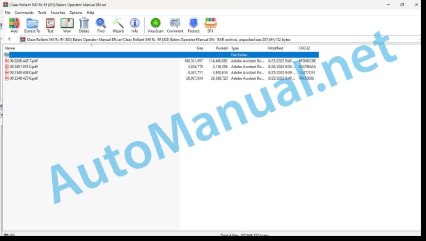
File List:

00 0288 445 7.pdf
00 0301 051 0.pdf
00 2348 408 0.pdf
00 2348 427 0.pdf

00 0288 445 7.pdf:

ROLLANT 540 RFROLLANT 540 RCROLLANT 540 RC Comfort
Table of contents
1 Introduction
1.1 General information
1.1.1 Manual validity
1.1.2 Information about this Operator’s Manual
1.1.3 Symbols and notes
1.1.4 Optional equipment
1.1.5 Qualified specialist workshop
1.1.6 Maintenance notes
1.1.7 Notes on warranty
1.1.8 Spare parts and technical questions
1.2 Intended use
1.2.1 Using in line with intended usage
1.2.2 Reasonably foreseeable misuse
2 Safety
2.1 Identifying warnings
2.1.1 Hazard signs
2.1.2 Signal word
2.2 Safety rules
2.2.1 Importance of Operator’s Manual
2.2.2 Observing safety decals and warnings
2.2.3 Requirements for all persons working with the machine
2.2.4 Children in danger
2.2.5 Hazard areas
2.2.6 Presence between tractor and machine
2.2.7 Persons riding on the machine
2.2.8 Hitching the tractor to the machine
2.2.9 Danger of injury from rotating shafts
2.2.10 Structural alterations
2.2.11 Optional equipment and spare parts
2.2.12 Controlling the tractor when it is running
2.2.13 Operation only after proper putting into operation
2.2.14 Technical condition
2.2.15 Danger from damage to the machine
2.2.16 Complying with technical limit values
2.2.17 Danger from continued running of machine parts
2.2.18 Keeping safety devices functional
2.2.19 Personal protective equipment
2.2.20 Wearing suitable clothing
2.2.21 Removing dirt and loose objects
2.2.22 Preparing the machine for road travel
2.2.23 Risks when driving on the road and in the field
2.2.24 Parking the machine safely
2.2.25 Unsupervised parking
2.2.26 Unsuitable operating materials
2.2.27 Safe handling of operating and auxiliary utilities
2.2.28 Environmental protection and disposal
2.2.29 Fire prevention
2.2.30 Highly dangerous electric shock from the overhead power lines
2.2.31 Electrocution by electrical system
2.2.32 Pressurised fluids
2.2.33 Compressed air
2.2.34 Hot surfaces
2.2.35 Working on machine only after shutting it down
2.2.36 Maintenance work and repairs
2.2.37 Raised machine parts and loads
2.2.38 Risks related to welding work
2.3 Safety decals
2.3.1 Layout of safety decals
2.3.2 Location of safety stickers
3 Machine description
3.1 Existing models
3.1.1 Machine description
3.2 Overview and functions
3.2.1 Left-hand side
3.2.2 Right-hand side
3.2.3 Roller identification
3.3 Safety equipment
3.3.1 Indicator lights
3.3.2 Reflective equipment*
3.3.3 Jack stand
3.3.4 Chocks
3.3.5 Retaining cable*
3.3.6 Parking brake*
3.3.7 Locking the tailgate
3.3.8 Locking the film guiding rollers*
3.3.9 Locking the pick-up
3.3.10 Extinguisher*
3.4 Working and service areas
3.4.1 General points
3.4.2 Front section of the baler
3.5 Identification plates and identification number
3.5.1 Replacement parts and technical information
3.5.2 Identification number or VIN code
3.5.3 Machine identification plate
Identification plate for a machine with European certification
Identification plate for a machine without European certification
Identification plate for countries in the Customs Union (Belarus, Kazakhstan, Russia)
3.5.4 Drawbar identification plate*
3.5.5 Axle identification plate
3.6 Information on the machine
3.6.1 Location of information stickers
3.7 General operating principle
3.7.1 Baling cycle
3.8 Control terminal
3.8.1 CEMIS 700*
3.8.2 COMMUNICATOR*
3.8.3 OPERATOR*
3.8.4 ISOBUS connection*
3.9 Coupling frame
3.9.1 Types of hitch
3.10 Transmission and drive
3.10.1 Power transmission
3.10.2 Main drive
3.10.3 Pick-up drive
3.10.4 Rotor drive*
3.10.5 Drive chains
3.11 Crop feeding
3.11.1 Pick-up
3.11.2 Pick-up wheels
3.11.3 Crop guard*
3.11.4 Short crop plate*
3.11.5 Roller crop press*
3.11.6 Double roller crop press*
3.12 Feeder unit
3.12.1 Rotor
3.12.2 Rotor chassis with pivoting floor*
3.12.3 ROTO CUT cutting unit*
3.13 Baling system
3.13.1 Bale chamber and rollers
3.13.2 MPS (Maximum Pressure System or oscillating segment)
3.13.3 Baling cycle
3.14 Tying system
3.14.1 Tying categories and types
3.14.2 Standard tying
3.14.3 Comfort tying
3.14.4 Net tying
3.14.5 Film tying
3.14.6 Tying setting
3.14.7 Twine box*
3.14.8 Spare net storage mounting*
3.14.9 Spare film / net storage mounting*
3.14.10 Net box*
3.14.11 Film / net box*
3.14.12 Deflector
3.15 Bale discharge
3.15.1 Bale ramp
3.16 Lubrication system (oil)
3.16.1 Automatic chain lubrication
3.17 Lubrication system (grease)
3.17.1 Manual lubrication
3.17.2 Manual central lubrication*
3.17.3 Electric automatic central lubrication*
3.18 Brake
3.18.1 General points
3.18.2 Hydraulic brakes*
3.18.3 Active hydraulic brakes*
3.18.4 Pneumatic brakes*
3.19 Hydraulic system
3.19.1 Baler hydraulic block
Standard hydraulics*
Comfort hydraulics* with continuous circulation
3.19.2 Hydraulic circuit filter
3.19.3 Continuous hydraulic circulation*
3.19.4 Load-Sensing*
3.20 Equipment
3.20.1 Ladder
3.20.2 Step
3.20.3 Electronic module
3.20.4 Anti-theft device*
3.20.5 Work lighting*
3.20.6 Axle elevations
4 Operating and display elements
4.1 CEMIS 700
4.1.1 Presentation
4.1.2 Description of the CEMIS 700 menus
menu
menu
menu
menu
menu
menu
menu
4.1.3 Description of the CEMIS 700 menus
menu
menu
menu
menu
menu
menu
menu
4.2 COMMUNICATOR II
4.2.1 Presentation
4.3 OPERATOR
4.3.1 Presentation
4.4 ISOBUS terminal
4.4.1 Presentation
4.4.2 General points
5 Technical specifications
5.1 Baler
5.1.1 Dimensions
5.1.2 Weight
5.1.3 Hitching
5.1.4 Universal drive shaft
5.1.5 Feeding and baling
5.1.6 Tying device
5.1.7 Wheels
5.1.8 Hydraulic circuit
5.1.9 Bolt tightening torques
5.1.10 Braking
5.1.11 Greasing and lubrication
5.1.12 Noise level
5.2 Safety devices
5.2.1 Shear bolt
5.2.2 Cut-out clutch
5.3 Operating utilities
5.3.1 Lubricants
5.3.2 Tying twine
5.3.3 Tying net
5.3.4 Tying film
5.4 Tractor
5.4.1 Power required
5.4.2 Maximum authorised weight of the towing vehicle
5.4.3 Hitching
5.4.4 Power take-off
5.4.5 Electrical connections
5.4.6 Hydraulic connections
Standard hydraulics*
Comfort hydraulics* with continuous circulation
5.4.7 Hydraulic oil and circuit
5.4.8 Braking
6 Machine preparation
6.1 Switching off and securing the machine
6.1.1 Stopping and securing the tractor and machine
6.2 Adapting the tractor
6.2.1 Checking the protective guard on the tractor PTO shaft
6.2.2 Configuring the tractor air brake system
6.2.3 Fitting the CEMIS 700*
6.2.4 Installing the COMMUNICATOR II*
6.2.5 Installing the OPERATOR*
6.2.6 Battery cable*
6.3 Adapting the machine
6.3.1 Recommendations
6.3.2 Adapting clevis hitch / swinging drawbar
6.3.3 Overlap of the universal drive shaft
6.3.4 Adapting the length of the universal drive shaft
6.4 Hitching the machine
6.4.1 Retaining cable*
6.4.2 Locking the hitch
6.4.3 Universal drive shaft safety advice
6.4.4 Fitting the universal drive shaft
6.4.5 Hydraulic connections
6.4.6 Machine with standard hydraulics*
6.4.7 Machine with comfort hydraulics* not equipped with Load-Sensing
6.4.8 Machine with comfort hydraulics* equipped with Load-Sensing and tractor equipped with Load-Sensing
6.4.9 Machine with comfort hydraulics* equipped with Load-Sensing and tractor not equipped with Load-Sensing
6.4.10 Hydraulic brakes*
6.4.11 Active hydraulic brakes*
6.4.12 Pneumatic brake*
6.4.13 Identifying the electrical cables
6.4.14 Lighting
6.4.15 Power supply for the baler and the CEMIS 700
6.4.16 Power supply for the baler and the COMMUNICATOR*
6.4.17 Power supply for the baler and the OPERATOR*
6.4.18 Power supply for the baler using the ISOBUS cable*
6.5 Preparing fieldwork
6.5.1 Pick-up wheels
Setting the working position of the pick-up wheels
Setting the transport position of the pick-up wheels
6.5.2 Folding pivoting pick-up wheels*
6.5.3 Pick-up height
6.5.4 Crop guard
6.5.5 Roller crop press*
6.5.6 Double roller crop press*
6.6 Twine tying
6.6.1 Twine quality
6.6.2 Preparation
6.6.3 Fitting the twine
6.6.4 Selecting twine tying*
6.7 Net tying
6.7.1 Quality of the net
6.7.2 Preparation
6.7.3 Fitting a net roller
Fitting the net roller in the net box
Centring the net roller in the net box
6.7.4 Fitting the net
6.7.5 Net tension
6.7.6 Selecting standard net tying*
6.8 Film / net tying
6.8.1 Quality of the net
6.8.2 Tying film quality
6.8.3 Fitting the film* or net* roller
6.8.4 Fitting the film
6.8.5 Fitting the net
6.8.6 Film stretching / net tension – Setting the tying brake
6.9 Bale discharge
6.9.1 General points
6.9.2 Fitting the bale ramp
Removing the bale ramp
6.10 Cutting unit
6.10.1 Safety advice
6.10.2 Checking
6.10.3 Fitting the knives*
6.10.4 Fitting the dummy knives*
6.10.5 Unused knives and dummy knives*
6.11 Loading the machine
6.11.1 Lifting points
6.11.2 Lifting
6.11.3 Lashing the baler
7 Operation
7.1 General information
7.1.1 Baler user
7.1.2 Opening the flaps, hoods and covers
Side flaps
Left pick-up housing
Upper cover
7.1.3 Raising / lowering the pick-up
7.1.4 Activating / deactivating the ROTO CUT knives*
7.1.5 Raising / lowering the pivoting floor*
7.1.6 Opening / closing the tailgate
7.1.7 Resetting the tying knife
7.2 Travelling with the baler
7.2.1 Checking the equipment
7.2.2 Preparing for transportation
7.2.3 Travelling on the road
7.2.4 Arriving at the field
7.2.5 Driving in fields
7.2.6 Parking
7.3 Before each usage
7.3.1 Reminders
7.3.2 Universal drive shaft
7.3.3 Baler maintenance
7.3.4 Checking the equipment
7.3.5 Periods of very hot weather
7.4 Commissioning in the field
7.4.1 User advice
7.4.2 Operational guidelines for film tying*
Film rollers
Baling / tying parameters
Bale coverage
Bale exiting the bale chamber
Extreme conditions
7.4.3 Starting the machine
7.5 Pick-up
7.5.1 Important
7.6 Baling
7.6.1 MPS* (Maximum Pressure System or oscillating segment)
Settings
Deactivating the MPS
7.7 Tying
7.7.1 Selecting the tying type*
Net / twine* tying
Film / net* tying
7.7.2 Setting the number of twine wraps
7.7.3 Setting the number of net wraps
Comfort net tying*
Standard net tying*
Setting system
Position of the eccentric stop
Setting the number of net wraps
7.7.4 Setting the number of film wraps*
Comfort film tying*
7.7.5 Replacing the roller of film* or net* during tying
7.8 Bale parameters
7.8.1 Setting the bale parameters
Baling pressure
Comfort machines*
Standard machines*
Recommendations
MPS* (Maximum Pressure System or oscillating segment)
Standard twine / net tying*
Twine tying
Net tying
Comfort net tying*
Film / net tying*
Film tying
Net tying
7.9 CEMIS 700
7.9.1 Display and navigation
7.9.2 Using the virtual keypad
7.9.3 menu
7.9.4 Job name
7.9.5 Baling-tying cycle
Baling-tying process steps (standard machines)
Baling-tying process steps (Comfort machines)
7.9.6 menu
Setting the usage parameters (standard machines)
Usage parameters (standard machines)
Selecting the tying type*
Tying delay
Beep when approaching the end of the bale
Bale ramp
Automatic lubrication interval*
Setting the usage parameters (Comfort machines)
Usage parameters (Comfort machines)
Tying delay
Film tying*
Net tying
Setting the tying delay
Number of film* or net* wraps
Selecting the tying type*
Film stretching
Net tension
Baling pressure
Number of ROTO CUT knives with selection*
Automatic tailgate opening
Opening the tailgate before tying
Automatic ROTO CUT* knife cleaning
Beep when approaching the end of the bale
Bale ramp
Automatic lubrication interval*
7.9.7 Selecting the tying type*
Standard machines
Comfort machines
7.9.8 Automatic central lubrication*
7.9.9 Baling pressure
7.9.10 Manual tying start
7.9.11 Tying delay
7.9.12 ROTO CUT* / ROTO FEED* / Pivoting floor*
Standard machines
Activating / deactivating the ROTO CUT knives
Raising / lowering the pivoting ROTO CUT floor*
Raising / lowering the pivoting ROTO FEED floor*
Comfort machines
Activating / deactivating the ROTO CUT knives
Raising / lowering the pivoting ROTO CUT floor
7.9.13 Opening the tailgate
Standard machines
Manual tailgate opening / closing
Comfort machines
Automatic tailgate opening / closing
Manual tailgate opening / closing
7.9.14 Faults
7.9.15 DTC Faults
7.9.16 Faults
7.9.17 Monitoring the sensors and actuators
Sensors and actuators
Standard machines
Comfort machines
7.10 COMMUNICATOR II
7.10.1 General points
7.10.2 Functions which can be assigned to softkeys
7.11 Unblocking the baler
7.11.1 How can blockages be avoided?
7.11.2 Safety advice
7.11.3 Unblocking the pick-up
7.11.4 Unblocking the pick-up with double roller crop press*
7.11.5 Unblocking the rotor*
7.12 After use
7.12.1 Reminders
7.12.2 Securing the baler
7.12.3 Daily checks
7.12.4 Daily cleaning
7.13 Unhitching the machine
7.13.1 Retaining cable*
7.13.2 Unhitching the baler
Electrical connections
Lighting
Control terminal*
ISOBUS connection*
Hydraulic connections
Standard hydraulics*
Comfort hydraulics*
Comfort hydraulics with *
Braking*
Hydraulic brakes*
Active hydraulic brakes*
Pneumatic brake*
Universal drive shaft
Jack stand
8 Faults and remedies
8.1 General information
8.1.1 Sensors
8.2 Control terminal
8.2.1 General points
8.2.2 Baling pressure
8.2.3 Pivoting floor
8.2.4 Twine tying*
8.2.5 Net tying*
8.2.6 Film tying*
8.2.7 Bale discharge
8.2.8 Hydraulic system
8.2.9 DTC Faults
8.3 Tying system
8.3.1 Cause of the faults
8.3.2 Twine tying*
8.3.3 Net tying*
8.3.4 Film / net* tying
8.4 Lubricating oil system
8.4.1 Cause of the problems
8.4.2 Resolving problems
8.5 Greasing system
8.5.1 Resolving problems
8.6 Other functions
8.6.1 General functions
9 Maintenance
9.1 General maintenance information
9.1.1 Maintenance and safety advice
9.1.2 Wheels and tyres
9.1.3 Brakes
9.1.4 Hydraulic circuit
9.1.5 V-belt
9.1.6 Chains
9.1.7 Universal drive shaft
9.1.8 Safety device
9.1.9 Inductive sensors
9.2 Maintenance schedules
9.2.1 Before the harvest
9.2.2 After the first 10 hours of operation
9.2.3 After the first 50 hours of operation
9.2.4 Every 10 hours of operation or every day
9.2.5 Every 50 hours of operation
9.2.6 Every 100 hours of operation
9.2.7 Every 250 hours of operation
9.2.8 Every 500 hours of operation or every year
9.3 Lubrication plan
9.3.1 Lubrication intervals
9.3.2 Universal drive shaft
9.3.3 Lubrication points – 10 h
9.3.4 Lubrication points – 50 h
9.3.5 Lubrication points – 100 h
9.3.6 Lubrication points – 250 h
9.4 Maintenance operations gearbox
9.4.1 540 rpm drive gearbox
9.4.2 1000 rpm drive gearbox
9.4.3 Drive chain tensioners
9.5 Maintenance operations axle and wheels
9.5.1 Checking the tyres
9.5.2 Checking the wheel tightness
9.5.3 Changing the wheels
9.5.4 Wheel hub
9.6 Maintenance operations brake
9.6.1 General points
9.6.2 Hydraulic brakes* and active hydraulic brakes*
Checking the brake system
Brake cylinder
Brake lever
Safety brake* (active hydraulic brake)
9.6.3 Pneumatic brakes*
Checking the brake system
Circuit filtration
Cleaning the filters
Draining the compressed air tank
Checking the compressed air tank
Brake lever
Checking the pneumatic brake cylinder
Safety brake
9.6.4 Replacing the brake pads
9.7 Maintenance operations hitch
9.7.1 Drawbar and hitching device mounting
9.8 Maintenance operations hydraulic system
9.8.1 Hydraulic oil filter
9.9 Maintenance operations pick-up
9.9.1 Pick-up drive chains
9.9.2 Pick-up shear bolt
9.9.3 Pick-up tensioner
9.10 Maintenance operations baling chamber
9.10.1 Deflector
9.10.2 Cleaning the roller
9.11 Maintenance operations tying
9.11.1 Twine tying
9.11.2 Net tying – Film / net tying
Rubber roller / pressure roller
Pressure roller springs
Net brake spring
Net roller brake spring
Resetting the tying knife
Checking
9.12 Maintenance operations bale discharge
9.12.1 Bale ramp
9.13 Maintenance operations lubrication system (oil)
9.13.1 Chain lubrication
9.14 Maintenance operations lubrication system (grease)
9.14.1 Manual central lubrication*
9.14.2 Electric automatic central lubrication*
9.15 Maintenance operations machine body
9.15.1 Extinguisher*
9.16 Winter storage
9.16.1 General points
9.16.2 Cleaning
9.16.3 Lubricating
9.16.4 Maintenance
9.16.5 Storage
10 Putting out of operation and disposal
10.1 General information
10.1.1 Removal from service and disposal
11 EC declaration of conformity
11.1 General information
11.1.1 Declaration of Conformity for EC

00 0301 051 0.pdf:

PROFI CAM 3
Table of contents
1 Introduction
1.1 Notes on the manual
1.1.1 Validity of manual
1.1.2 Information about this Operator’s Manual
1.1.3 Symbols and notes
1.1.4 Optional equipment
1.1.5 Qualified specialist workshop
1.1.6 Maintenance information
1.1.7 Warranty notes
1.1.8 Spare parts and technical questions
1.2 Intended use
1.2.1 Intended use
1.2.2 Reasonably foreseeable misuse
2 Safety
2.1 Identifying warnings
2.1.1 Hazard signs
2.1.2 Signal word
2.2 Safety rules
2.2.1 Meaning of Operator’s Manual
2.2.2 Observing safety decals and warnings
2.2.3 Optional equipment and spare parts
3 Product description
3.1 Overview and method of operation
3.1.1 How the PROFI CAM works
3.2 Identification plates and identification number
3.2.1 Position of identification plates
3.2.2 Explanation of PROFI CAM identification plate
3.3 Information on the product
3.3.1 CE marking
4 Operating and control elements
4.1 Camera system
4.1.1 Camera system monitor
4.2 Menu structure
4.2.1 Main menu
4.2.2 menu
4.2.3 menu
4.2.4 menu
4.2.5 menu
4.2.6 menu
5 Technical specifications
5.1 PROFI CAM
5.1.1 Monitor
5.1.2 Camera
5.1.3 Switch box
5.1.4 Degree of protection against foreign bodies and water
6 Preparing the product
6.1 Shutting down and securing the machine
6.1.1 Switching off and securing the machine
6.2 Prior to operation
6.2.1 Carry out prior to operation
6.2.2 Installing the sun protection
6.2.3 Aligning the camera
6.2.4 Connecting the camera electrics
7 Operation
7.1 Monitor
7.1.1 Switching on the monitor
7.1.2 Calling up the menu
7.1.3 Setting a menu item
7.1.4 Setting the image orientation
7.1.5 Setting automatic screen darkening
7.1.6 Image mirroring
7.1.7 Setting the trigger view
7.1.8 Setting the follow-up time for trigger view
7.1.9 Setting the display mode
7.1.10 Activating/deactivating a display mode
8 Faults and remedies
8.1 Electrical and electronic system
8.1.1 Overview of problems on PROFI CAM camera system
8.1.2 Replacing the switch box fuse
9 Maintenance
9.1 Maintenance intervals
9.1.1 Every 10 operating hours or daily
9.2 Camera system
9.2.1 Checking the camera system for dirt
9.2.2 Cleaning the camera
9.2.3 Cleaning the switch box
9.2.4 Cleaning the monitor
10 Placing out of operation and disposal
10.1 General Information
10.1.1 Putting out of operation and disposal
11 Technical terms and abbreviations
11.1 Abbreviations
11.1.1 Units
11.1.2 Abbreviations
11.1.3 Technical terms

00 2348 408 0.pdf:

CEMIS 100
Table of contents
1 Introduction
1.1 General information
1.1.1 Validity of the manual
1.1.2 Information about this Operator’s Manual
1.1.3 Symbols and notes
1.2 Intended use
1.2.1 Intended use
1.2.2 Reasonably foreseeable misuse
2 Safety
2.1 Safety rules
2.1.1 General safety and accident prevention regulations
2.1.2 Interaction between terminal and machine or tractor
2.1.3 Electrocution by electrical system
3 Product description
3.1 Overview and method of operation
3.1.1 Overview of CEMIS 100
3.1.2 Function principle of CEMIS 100
3.2 Identification plates and identification numbers
3.2.1 Spare parts and technical questions
3.2.2 Identification plate of CEMIS 100
4 Operating and display elements
4.1 CEMIS 100
4.1.1 User interface for LINER
4.1.2 User interface for ROLLANT
4.1.3 User interface for UNIWRAP
5 Technical specifications
5.1 CEMIS 100
5.1.1 Specification
6 Operation
6.1 CEMIS 100
6.1.1 Operating the CEMIS 100
6.1.2 Switching CEMIS 100 on
6.1.3 Switching CEMIS 100 off
7 Maintenance
7.1 CEMIS 100
7.1.1 Daily
8 Putting out of operation and disposal
8.1 General information
8.1.1 Removal from service and disposal
9 Technical terms and abbreviations
9.1 Terms and explanations
9.1.1 Technical words
9.1.2 Abbreviations

00 2348 427 0.pdf:

CEMIS 700
Table of contents
1 Introduction
1.1 General information
1.1.1 Validity of the manual
1.1.2 Information about this Operator’s Manual
1.1.3 Symbols and notes
1.2 Intended use
1.2.1 Intended use
1.2.2 Reasonably foreseeable misuse
2 Safety
2.1 Safety rules
2.1.1 General safety and accident prevention regulations
2.1.2 Interaction between terminal and machine or tractor
2.1.3 Electrocution by electrical system
3 Product description
3.1 Overview and method of operation
3.1.1 Overview of CEMIS 700
3.1.2 Function principle of CEMIS 700
3.2 Identification plates and identification numbers
3.2.1 Spare parts and technical questions
3.2.2 Identification plate of CEMIS 700
4 Information on the product
4.1 Software version
5 Operating and display elements
5.1 CEMIS 700
5.1.1 User interface
5.1.2 Terminal program
6 Technical specifications
6.1 CEMIS 700
6.1.1 Specification
7 Operation
7.1 CEMIS 700
7.1.1 Operating the CEMIS 700
7.1.2 Switching CEMIS 700 on
7.1.3 Switching CEMIS 700 off
7.2 Terminal settings
7.2.1 Making settings
Making settings with the rotary button
Making settings with the touch function
7.2.2 Setting the screen lighting
Daytime mode
Nighttime mode
Activating automatic key lighting
7.2.3 Setting the time and date
7.2.4 Displaying diagnosis information
On-board power supply voltage display
Display of CLAAS ISOBUS ECU address and name
7.2.5 Setting the language and display formats
Setting the language
Setting display formats
7.2.6 Setting the volume
7.2.7 Deleting an ISOBUS implement
8 Maintenance
8.1 Maintenance
8.1.1 Daily
9 Putting out of operation and disposal
9.1 General information
9.1.1 Removal from service and disposal
10 Technical terms and abbreviations
10.1 Terms and explanations
10.1.1 Technical words
10.1.2 Abbreviations

5/5 - (445 votes)
You may also like
John Deere Tractors 7500 Parts Catalog CPCQ26568 30 Jan 02 Portuguese

John Deere Parts Catalog PDF

John Deere Tractors 7500 Parts Catalog CPCQ26568 30 Jan 02 Portuguese

$30.00
Add to cart
John Deere PowerTech M 10.5 L and 12.5 L Diesel Engines COMPONENT TECHNICAL MANUAL CTM100 10MAY11

John Deere Repair Technical Manual PDF
John Deere PowerTech M 10.5 L and 12.5 L Diesel Engines COMPONENT TECHNICAL MANUAL CTM100 10MAY11

$30.00
Add to cart
John Deere DF Series 150 and 250 Transmissions (ANALOG) Component Technical Manual CTM147 05JUN98

John Deere Repair Technical Manual PDF
John Deere DF Series 150 and 250 Transmissions (ANALOG) Component Technical Manual CTM147 05JUN98

$30.00
Add to cart
John Deere Diesel Engines 4.5 L and 6.8 L (Primary Engine) Component Technical Manual CTM205 February 2015 Russian

John Deere Repair Technical Manual PDF
John Deere Diesel Engines 4.5 L and 6.8 L (Primary Engine) Component Technical Manual CTM205 February 2015 Russian

$30.00
Add to cart
John Deere POWERTECH 10.5 L and 12.5 L Diesel Engines Level 6 Electronic Fuel Systems With Lucas EUIs Technical Manual 28JUL04

John Deere Repair Technical Manual PDF
John Deere POWERTECH 10.5 L and 12.5 L Diesel Engines Level 6 Electronic Fuel Systems With Lucas EUIs Technical Manual 28JUL04

$30.00
Add to cart
John Deere 6000, 6010 and 6020 Series Tractors Maintenance September 2010

John Deere

John Deere 6000, 6010 and 6020 Series Tractors Maintenance September 2010

$30.00
Add to cart
John Deere 18-Speed PST Repair Manual Component Technical Manual CTM168 10DEC07

John Deere Repair Technical Manual PDF
John Deere 18-Speed PST Repair Manual Component Technical Manual CTM168 10DEC07

$30.00
Add to cart
John Deere PowerTech Plus 4.5L and 6.8L Diesel Engines-Base Engine Component Technical Manual CTM104 27JAN06

John Deere Repair Technical Manual PDF

John Deere PowerTech Plus 4.5L and 6.8L Diesel Engines-Base Engine Component Technical Manual CTM104 27JAN06

$30.00
Add to cart
John Deere PowerTech 6068 Engines Above 130 kW (174 hp) Interim Tier 4 Stage III B Component Technical Manual CTM104754 25 July 2012 Portuguese

John Deere Repair Technical Manual PDF

John Deere PowerTech 6068 Engines Above 130 kW (174 hp) Interim Tier 4 Stage III B Component Technical Manual CTM104754 25 July 2012 Portuguese

$30.00
Add to cart
John Deere Diesel Engines 8.1 L - Basic Engine Component Technical Manual CTM181 20 March 2001 Portuguese

John Deere Repair Technical Manual PDF

John Deere Diesel Engines 8.1 L – Basic Engine Component Technical Manual CTM181 20 March 2001 Portuguese

$30.00
Add to cart
auto manual
    Links of interest
    • About us
    • Refund and Returns Policy
    • Terms & Conditions
    • Shipping Policy
    • Privacy Policy
    • Contact Us
    Product tags
    Agricultural Automotive Crane Forklift Heavy Construction
© All rights reserved. 2023
Copyright 2025 © automanual.net
  • Category
  • Menu
  • About us
  • Shop
  • News
  • Contact Us
  • John Deere
  • Claas
    • Claas Assembly Instruction PDF
    • Claas Operator Manual PDF
    • Claas Repair Manual PDF
    • Claas Service Information PDF
    • Claas Technical System PDF
  • Grove
  • Jungheinrich
  • Komatsu
  • Kubota
  • Manitowoc
  • New Holland
  • Yale
  • Yanmar
Login

Lost your password?