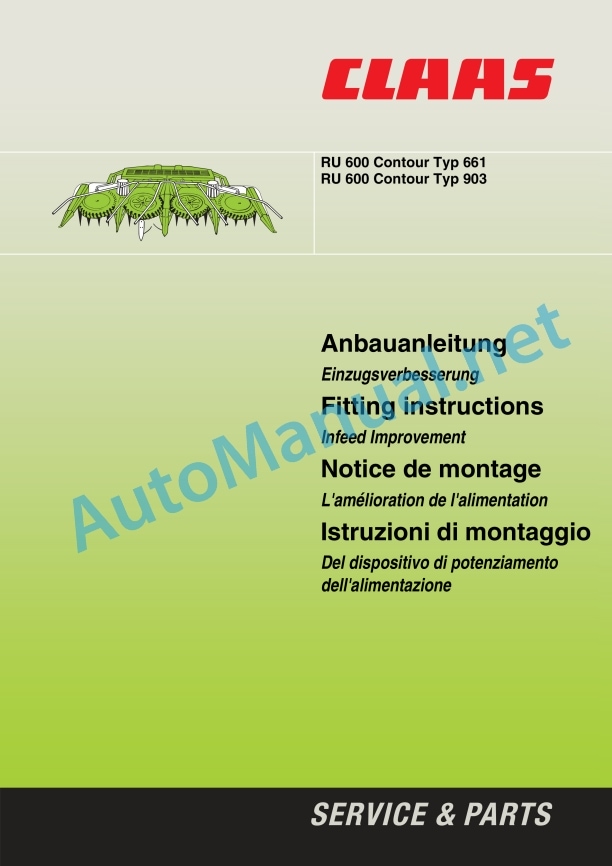
Claas Ru-600 Contour (903) Forage Harvesters Assembly Instruction EN
$50.00
- Model: Ru-600 Contour (903) Forage Harvesters
- Type Of Manual: Assembly Instruction
- Language: EN
- Format: PDF(s)
- Size: 26.8 MB
File List:
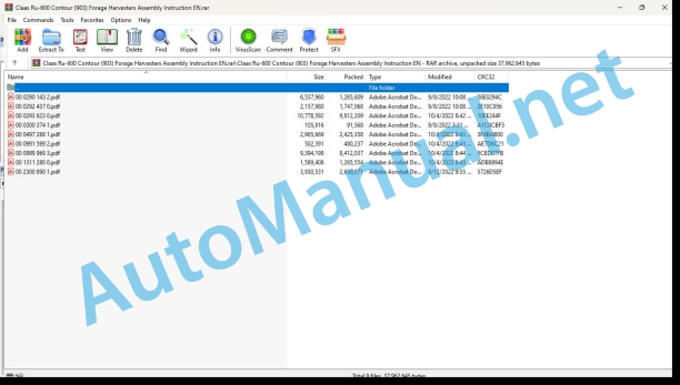
00 0290 143 2.pdf
00 0292 437 0.pdf
00 0293 623 0.pdf
00 0300 374 1.pdf
00 0497 268 1.pdf
00 0991 599 2.pdf
00 0999 969 3.pdf
00 1311 280 0.pdf
00 2300 890 1.pdf
00 0293 623 0.pdf:
1 Machine overview
2 Introduction
Introduction
Validity
3 Table of contents
4 Preface
Special care
Identification plate
Transport on public roads
Protective equipment for road transport
Driving lights during road transport
Ballasting
5 Safety rules
Identification of warning and danger signs
Intended use
General Safety and Accident Prevention Instructions
Safety decals with pictorials
Safety prop
6 Specifications
RU 600 Contour
RU 600 Auto-Contour
7 Prior to operation
Loading and unloading the maize header
Mounting the maize header for the first time
Adjustments to the forager
Additional weights
Required additional weights
Order numbers – additional weights
Additional lighting for road transport
Setting the drop rate
Mounting the safety covers
Assembly of maize header
Mount locking mechanism rod
Mount drive for intake auger (for delivery to USA)
Installing the universal drive shaft
Installing down-crop augers
Assembly of crop dividers/divider points
Installing crop dividers
Installing divider points
Adjusting crop dividers
Attaching push bar
Removing protective strip
Removing transport frame
Check and observe the following before putting into operation
Mounting the maize header
To mount the maize header, proceed as follows:
Unlocking
Attaching the maize header
Adjusting the lock mechanism
Adjusting the locking rods
Connecting the hydraulics
Connecting the power supply
Connecting universal drive shaft on forager
Adjusting dog clutch
Pivoting frame
Unlocking the swing stop
Locking the swing stop
Prop stands
Work and transport position
Transport position
Working position
Unhitching/setting down the maize header
8 Operation
Raising and lowering the maize header
Raise and lower side arms of the maize header
Using the maize header
Crop dividers
Adjusting the angle of the crop dividers
Adjusting the outer dividers
Adjusting the push bar
Adjusting the chopping length
Chopping length range
Adjusting the serrated strips
Adjusting the knives
Adjusting the hitch
Harvesting down-crop
OPTIONAL EQUIPMENT
Down-crop cones (D03 0070)
Deflector bar height increase (D03 0060)
CLAAS Autopilot (R03 0110)
Adjusting the sensors:
CLAAS Auto-Contour (R03 0070)
9 Maintenance
Important Maintenance Instructions
Spare parts
Hydraulic system
Lubrication
Gearboxes
Spur wheel gear (A)
Angle drive (B)
Main drive (C)
Bevel gear (D)
Angle drive (E)
Rotor drive (F)
Clearing gear (G)
Drives (H, I) for down-crop augers
Clutches
Lubricating the drive chain
Tensioning the drive chain
Replacing knives
Changing the knives:
Spring adjustment
Folding frame spring tension
Spring tension of intake auger
Hydraulic system
Hydraulic hose connections
Fixing elements
Bolted connections
Connecting elements
End of season storage
Lubricants chart
10 Lubrication chart
Safety rules
Lubricants
Lubrication
00 0497 268 1.pdf:
Anbauanleitung
Einzugsverbesserung
1 Instructions
Instructions
2 Inhalt
3 Allgemeine Hinweise
Besons on the beach
Kennzeichnung von Warn- und Gefahrenhinweisen
Bestimmungsgeme Verwendung
Sicherheitaveckleber mit Warnbildzeichen
Allgemeine Sicherheitshinweise
4 Lieferumfang
Anbausatz Einzugsverbesserung 0497 266.1
5 Einzugsverbesserung
Abdeckungen demontieren
Zugfeder einbauen
Bohrung setzen
RU 600 Typ 661 bis Machine number 661 0 1804
RU 600 Typ 661 ab Machine number 661 0 1805 and RU 600 Typ 903
Zugfedern mountain
Mitnehmer montieren
Leisten auf Einzugschnecke montieren
You can open the doors and the beaches!
Fitting instructions
Infeed Improvement
1 Introduction
Introduction
2 Table of contents
3 General instructions
Of special importance
Identification of warnings and dangers
Designated use
Safety decals with warning symbols
General safety instructions
4 Shipping package
Fitting kit infeed improvement 0497 266.1
5 Fitting the feed improvement
Dismantling covers
Removing the tension springs
Mounting the tension springs
Increasing the hole
RU 600 Type 661 up to machine number 661 0 1804
RU 600 Type 661 from machine number 661 0 1805 and RU 600 Type 903
Fitting the tension springs
Fitting the carriers
Fitting the rails to the infeed auger
Check and observe the following before putting into operation
Installation instructions
Improved diet
1 Introduction
Introduction
2 Table of contents
3 General tips
Important
Identification of warning and hazard requirements
Use as intended
Safety label with danger pictogram
General safety instructions
4 pieces supplied
Accessories for power improvement 0497 266.1
5 Mounting the power improvement
Dismantling the covers
Dismantle the tension springs
Install the tension springs
Perform the reaming
RU 600 model 661 up to no. machine 661 0 1804
RU 600 model 661 from no. machine 661 0 1805 and RU 600 model 903
Install the tension springs
Install the drive spindle
Mount the flats on the feed screw
Check the following points before putting the machine into operation!
Mountain structure
Power supply device
1 Introduction
Introduction
3 General information
Important warnings
Symbols concern warnings and warnings of pericolo
Norm per il corretto impiego
Decal with pericolo symbol
General safety information
4 Complessivo di fornitura
Power supply device mounting kit 0497 266.1
5 Button of the power supply device
Smontare the cover
Smontare the soft tenditrici
Montare the soft tenditrici
Prepare for it
RU 600 Tipo 661 fino alla machine Nr. 661 0 1804
RU 600 Tipo 661 from machine Nr. 661 0 1805 e RU 600 Tipo 903
Montare the soft tenditrici
Show and transmit
Montare le barre sulla coclea convogliatrice
Prima della messa en campo, controllare et osservare!
00 0999 969 3.pdf:
1 Instructions
Instructions
2 Inhalt
3 Allgemeine Hinweise
Besons on the beach
Kennzeichnung von Warn- und Gefahrenhinweisen
Bestimmungsgeme Verwendung
4 Lieferumfang
Lieferumfang / Anbausatz 999 959.2
5 Anbauarbeiten
Anbau vorbereiten
Verlegen des Kabelbaums
Anschluss Auto Conto links
Auto Contour rights
Autokontur – Einheit rechts / links anbauen
Zylinder einbauen
Anpassungen am Hcksler
Anpassung an Hydraulik
Anpassung am Bedienpult
Switching to a Zentralektrik
Verbindungen zum Hcksler
Einstellung Auto Contour
1 Introduction
Introduction
2 Table of Contents
3 General instructions
Of special importance
Identification of warnings and dangers
Designated use
4 Package list
Package list/Mounting kit 999 959.2
5 Mounting work
Prepare the installation
Routing the wiring loom
Connecting the Auto Contour system on the l.h. side
Connecting the Auto Contour system on the r.h. side
Installation of the Autocontour – Unit left hand / right hand unit
Installing the cylinders
Adapting the drilling harvester
Adapting the hydraulic system
Adapting the control box
Adapting the central terminal compartment
Connections to the drilling harvester
Adjusting the Auto Contour system
Maintenance
1 Introdtion
Introduction
3 General instructions
Important
Identification of warning and hazard requirements
Use in accordance with intended use
4 pieces supplied
Parts supplied / Installation kit 999 959.2
5 Installation work
Prepare the assembly
Installation of the electrical harness
Connecting the Auto Contour system on the left side
Connecting the Auto Contour system on the right side
Installation of Autocontour unit on the right/left side
Installation of the cylinders
Adaptation of the forage harvester
Adaptation of the hydraulic system
Adaptation of the control box
Adaptation of the central electrical system
Connections on the forage harvester
Adjusting the Auto Contour system
Interview
1 Introduction
Introduction
3 General instructions
To operate in private mode
Symbols concern warnings and warnings of pericolo
Norm per il corretto impiego
4 Complessivo di fornitura
Complessivo di fornitura / Set di montaggio 999 959.2
5 Mountain Lavori
Preparatory dishes
Installation of matassa cavity
Connecting the Auto Contour system to the next fault
Connecting the Auto Contour system to the side of the system
Montaggio del unit Autocontour sinistra / destro
Montaggio dei cilindri
Adattamento della trincia semovente
Adattamento dellimpianto idraulico
Adjustment of the command box
Electrical central adjustment
Collegamenti deseguire sur la trincia
Auto Contour system registration
Maintenance
1 Introduction
Introduction
2 Content
3 Generalities
Provide special attention
Identification of warning and warning signs
Use in accordance with specifications
4 Volumes of entrega
Storage volume / Adaptation kit 999 959.2
5 Mounting works
Preparations
Location of the trunk of cables
Connecting the Auto Contour system to the left side
Connecting the Auto Contour system to the last one
Montaje del unidad Autocontour derecho / izquierda
Cylinder assembly
Adaptation of the forrajechadora
Adaptatinstallation
Adaptation of the mando box
Adaptation of the electrical quadrant
Connections to be made in the forraje cosechadora
Adjusts the Auto Contour system
Maintenance
00 1311 280 0.pdf:
1 Einleitung
1.1 Allgemeine Hinweise
1.1.1 Handhabung der Anleitung
1.1.2 Gltigkeit der Anleitung
2 Sicherheit
2.1 Beachten
2.1.1 Besonders zu beachten
2.1.2 Kennzeichnung von Warn- und Gefahrenhinweisen
3 Lieferumfang
3.1 Kettenspanner RU 600
3.1.1 Teilesatz 001 311 277 0
4.1 Vorbereitung
4.1.1 Vorsatzgert vorbereiten
4.1.2 Maschine auer Betrieb setzen
4.1.3 Schweiarbeiten
4.1.4 Schutzvorrichtung ausbauen
4.2 Anbau Kettenspanner
4.2.1 Block einschweien
4.2.2 Kettenspanner anbauen
4.2.3 Kettenspanner einstellen
4.2.4 Schutzkufe anpassen
4.2.5 Schutzvorrichtungen anbauen
4.3 Vor Inbetriebnahme
4.3.1 Probelauf vorbereiten und durchfhren
1 Introduction
General Informationual
1.1.2 Validity of instructions
2 Safety precautions
2.1 Important
2.1.1 Important information
2.1.2 Identification of warning and danger signs
3 Package list
3.1 Chain tensioner RU 600
3.1.1 Parts kit 001 311 277 0
4 Mounting
4.1 Preparation
4.1.1 Preparing the front attachment
4.1.2 Putting the machine out of action
4.1.3 Welding Work
4.1.4 Detaching the protective guard
4.2 Fitting the chain tensioner
4.2.1 Welding in the block
4.2.2 Fitting the chain tensioner
4.2.3 Adjusting the chain tensioner
4.2.4 Adapting the protective skid
4.2.5 Attaching the safety guards
4.3 Before putting the machine into operation
4.3.1 Prepare and carry out a test run
1 Introduction
1.1 General advice
1.1.1 Use of the notice
1.1.2 Validity of the notice
2 Security advice
2.1 Observer
2.1.1 Important
2.1.2 Markage of warnings and dangers
3 Pices fournies
3.1 Chain tensioner RU 600
3.11 Jeu de pices 001 311 277 0
4 Montageeparation
4.1.1 Prepare frontal equipment
4.1.2 Eteindre la machine
4.1.3 Soudures
4.1.4 Remove the security devices
4.2 Pose of the chain tensioner
4.2.1 Souder le bloc
4.2.2 Place the chain tensioner
4.2.3 Adjust the chain tensioner
4.2.4 Adapter the protection coating
4.2.5 Install the security devices
4.3 Avant la mise en service
4.3.1 Prepare a function test and implement it
1. Introduction
1.1 General indications
1.1.1 Application of the user manual
1.1.2 Validity of the user manual
2 Safety
2.1 To be observed
2.1.1 Important warnings
2.1.2 Warning and danger signs
3 Total supply
3.1 RU 600 chain tensioner
3.1.1 Special series 001 311 277 0
4 Assembly
4.1 Preparation
4.1.1 Prepare the head
4.1.2 Put the machine out of operation
4.1.3 Welding work
4.1.4 Removing the protective device
4.2 Assembling the chain tensioner
4.2.1 Weld the block
4.2.2 Fit the chain ensioner
4.2.3 Adjusting the chain tensioner
4.2.4 Adaptation of the protection slide
4.2.5 Mounting the protection device
4.3 Before deployment
4.3.1 Preparation and execution of operational tests
1 Introduction
1.1 General indications
1.1.1 Using the instructions
1.1.2 Validity of the instructions
2 Safety Medications
2.1 Observe
2.1.1 Especially important
2.1.2 Reporting of warnings and warnings
3 Suminister Council
3.1 Cadena tensor RU 600
3.1.1 Juego de piezas 001 311 277 0
4 Assembly
4.1 Preparation
4.1.1 Prepare the cabezal
4.1.2 Place the machine out of service
4.1.3 Soldering work
4.1.4 Disassemble the protector device
4.2 Montaje del tensor de cadenas
4.2.1 Soldier the blockade
4.2.2 Mount the cadena tensor
4.2.3 Adjust the cadence tensor
4.2.4 Adapt the pad protector
4.2.5 Mount the protection devices
4.3 Antes de la puesta en marcha
4.3.1 Prepare and carry out an operational test
00 2300 890 1.pdf:
General information
safety instructions
Handling the instructions
Warning symbols
General instructions
Safety precautions
Handling of manual
Symbols and warnings
Remarques generales
Security Councils
Utilization of the notice
Symbols conseils d’avertissement
Avvertenze generali
Safety standards
Impiego del Manuale di istruzioni
Symbols with averted images of the perimeter
General indications
Medidas de seguridad
Usage of manual instructions
Symbols of warning indicators
John Deere Repair Technical Manual PDF
John Deere Repair Technical Manual PDF
John Deere PowerTech M 10.5 L and 12.5 L Diesel Engines COMPONENT TECHNICAL MANUAL CTM100 10MAY11
John Deere Repair Technical Manual PDF
John Deere Application List Component Technical Manual CTM106819 24AUG20
John Deere Repair Technical Manual PDF
John Deere Diesel Engines PowerTech 4.5L and 6.8L – Motor Base Technical Manual 07MAY08 Portuguese
John Deere Repair Technical Manual PDF
John Deere Transmission Control Unit Component Technical Manual CTM157 15JUL05
John Deere Repair Technical Manual PDF
John Deere Repair Technical Manual PDF
John Deere Diesel Engines POWERTECH 2.9 L Component Technical Manual CTM126 Spanish
New Holland Service Manual PDF
John Deere Parts Catalog PDF
John Deere Harvesters 8500 and 8700 Parts Catalog CPCQ24910 Spanish

