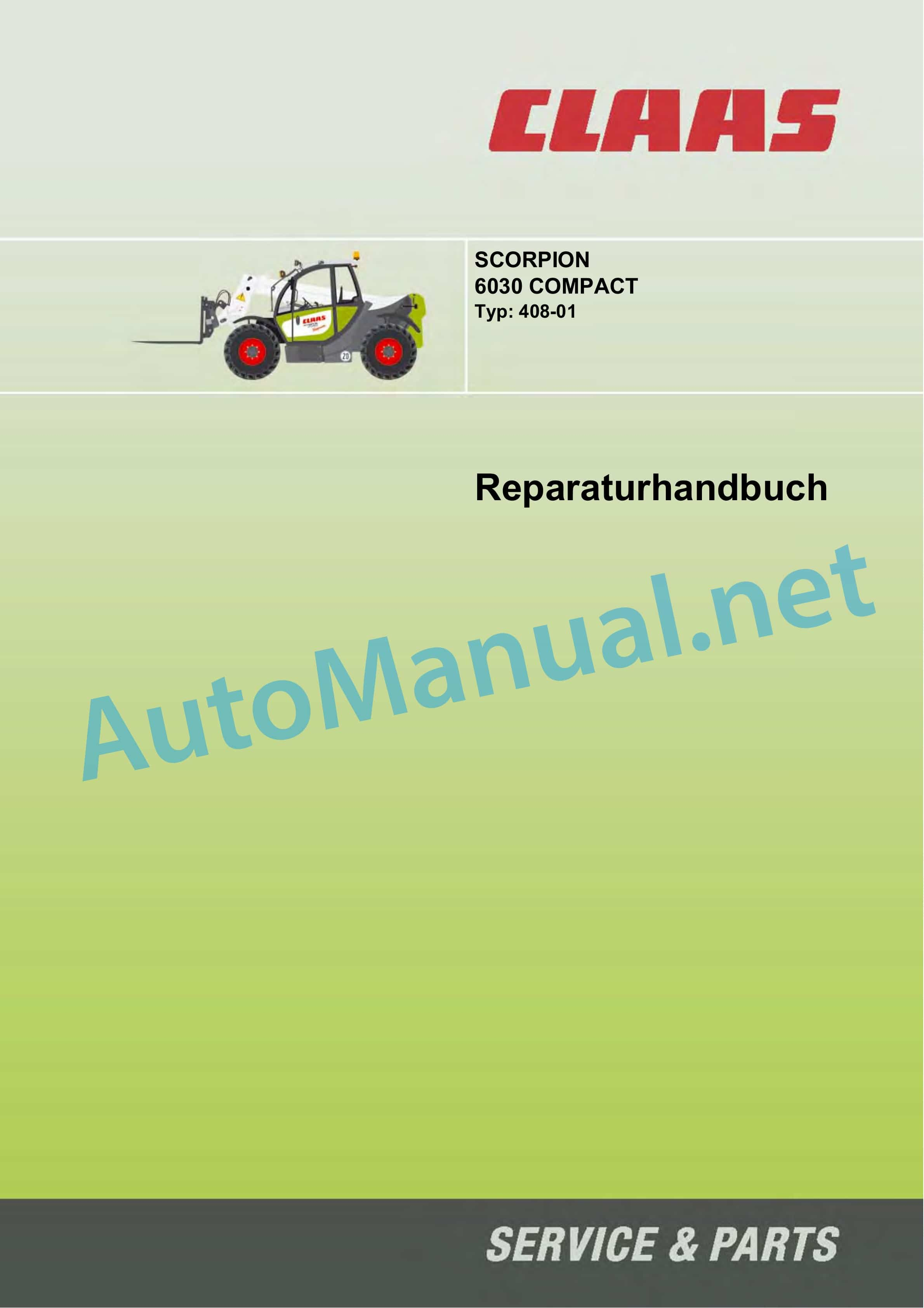
Claas SCORPION 6030 CP (K10) Telehandlers Repair Manual DE
$300.00
- Model: SCORPION 6030 CP (K10) Telehandlers
- Type Of Manual: Repair Manual
- Language: DE
- Format: PDF(s)
- Size: 104 MB
File List:
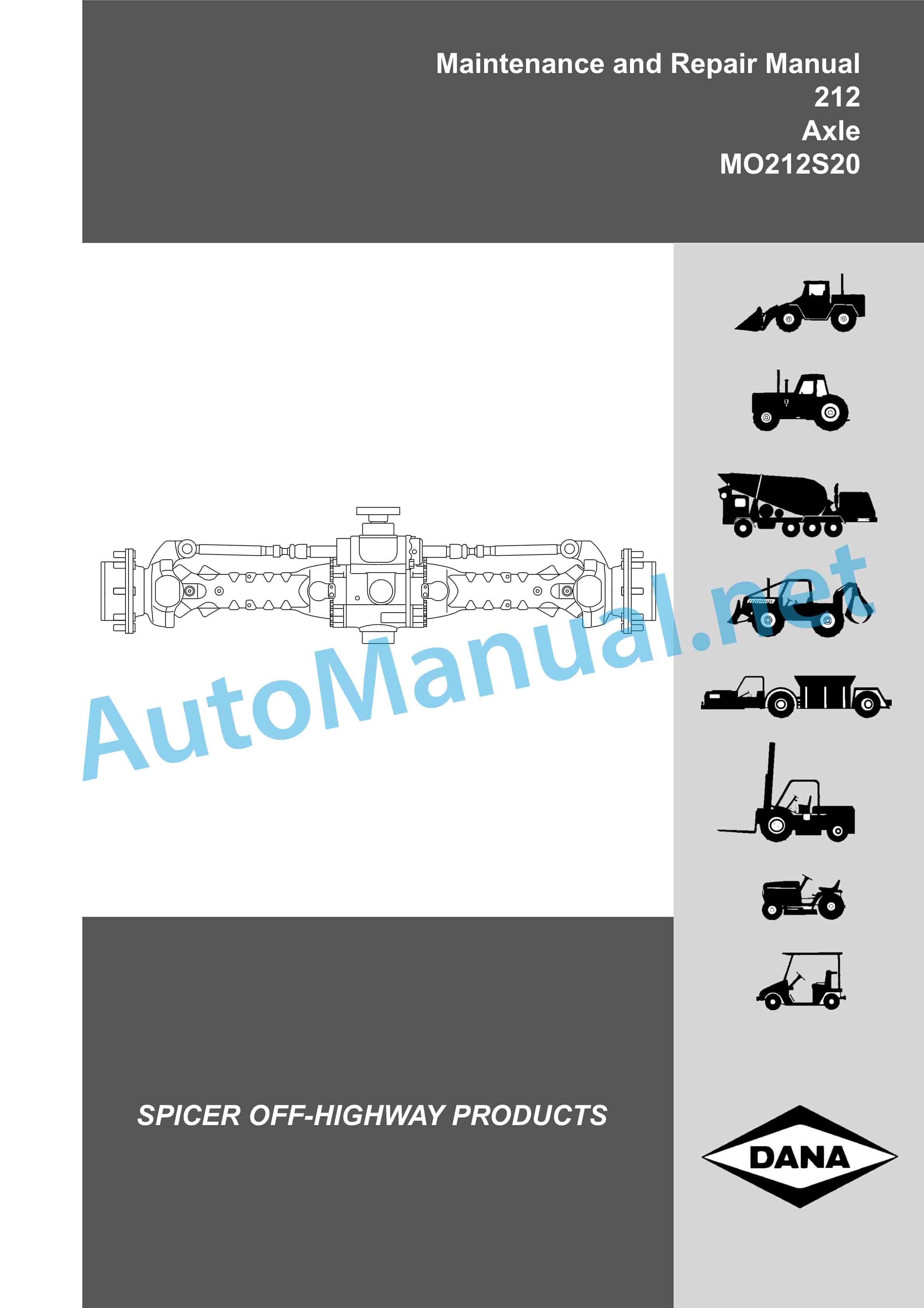
– 00 0291 634 3.pdf
– 00 0300 130 0.pdf
– 00 0300 133 0.pdf
– 212 Axle MO212S20.pdf
– DEUTZ D 2011 w, TD 2011 w, TCD 2011 w.pdf
– SCORPION Repairing the high-speed gearbox.pdf
00 0291 634 3.pdf
Table of Content:
1 SCORPION
2 6030 compact
2.1 Table of Contents
2.2 1 Overview: Vehicle, technical data
2.3 3 Maintenance and care work
2.4 4 Engine / Cooler / Diagnosis
2.5 5 travel drive
2.6 6 axes
2.7 7 Brake
2.8 8 Steering
2.9 9 Working hydraulics
2.10 10 Electrical systems
00 0300 130 0.pdf
Table of Content:
1 Assembly instructions replacing high-speed gearbox version II with high-speed gearbox version III
1.1 Qualification
1.2 Required tools
1.3 Preparatory work
1.4 Dismantling the high-speed gearbox
1.5 Overview
1.6 Pre-assembly of overdrive transmission (new)
1.7 Assembly of the high-speed gearbox
1.8 Commissioning
2 Assembly instructions for replacement of version II by version III high-speed gearbox
2.1 Qualification
2.2 Necessary tools
2.3 Preparatory work
2.4 Removing the high-speed gearbox
2.5 Overview
2.6 Pre-assembling the high-speed gearbox (new)
2.7 Installing the high-speed gearbox
2.8 Putting into operation
3 Instructions for assembling for the replacement of a version II with a version III of the box surmultiplie
3.1 Qualification
3.2 Necessary tools
3.3 Travaux prparatoires
3.4 Dpose de la bote surmultiplie
3.5 Vue densemble
3.6 Pr-assemblage de la bote surmultipli 2.5 Assembly: parking brake switch
2.6 Putting into operation
3 Instructions for assembling the station interrupter
3.1 Description
3.2 Qualification
3.3 Necessary tools
3.4 Travaux prparatoires
3.5 Installation of the interrupter of the station block
3.6 Mise en marche
DEUTZ D 2011 w, TD 2011 w, TCD 2011 w.pdf
Table of Content:
1 workshop manual
2 Table of Contents
2.1 1 Preface
2.2 2 General
2.3 3 User instructions
2.4 4 Technical data
2.5 5 Work card overview
2.6 6 work cards
3 Check compression pressure
4 Mounting and dismounting the motor on the assembly stand
5 Adjust valve clearance
6 Removing and installing rocker arms and rocker arm bracket
7 Disassemble and complete the rocker arm and rocker arm bracket, check
8 Removing and installing cylinder head
9 Measure piston protrusion
Removing and installing 10 valves
11 Check valves
12 Check valve guide
13 Check valve residft
16 Replace crankshaft seal (flywheel side)
17 Replace crankshaft seal (opposite flywheel side)
18 Check connecting rod
19 Removing and installing piston pin bushing
20 Removing and installing crankshaft
21 Removing and installing piston and connecting rod
22 Check piston
23 Check piston rings and piston ring grooves
Removing and installing 24 piston cooling nozzles
25 Removing and installing crankcase ventilation
Check 26 cylinders
27 Removing and installing the front cover
28 Dismantle and complete the front cover
29 Removing and installing the rear cover
30 Removing and installing connection housing
31 Removing and installing camshaft bearings, checking
32 Replace camshaft seal (opposite flywheel side)
33 Renew timing belt and tension pulley
34 Removing and installing timing belt wheel
35 Removing and installing camshaft
36 Check camshaft
37 Removing and installing control rod
38 Removing and installing guide bushings (control rod)
39 Removing and installing speed sensor
40 Removing and installing exhaust pipe
41 Removing and installing charge air line
42 Removing and installing exhaust gas turbocharger
43 Removing and installing air intake pipe
44 Removing and installing exhaust gas recirculation valve
45 Removing and installing exhaust gas recirculation line
46 Removing and installing the exhaust gas manifold (exhaust gas recirculation)
47 Removing and installing sensor (exhaust gas recirculation)
48 Removing and installing magnetic clip (exhaust gas recirculation)
49 Removing and installing lifting magnet (start quantity release)
Renew 50 injection lines
51 Removing and installing injection pump
52 Check start of funding
53 Determine the thickness of the shim
54 Removing and installing fuel injectors
55 Check fuel injectors
56 Removing and installing lifting magnet (boost pressure-dependent full load stop)
57 Removing and installing the boost pressure-dependent full load stop
58 Removing and installing fuel lines
59 Removing and installing fuel filter console
60 Removing and installing fuel pump
61 Removing and installing lubricating oil pump
62 Removing and installing oil suction pipe
63 Removing and installing the lubricating oil pan (sheet metal lubricating oil pan)
64 Removing and installing the lubricating oil cooler
65 Removing and installing oil pressure control valve
66 Removing and installing oil filter console
67 Removing and installing oil pressure switch
68 Removing and installing thermostat (lubricating oil cooler)
69 Removing and installing control cable
70 Removing and installing coolant pump
71 Check thermostat (when removed)
72 Removing and installing thermostat
73 Removing and installing the thermostat housing
74 Removing and installing temperature sensor
75 Removing and installing lifting magnet (engine shutdown)
76 Removing and installing the V-belt pulley
77 Replace V-belt, check V-belt tension
78 Removing and installing flywheel
79 Renew starter gear on flywheel
80 Removing and installing hydraulic pump
81 Renew timing belt and tension pulley (hydraulic pump)
82 Removing and installing generator
83 Removing and installing starter
Removing and installing 84 glow plugs
85 Removing and installing glow plug
86 7 Commercially available tools
87 8 Special tools
SCORPION Repairing the high-speed gearbox.pdf
Table of Content:
1 Assembly instructions repairing the high-speed gearbox
1.1 Qualification
1.2 Preparatory work
1.3 Dismantling the overdrive gearbox
1.4 Dismantling the gearbox cover
1.5 Dismantle the control cover from the gearbox housing
1.6 Remove engine
1.7 Dismantle the control cover
1.8 Mounting the control cover
1.9 Assemble the gearbox housing
1.10 Mount output shaft
1.11 Mounting the engine
1.12 Install the engine in the swivel bracket
2 Assembly instructions repairing the high-speed gearborom the gearbox housing
2.6 Removing the gear unit
2.7 Removing the control cover
2.8 Installing the control cover
2.9 Installing the gearbox housing
2.10 Installing the output shaft
2.11 Installing the gear unit
2.12 Installing the gear unit in the swivel yoke
3 Instructions dassemblage repair the box surmultiplie
3.1 Qualification
3.2 Travaux prparatoires
3.3 Dposer la bote surmultipli?
John Deere Repair Technical Manual PDF
John Deere Parts Catalog PDF
John Deere Harvesters 8500 and 8700 Parts Catalog CPCQ24910 Spanish
John Deere Repair Technical Manual PDF
John Deere PowerTech M 10.5 L and 12.5 L Diesel Engines COMPONENT TECHNICAL MANUAL CTM100 10MAY11
John Deere Repair Technical Manual PDF
John Deere Repair Technical Manual PDF
John Deere Transmission Control Unit Component Technical Manual CTM157 15JUL05
John Deere Repair Technical Manual PDF
John Deere Repair Technical Manual PDF
John Deere Repair Technical Manual PDF
John Deere Parts Catalog PDF
John Deere Tractors 7500 Parts Catalog CPCQ26568 30 Jan 02 Portuguese
John Deere Repair Technical Manual PDF
John Deere Application List Component Technical Manual CTM106819 24AUG20

