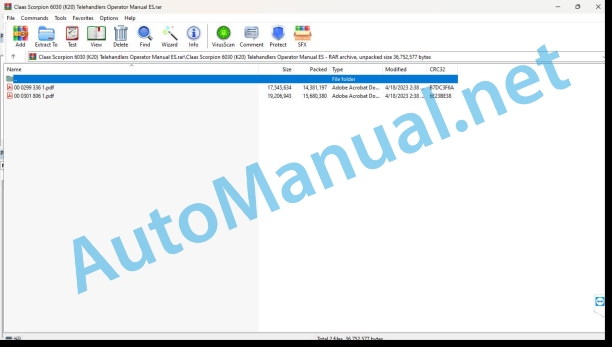
Claas Scorpion 6030 (K20) Telehandlers Operator Manual ES
$40.00
- Model: Scorpion 6030 (K20) Telehandlers
- Type Of Manual: Operator Manual
- Language: ES
- Format: PDF(s)
- Size: 28.7 MB
File List:
00 0299 336 1.pdf
00 0301 806 1.pdf
00 0299 336 1.pdf:
General index
CE declaration of conformity
CE declaration of conformity
CE declaration of conformity
CE declaration of conformity
1 Preface
1.1 Instruction manual
Important notices regarding service personnel
Important notices regarding the instruction manual
Explanation of symbols and abbreviations
1.2 Warranty and liability
Notice on maintenance, repairs and spare parts
2 Security
2.1 Safety symbols and signal words
Explanation
2.2 Rules of conduct and safety instructions
Preconditions for operation
2.3 Qualification of operating and maintenance personnel
Owner Duties
Required operator knowledge
Operator preparation measures
2.4 Operation
Preparation measures
Work environment
Area of risk
Transportation of people
Perfect mechanical condition
Starghe machine
Machine operation
Driving on public roads/places
Stop the machine engine
Stop and secure the machine
2.5 Use of lifting equipment
Conditions
Secure, guide and remove loads
Use of lifting equipment
2.6 Trailer service
Towing service
2.7 Use of implements
Implements
Functioning
Assemble implements
2.8 Towing, loading and transporting
Crane loading
Transport
2.9 Maintenance
Maintenance
Personal safety measures
Preparation measures
Measures for implementation
Modifications and spare parts
Protective structures
2.10 Measures for risk prevention
Caterpillars
Hydraulic and compressed air system
Electric system
Safety instructions for internal combustion engines
Refuel and bleed the fuel system
Handling oils, fats and other substances
Risk of fire
Work near electrical power conduits
Work near non-electrical power conduits
Behavior during a storm
3 Introduction
3.1 Global view of the machine
Model name and commercial name (synopsis)
3.2 Synoptic description of the machine
Main components of the machine
Hydrostatic propulsion
Working hydraulics and steering on all 4 wheels
Refrigeration system
3.3 Notices and regulations regarding working with the machine
General information about the machine
Safe use of the machine
Expected use
Abusive use
Permissible temperature range for normal operation
Driving license
Machine inspections
Documents on board the machine
Onboard equipment
Machine warning signs on public roads (option)
Areas of application and use of implements
3.4 Signage
Synopsis of the signs on the left of the machine
Synopsis of the signs on the right of the machine
Overview of the signage on the front of the machine
Overview of the signage on the rear of the machine
Name plates
Warning signs
Information signs
4 Start-up
4.1 Cabin/control position
Important Cab Notices
Safety instructions on entering and exiting the cabin
Lock/unlock the door
Open/close the rear window
Emergency exit through the rear window
Emergency exit – glass breaking hammer (option)
Safety instruction – right side window
Field of vision when driving on public roads
Field of vision during work
Mirror adjustment
Camera (option)
Rear defogger (option), mirror heating (option)
Seat adjustment
Air suspension seat (option)
Seat belt (lap belt)
Main battery switch
Fire extinguisher (option)
Electronic immobilizer with key system (option)
Preheating of hydraulic oil and coolant (option)
Fuel preheating (option)
Holes and tanks (option)
4.2 Control elements: overview
Description of the control elements
Cabin interior
Instrument panel with control elements
4.3 Overview of control lamps and pilot lights
Control lamps and warning lights on the indicator instrument
Control lamps – right instrument panel
Control lamps – steering mode switch
Control lamps and warning lights – lower on the instrument panel
Checking control lamps and warning lights
Indication on the indicator instrument
Acoustic warning messages
Indicators
4.4 Preparations
Important notices before starting up the machine
Requirements and notices for service personnel
Break-in time
Checklists
Instructions about driving on public roads
Preparations for driving on public roads
Lock the joystick
Brake, steering and lighting operation control
4.5 Starting and stopping the engine
Preparations for starting the engine
To start the engine
Starting the engine with starting aid
Avoid loading the engine in low load operation
stop the engine
5 Management
5.1 Address
Steering column height and tilt adjustment
Check address
Synchronize address
Synchronize the address in manual mode
Front axle steering
4 wheel steering
Diagonal direction (crab step)
5.2 Throttle control
Accelerator pedal
Manual throttle (option)
5.3 Brake
Brake pedal/inching (service brake)
Parking break
5.4 Driving
Drive the machine
Overview of driving speeds
Change driving speed
Select the direction of travel
Reversible gear (change of direction of travel)
Neutral, stop the machine
Stop/park the machine
Inching device (option)
5.5 Differential lock
Important notices about differential lock
5.6 Lighting/signaling system
Position light/low beam
High beam/warning light
Work lights (standard/option)
Interior lighting
Flashing
Emergency flashers
Omnidirectional identification light (option)
Backup warning (option)
5.7 Windshield wiper/washer system
Windshield washer/rear window washer system control
Windshield washer system reservoir
5.8 Heating, ventilation and air conditioning
Heating and ventilation
Air conditioning (option)
5.9 Working hydraulics
Overload control
Telescopic arm control
“Smart Handling” overload control
Overview of hydraulic control circuits
Regulation of the amount of hydraulic oil (option)
3rd control circuit
Switch the 3rd control circuit to plug couplings B with the switching valve (option)
Continuous operation of the 3rd control circuit (option)
Pressure relief on quick hitch quick couplings
5.10 Implements
Check the implement locking holes
Mounting an Implement to the Quick Hitch with Hydraulic Interlock
Mounting an Implement to the Quick Hitch with Mechanical Interlock
Depositing anlement frhe quick hitch with mechanical interlock
Depositing an implement from the quick hitch with hydraulic interlock
Serial spoon
Multipurpose spoon (option)
Pallet forks
Assemble implements from other manufacturers (option) for model 415-01_6030
Assemble implements from other manufacturers (option) for model 415-01_6035
Assemble implements from other manufacturers (option) for model 415-03
Assemble implements from other manufacturers (option) for model 415-05
5.11 Working with the machine
“Break valve” safety device
Driving on public roads with a bucket
Safety instructions for working with buckets
Transport tour with full bucket
Load stabilizer for loader arm (option)
Work with standard spoon
Working with the multipurpose spoon
Working with pallet forks
Work with a crane arm (option)
Bucket repositioning (option, in preparation)
Tilting cylinder interlock (option)
Front powerlet (option)
5.12 Emergency descent
Emergency lowering of the loader arm in case of diesel engine failure
5.13 Options
Automatic trailer coupling (option)
Ball trailer coupling ø 80 mm (option)
Autohitch coupling (option)
Tipper handling – trailer (option)
Trailer compressed air brake system (option)
Hydraulic trailer brake (option)
Reversible fan (option)
PROFI CAM / PROFI CAM PLUS (option)
Before commissioning the PROFI CAM/PROFI CAM PLUS
Using the PROFI CAM/PROFI CAM PLUS
5.14 Shutting down and restarting
Longer machine shutdown
Preserve the diesel engine
5.15 Final put out of service
Disposal Notice
Prepare for machine disposal
Elimination
6 Transportation
6.1 Towing the machine
Trailer Notices
Deactivate the hydraulic pump
Rear towing device
Front towing device
Tow the machine
After towing
6.2 Load the machine
Load the machine onto a transpor vehicle
Crne loading
6.3 Transport the machine
Safety instructions on transportation
Tie down the machine
7 Maintenance
7.1 Maintenance notice
Responsibilities and conditions
Important safety instructions for maintenance work
Telescopic arm safety shoring
7.2 Overview of maintenance work
Maintenance program
maintenance sticker
Explanation of the symbols on the maintenance sticker
7.3 Fuels and lubricants
Synopsis of lubricants
Diesel specification
Refrigerant
Important notice regarding operation with biodegradable oils
7.4 Maintenance points
Engine hood interlock
engine tank
Maintenance access to the back of the machine
Access to machine fuses
7.5 Cleaning and conservation work
Important notices regarding cleaning and maintenance work
Cleaning the interior of the cabin
Cleaning the exterior of the machine
Cleaning the engine and engine compartment
Check screw connections
Check rotation points and hinges
7.6 Greasing work
Preparation work for greasing
Grease the rear axle swing bearings
Grease the planetary bearings (front and rear axles)
Grease the door
Grease the telescopic arm
Checking the sliding plates
Apply spray oil to the friction surfaces after working in a saline environment (with a spray lance)
Central lubrication system (option)
Grease with central lubrication system (option)
Fill the central lubrication system (option)
7.7 Fuel system
Important safety instructions on refueling
Service stations
Check/clean fuel prefilter
Bleed the fuel system
Replace the fuel filter
7.8 Engine lubrication system
Important safety instructions regarding the engine lubrication system
Check the engine oil level
Add engine oil
Change the engine oil
Replace the engine oil filter
7.9 Cooling system
Safety instructions on the cooling system
Notices on control and cleaning work on the cooling system
Check coolant level
Add coolant
Bleed/replace coolant
Clean the radiator
Clean the radiator with the reversible fan (option)
7.10 Air filter
Important notice about cleaning the air filter
Clean the dust discharge valve
Change the filter cartridge
7.11 V-belt/toothed belt
Check/retension belt
7.12 Hydraulic system
Important notices regarding the hydraulic system
Hydraulic oil filter monitoring
Hydraulic oil level monitoring (option)
Check the hydraulic oil level
Add hydraulic oil
Check the tightness of the hydraulic system
Check the condition and age of the hydraulic hoses
7.13 Electrical system
Qualification of maintenance personnel
Battery Safety Instructions
Check/replace battery
Periodic control and maintenance work on the electrical system
Check the alternator
Check/replace relays, fuses on printed circuit board
Main fuse box with switching relays
7.14 Heating, ventilation and air conditioning
Important notice regarding cabin ventilation
Clean/replace cabin ventilation filter
Air conditioning system (option)
Important safety instructions for air conditioning
Fill the air conditioning system
Visual control of the air conditioning system
Clean the heat exchanger (condenser)
7.15 Windshield washer/rear window washer system
Windshield washer/rear window washer system reservoir
7.16 Axles/propulsion
Maintenance work on axles and propulsion
7.17 Brake system
Important safety instructions on the brake system
Check/add brake fluid
Compressed air brake system (option)
7.18 Tires
Important tire notices
Tire check
Remove the wheels
Mount the wheels
7.19 Conservation and maintenance of implements
7.20 Options maintenance
Automatic trailer coupling (option)
Ball trailer coupling ø 80 mm (option)
Autohitch trailer coupling (option)
Maintenance of the PROFI CAM/PROFI CAM PLUS
7.21 Exhaust gas purification
7.22 Machine conservation
Important notice regarding anti-corrosion protection (option)
Ensure long-lasting anti-corrosion protection
Cleaning
Application of the anticorrosive layer
Treatment of rusty surfaces
8 Malfunctions
8.1 Diesel engine malfunctions
8.2 Propulsion faults
8.3 Hydraulic system malfunctions
8.4 Electrical system breakdowns
Digital display of error codes
Overview of frame electronics error codes
Synopsis of diesel engine electronics error codes
Overview of cockpit electronics error codes
Overview of drive electronics error codes
Overview of joystick error codes
Overload Control Error Code Overview
Overview of steering electronics error codes
Overview of error codes for additional frame electronics
Error odes on the overlod control indicator
8.5 Malfunctions in the air conditioning system (option)
9 Technical data
9.1 Model and commercial name
9.2 Engine
Emission level 3b engine (valid for all EU member countries)
Emission level 3a engine (valid for non-EU countries)
Oil/water radiator fan
9.3 Propulsion/axles
variable pump
variable motor
front axle
Rear axle
9.4 Brakes
Service brake
Parking break
9.5 Tires
Tires for models 415-01_6030/415-01_6035
Tires for model 415-03/415-05
9.6 Address
9.7 Working hydraulics
Hydraulic pump
Protection of hydraulic cylinders
Speed: lift, tilt and push cylinders
Electrohydraulic pre-control
Usable consumer pressure in the additional control circuit (option)
9.8 Electrical system
Fuse equipment
Main fuse box with relays
Switching relay equipment
electrical groups
POFI CAM / PROFI CAM PLUS (option)
9.9 Tightening torques
General tightening torques
Specific tightening torques
9.10 Coolant
9.11 Acoustic emissions
9.12 Vibrations
9.13 Weight
9.14 Payload/carrying capacity/stability
Towed load/drawbar load
Breaking force
Bucket payload
Load diagrams
9.15 Dimensions
Dimensions with spoon (part I)
Dimensions with spoon (part II)
Dimensions with pallet forks
Alphabetical index
00 0301 806 1.pdf:
User manual
General index
CE declaration of conformity
Manufacturer’s declaration
1 Preface
1.1 User manual
1.2 Warranty and liability
2 Security
2.1 Safety symbols and signal words
2.2 Rules of conduct and safety instructions
2.3 Qualification of operating and maintenance personnel
2.4 Operation
2.5 Use of lifting equipment
2.6 Trailer operation
2.7 Use of implements
2.8 Towing, loading and transporting
2.9 Maintenance
2.10 Measures for risk prevention
3 Introduction
3.1 Global view of the machine
3.2 Summary description of the machine
3.3 Notices and regulations regarding working with the machine
3.4 Labeling
4 Start-up
4.1 Cabin/control position
4.2 Control elements: overview
4.3 Overview of control lamps and pilot lights
4.4 Preparations
4.5 Starting and stopping the engine
5 Management
5.1 Address
5.2 Throttle control
5.3 Brake
5.4 Propulsion
5.5 Differential lock
5.6 Lighting/signaling system
5.7 Windshield wiper/washer system
5.8 Heating, ventilation and air conditioning
5.9 Working hydraulic system
5.10 Implements
5.11 Working with the machine
5.12 Emergency descent
5.13 Options
5.14 Stop and restart
5.15 Final put out of service
6 Transportation
6.1 Towing the machine
6.2 Load the machine
6.3 Transport the machine
7 Maintenance
7.1 Maintenance notice
7.2 Overview of maintenance work
7.3 Fuels and lubricants
7.4 Maintenance points
7.5 Cleaning and conservation work
7.6 Greasing work
7.7 Fuel system
7.8 Engine lubrication system
7.9 Cooling system
7.10 Air filter
7.11 V-belt/toothed belt
7.12 Hydraulic system
7.13 Electrical system
7.14 Heating, ventilation and air conditioning
7.15 Windshield washer/rear window washer system
7.16 Axles/propulsion
7.17 Brake system
7.18 Tires
7.19 Conservation and maintenance of implements
7.20 Options maintenance
7.21 Exhaust gas purification
7.22 Machine conservation
8 Malfunctions
8.1 Diesel engine breakdowns
8.2 Faults in the travel mechanism
8.3 Hydraulic system malfunctions
8.4 Electrical system breakdowns
8.5 Malfunctions in the air conditioning system (option)
9 Technical data
9.1 Model and commercial name
9.2 Engine
9.3 Propulsion/axles
9.4 Brakes
9.5 Tires
9.6 Address
9.7 Working hydraulic system
9.8 Electrical system
9.9 Tightening torques
9.10 Coolant
9.11 Acoustic emissions
9.12 Vibrations
9.13 Weight
9.14 Payload/carrying capacity/stability
9.15 Dimensions
Alphabetical index
John Deere Repair Technical Manual PDF
John Deere Repair Technical Manual PDF
John Deere Application List Component Technical Manual CTM106819 24AUG20
John Deere Repair Technical Manual PDF
John Deere Repair Technical Manual PDF
John Deere Repair Technical Manual PDF
John Deere Transmission Control Unit Component Technical Manual CTM157 15JUL05
John Deere Parts Catalog PDF
John Deere Tractors 6300, 6500, and 6600 Parts Catalog CQ26564 (29SET05) Portuguese
John Deere Repair Technical Manual PDF
John Deere Repair Technical Manual PDF
John Deere Repair Technical Manual PDF


