Claas Scorpion 6035 (K21) Telehandlers Technical System EN
$300.00
- Model: Scorpion 6035 (K21) Telehandlers
- Type Of Manual: Technical System
- Language: EN
- Format: PDF(s)
- Size: 203 MB
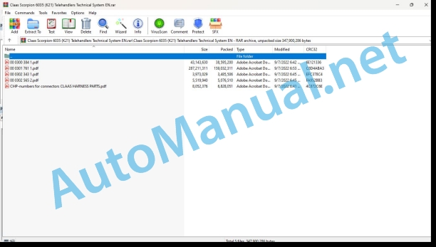
File List:
00 0300 384 1.pdf
00 0301 761 1.pdf
00 0302 343 1.pdf
00 0302 565 2.pdf
CHP-numbers for connectors CLAAS HARNESS PARTS.pdf
00 0300 384 1.pdf:
DEUTZ TD / TCD 3.6 L4 diesel engine
Table of contents
Introduction
Validity of manual
Validity of manual
General information
Technical Systems documentation and other sources of information
Importance of Technical Systems documentation
Personnel qualification and organization
Requirements made on all persons working with the machine
Alterations on the machine
Structural alterations
Additional equipment and spare parts
Requirements made on spare parts
Workplaces and persons travelling on the machine
Control of machine while running
Instructors travelling along during fieldwork
Technically flawless condition
Technically flawless condition of machine
Danger from damage to the machine
Respecting technical limit values
Hazard areas of the machine
Hazard areas
Hitching of machine to implement or trailer
Standing between machine and trailer
Hazard from engaged drive
Danger from machine parts that continue rotating
Safety devices
Keeping safety devices functional
Personal protective equipment
Personal protective equipment
Wearing suitable clothing
Safety markings
Keeping safety decals legible
Road safety
Hazards when driving on the road and on the field
Stability hazard
Preparing the machine for road travel
Parking the machine safely
Unsupervised parking
Keeping the machine free of foreign objects
Operating utilities
Unsuitable operating utilities
Safe handling of operating and auxiliary utilities
Fuel is detrimental to your health
Refrigerant is detrimental to your health
Environmental protection and disposal
Chemicals
Keeping the cab free of chemicals
Hazards from the work environment
Fire hazard
Potentially fatal electric shock from overhead lines
Behaviour in case of voltage flash-over due to overhead lines and when lightning strikes
Sources of hazards on the machine
Electric shock from electric system
Noise may damage your health
Vibrations may damage your health
Liquids under pressure
Compressed air
Toxic exhaust gases
Hot surfaces
Hazards when accessing and getting off the machine
Safe access and getting off
Hazards when working on the machine
Work only on the machine after shutting it down
Inspection, adjusting, maintenance and repair work
Raised machine parts and loads
Danger from welding work
Danger from painting work
Work on the electric system
Work on the diesel engine
Handling fuels
Handling hot liquids
Safety routines
First-aid measures
List of abbreviations
01 Engine
0102 Complete component
Complete component
TDC 3.6 L4 (DOC) engine, right service side
TDC 3.6 L4 (DOC) engine, left service side
TDC 3.6 L4 (CRT) engine, right service side
TDC 3.6 L4 (CRT) engine, left service side
Engine number and serial number of crank case
DEUTZ diesel engine identification plate
0110 Engine housing
Engine housing
Crankcase venting
Valve cover with oil separator
0115 Engine unit
Cylinder arrangement
0120 Cylinder head / Valves / Idler gear
Gear drive
Gear drive
Gearwheel housing
Valve train
Oil supply of hydraulic tappets and rocker arms
V-belt pulley / sensor wheel
V-belt pulley expansion pins / sensor wheel
Fixing the V-belt pulley to the crankshaft
0125 Injection / Fuel system
Injection / fuel system
Fuel system diagram
Injection system
Function of injectors
Description of injector function
Replacing the injectors
Description of function
IMA code
Parametrizing the IMA code with the CDS
Reset injector correction values with the CDS (1 of 2)
Reset injector correction values with the CDS (2 of 2)
Bosch CP4.1 high-pressure pump
Control block (FCU)
High-pressure pump service
Rail pressure relief valve
Reading out the number of openings of the rail pressure relief valve and resetting the counter with the CDS (1 of 2)
Reading out the number of openings of the rail pressure relief valve and resetting the counter with the CDS (2 of 2)
0130 Lubricating oil system
Lubricating oil system
Lubricating oil circuit
Lubricating oil system
Lubrication pump
Pressure relief valve
Oil pressure control valve
0135 Cooling system
Cooling system
Coolant diagram
Thermostat
Coolant pump union
Coolant pump
Coolant drain
0140 Exhaust system
Exhaust system
Turbocharging
Exhaust gas recirculation (EGR) system overview
Exhaust gas recirculation cooler (EGR cooler)
Exhaust gas recirculation (EGR) control valve
Exhaust gas recirculation (EGR) reed valve
Charge air sensor, TDC 3.6 L4 engine (DOC)
0155 Engine control
Engine monitoring and control
Note: regarding Technical Systems documentation
0165 Exhaust gas aftertreatment
Diesel oxidation catalytic converter (DOC)
Exhaust gas treatment with diesel oxidation catalytic converter (DOC)
Design of diesel oxidation catalytic converter (DOC)
Exhaust system
Turbocharging
Exhaust gas recirculation (EGR) system overview
Exhaust gas recirculation cooler (EGR cooler)
Exhaust gas recirculation (EGR) control valve
Exhaust gas recirculation (EGR) reed valve
Charge air sensor, TDC 3.6 L4 engine (DOC)
10 Electrical / Electronic equipment
1012 Modules / sensors
N005-KRA – Diesel engine electronics part 1/7
Key to diagram
Key to diagram
N005-KRA – Diesel engine electronics part 2/7
Key to diagram
Key to diagram
N005-KRA – Diesel engine electronics part 3/7
Key to diagram
Key to diagram
N005-KRA – Diesel engine electronics part 4/7
Key to diagram
Key to diagram
N005-KRA – Diesel engine electronics part 5/7
Key to diagram
Key to diagram
N005-KRA – Diesel engine electronics part 6/7
Key to diagram
Key to diagram
N005-KRA – Diesel engine electronics part 7/7
Key to diagram
Key to diagram
DEUTZ TCD 3.6 L4 DOC sensors
DEUTZ TCD 3.6 L4 DOC engine electronics and sensors
1085 Networks
Engine – machine BUS system (CAN)
Note: regarding Technical Systems documentation
1080 Electrical circuit diagram
Electric system power cabling circuit diagrams
SHEET 1 power cabling
Key to diagram
SHEET 2 power cabling
Key to diagram
Electric system unit cabling circuit diagrams
SHEET 1 unit cabling
Key to diagram
Engine wiring loom electric system circuit diagrams
SHEET 2 engine wiring loom
Key to diagram
SHEET 3 engine wiring loom
Key to diagram
SHEET 4 engine wiring loom
Key to diagram
SHEET 5 engine wiring loom
Key to diagram
Exhaust gas post-treatment electric system circuit diagrams
SHEET 1 exhaust gas post-treatment
92 Diagnosis
9220 Error codes engine (J1939)
FMI failure code (Failure Mode Indicator)
FMI 00 (Signal too high)
FMI 01 (Signal too low)
FMI 02 (Erratic signal)
FMI 03 (Voltage too high)
FMI 04 (Voltage too low)
FMI 05 (Current too low)
FMI 06 (Current too high)
FMI 07 (Mechanical failure)
FMI 08 (Abnormal frequency signal)
FMI 09 (Communication error)
FMI 10 (Rate of signal change too fast)
FMI 11 (multiple faults)
FMI 12 (ECU defective)
FMI 13 (Signal outside of calibration range)
FMI 16 (Parameter not available)
FMI 17 (ECU not responding)
FMI 18 (Power supply failure)
FMI 19 (Software conditions not met)
FMI 95 (no signal change)
FMI 96 (CAN Bus system defective)
FMI 97 (Erratic condition)
FMI 98 (Warning)
FMI 99 (Info)
DEUTZ (DTC) diesel engine and ISO J1939 (SPN) fault code list
Description of function
00 0301 761 1.pdf:
SCORPION6030 (K20 / 415-11)6035 (K21 / 415-11)7030 (K22 / 415-13)7035 (K23 / 415-15)
Table of contents
Introduction
Validity of Technical Systems documentation
About this Technical Systems documentation
Marking of warnings and hazard prevention notes
Symbols and notes
Further useful information
General information
Safety routines
First-aid measures
CCN explanation
CCN (CLAAS Component Number)
CLAAS electric systems standard
Overview
KRAMER ALLRAD electric systems standard (KCN standard)
Overview
CCN (CLAAS Component Number)
01 Engine
0135 Cooling system
Diesel engine 3.6 cooling system
Measured values table
Description of function
III Reversing fan unit (valve block)
Reverse fan function diagram
Reverse fan function description
0150 Engine attachment parts
Actuation – Start diesel engine 3.6
Description of function
0155 Engine control
Diesel engine 3.6 monitoring, control
Measured values table
Description of function
03 Chassis
0325 Driven steering axle, front
Drive system with high-speed gearbox (X)
Drive system 40 km/h
Ground drive hydraulics variable-displacement pump (VII)
Drive system 40 km/h (SMART ROADING)
Ground drive hydraulics variable-displacement pump (VII)
High-speed gearbox X
High-speed gearbox timing cover (X)
Adjustment: high-speed gearbox X
Functional description: high-speed gearbox adjustment
Lift adjustment
PCOR valve for control chamber M3
Direction of travel valve (058)
Flush slider
Ground drive, variable-displacement motor
Shuttle restrictor (056)
Drive system with variable-displacement motor
Ground drive hydraulics variable-displacement pump (VII)
Variable-displacement motor (VIII) for 20 and 30 km/h
0335 Ground drive
Ground drive with high-speed gearbox (VARIPOWER)
Functional description, ground drive
Drive mode change function
Functional description, ground drive with hand throttle
Explanation of components
Explanation of components
Ground drive with variable-displacement motor
Functional description, ground drive
Drive mode change function
Functional description, ground drive with hand throttle
Explanation of components
Explanation of components
0397 Test/Measurement/Setting
Test protocol – Ground drive type K20 (415-01), K21 (415-01), K22 (415-03) and K23 (415-05) with high-speed gearbox 40 km/h
Important information about test protocol type K20 (415-01), K21 (415-01), K22 (415-03) and K23 (415-05)
Application of test protocol
Required tools and screw fittings
Preparation for creating the test protocol
Test protocol type K20 (415-01), K21 (415-01), K22 (415-03) and K23 (415-05) with high-speed gearbox 40 km/h
Test protocol – Ground drive type K20 (415-01), K21 (415-01), K22 (415-03) and K23 (415-05) with high-speed gearbox 40 km/h SMART ROADING
Important information about test protocol type K20 (415-01), K21 (415-01), K22 (415-03) and K23 (415-05)
Application of test protocol
Required tools and screw fittings
Preparation for creating the test protocol
Test protocol type K20 (415-01), K21 (415-01), K22 (415-03) and K23 (415-05) with high-speed gearbox 40 km/h SMART ROADING
Test protocol type K20 (415-01), K21 (415-01), K22 (415-03) and K23 (415-05) with variable-displacement motor 30 km/h
Important information about test protocol type K20 (415-01), K21 (415-01), K22 (415-03) and K23 (415-05)
Application of test protocol
Required tools and screw fittings
Preparation for creating the test protocol
Test protocol type K20 (415-01), K21 (415-01), K22 (415-03) and K23 (415-05) with variable-displacement motor 30 km/h
Test protocol type K20 (415-01), K21 (415-01), K22 (415-03) and K23 (415-05) with variable-displacement motor 20 km/h
Important information about test protocol type K20 (415-01), K21 (415-01), K22 (415-03) and K23 (415-05)
Application of test protocol
Required tools and screw fittings
Preparation for creating the test protocol
Test protocol type K20 (415-01), K21 (415-01), K22 (415-03) and K23 (415-05) with variable-displacement motor 20 km/h
Testing and measuring – ground drive with high-speed gearbox (VARIPOWER)
Diagnosis with CLAAS diagnosis system (CDS)
Test connections: ground drive
Diesel engine speed: testing
Charge pressure: testing and adjusting
Testing: Charge pressure
Adjusting: Charge pressure
Calibrating the starting speed with the CDS
Testing the direction of travel detection
Testing: Direction of travel detection
Check the high pressure
Testing: High pressure
Testing and adjusting the universal drive shaft speed
Testing: universal drive shaft speed
Adjusting: universal drive shaft speed
Testing and adjusting the ground drive hydraulic pump (VII) droop
Testing: Ground drive hydraulic pump droop (VII)
Adjusting: Ground drive hydraulic pump droop (VII)
Check and adjust the engine droop for high-speed gearbox (X)
Checking: engine droop for high-speed gearbox (X)
Adjusting: engine droop for high-speed gearbox (X)
Check differential pressure between M3 and M4 (on high-speed gearbox (X))
Forward table
Reverse table
Evaluation of differential pressure measurement M4 (on high-speed gearbox (X))
Testing and measuring – ground drive with variable-displacement motor
Diagnosis with CLAAS diagnosis system (CDS)
Test connections: ground drive
Diesel engine speed: testing
Charge pressure: testing and adjusting
Testing: Charge pressure
Adjusting: Charge pressure
Calibrating the starting speed with the CDS
Testing the direction of travel detection
Testing: Direction of travel detection
Check the high pressure
Testing: High pressure
Testing and adjusting the universal drive shaft speed
Testing: universal drive shaft speed
Adjusting: universal drive shaft speed
Testing and adjusting the ground drive variable-displacement pump (VII) droop
Testing: Ground drive variable-displacement pump (VII) droop
Adjusting: Ground drive variable-displacement pump (VII) droop
Testing and adjusting the variable-displacement pump (VIII) droop
Testing: Variable-displacement motor (VIII) droop
Adjusting: Variable-displacement motor (VIII) droop
0398 Problems / remedy
Troubleshooting – ground drive with high-speed gearbox (VARIPOWER)
Fault description on the ground drive
Charge pressure is not reached
High pressure is not reached
Starting speed
Vehicle does not reach the final speed (40 km/h)
The vehicle only travels in snail mode (8 km/h), although a higher drive mode is selected.
Ground drive has no power output
Vehicle does not travel forward or in reverse
Fault description for individual components
Check ground drive flush-out shuttle valve (059) on high-speed gearbox (X)
Check direction of travel valve (058)
Checking proportional controller 100
Troubleshooting – Ground drive with variable-displacement motor
Fault description on the ground drive
Charge pressure is not reached
High pressure is not reached
Starting speed
The vehicle does not reach the final speed
The vehicle only travels in snail mode (8 km/h), although a higher drive mode is selected.
Ground drive has no power output
Vehicle does not travel forward or in reverse
Fault description for individual components
Check purge slide (059)
Check direction of travel valve (058)
No high pressure on control chamber M5 (type K26 / 416.03) in forward and reverse
Check pressure controller (100)
04 Brake
0405 Service brake
Service brake
Function overview of service brake
Key to diagram
Description of function
Service brake hydraulic circuit diagram
Brake/inching pedal
Description of function
Inching pedal (R002-KRA)
Description of function
Master brake cylinder (030)
Description of function
Front axle (160) / rear axle (161) service brake
Description of function
Braking and inching with the brake inching pedal
Important safety instructions:
Before starting the vehicle, check the following:
There are 2 ways of using the brake inching pedal:
Braking with the brake inching pedal:
Inching with the brake inching pedal:
0415 Parking brake
Parking brake function:Parking brake
Parking brake function overview
Key to diagram
Description of function
Parking brake
Description of function
Parking brake switch (S011-KRA)
Description of function
Front axle parking brake (160)
Description of function
Actuating and releasing the parking brake
Important safety instructions
Activating the parking brake
Releasing the parking brake
Starting off after releasing the parking brake:
0420 Trailer air brake
Compressed-air trailer brake
Function overview of compressed-air trailer brake
Key to diagram
Description of function
Compressed-air system valves
Key to diagram
Description of function
Pneumatic circuit diagram of compressed air 2-circuit trailer brake
Key to diagram
Pneumatic circuit diagram of compressed air 2-circuit trailer brake with additional single-circuit
Key to diagram
Overview of compressed-air system circuit
Key to diagram
Components of compressed-air system
Key to diagram
Description of function
Compressed-air system valves
Key to diagram
Connecting and disconnecting compressed-air hoses
Important safety instructions
Filling the compressed-air system before driving:
Connecting the compressed-air hoses:
Disconnecting the compressed-air hoses
0425 Trailer hydraulic brake
Hydraulic trailer brake
Function overview of hydraulic trailer brake
Key to diagram
Description of function
Hydraulic circuit diagram of hydraulic trailer brake (139 – Italy)
Key to diagram
Hydraulic trailer brake circuit diagram (140 – France)
Key to diagram
Tandem charge pump (001.1)
Description of function
Trailer brake valve (139)
Description of function
Trailer brake valve (140)
Description of function
Advance of hydraulic trailer brake / unlock AUTO HITCH (162)
Description of function
Block pilot control (163)
Description of function
Pressure reducing valve (154)
Description of function
Accumulator (077)
Description of function
Important safety instructions:
Connecting and disconnecting brake hoses
Important safety instructions:
Position of quick-release coupler
Connecting the brake hose:
Disconnecting the brake hose:
0497 Test/Measurement/Setting
Test protocol – service brake
Important information about test protocol type K20 (415-01), K21 (415-01), K22 (415-03) and K23 (415-05)
Application of test protocol
Required tools and screw fittings
Preparation for creating the test protocol
Test protocol
Testing and adjusting – Service brake
Overview of test connections
Check the pilot pressure
Service brake vents
05 Steering
0505 Steering
Steering system
Function description of steering
Steering system – overview of electronic components
Steering type / fast gear switch (S022-KRA)
Steering sensors (B004-KRA / B005-KRA)
Steering system – overview of hydraulic components
Tandem charge pump
Steering valve block (IV)
Steering type valve with lock-up valve unit (XXII) type K24 (416-01) from serial no. 416_010305
Steering cylinders with steering sensors
0597 Testing / measuring / adjusting
Test protocol – steering system
Important information about test protocol type K20 (415-01), K21 (415-01), K22 (415-03) and K23 (415-05)
Application of test protocol
Required tools and screw fittings
Preparation for creating the test protocol
Test protocol
Testing and adjusting – Steering system
Steering pressure: testing and adjusting
Steering pressure: adjusting
Setting the steering to front axle steering after a repair
To enable switching to front-axle steering, perform the following steps.
Bleeding the steering system
Bleeding the steering system (oil flow with front axle steering)
Bleeding the steering system (oil flow with 4-wheel steering)
Bleeding the steering system (oil flow with crab steer mode)
06 Lift device
0620 Telescopic arm
Raising / lowering the telescopic arm / load stabiliser with variable-displacement pump
Retracting and extending the telescopic arm
Telescopic arm operating modes
Emergency lowering
Load stabiliser (XIV)
Pipe break protection device with load stabiliser (XIV)
Description of electric components of raise / lower telescopic arm / load stabiliser
Lift arm monitoring potentiometer (R023-KRA)
Load stabiliser switch (S044-KRA)
Hydraulic function cut-off switch (S084-KRA)
Joystick cut-off switch for road travel (road lock) (S085-KRA)
Seat contact switch (S104-KRA)
Belt contact switch (S123-KRA) (option)
Vertical lowering switch (S125-KRA)
Raising / lowering the telescopic arm / load stabiliser with gear pump
Retracting and extending the telescopic arm
Telescopic arm operating modes
Emergency lowering
Load stabiliser (XIV)
Pipe break protection device with load stabiliser (XIV)
Description of electric components of raise / lower telescopic arm / load stabiliser
Lift arm monitoring potentiometer (R023-KRA)
Load stabiliser switch (S044-KRA)
Hydraulic function cut-off switch (S084-KRA)
Joystick cut-off switch for road travel (road lock) (S085-KRA)
Seat contact switch (S104-KRA)
Belt contact switch (S123-KRA) (option)
Vertical lowering switch (S125-KRA)
Tipping cylinder with variable-displacement pump
Tipping out and tipping in
Tipping cylinder lock
Description of electric components of tipping cylinder function
Joystick cut-off switch for road travel (road lock) (S085-KRA)
Seat contact switch (S104-KRA)
Belt contact switch (S123-KRA) (option)
Tipping cylinder with gear pump
Tipping out and tipping in
Tipping cylinder lock
Description of electric components of tipping cylinder function
Joystick cut-off switch for road travel (road lock) (S085-KRA)
Seat contact switch (S104-KRA)
Belt contact switch (S123-KRA) (option)
Bucket return with variable-displacement pump
Bucket return
Description of electric components of tipping cylinder function
Lift arm monitoring potentiometer (R023-KRA)
Joystick cut-off switch for road travel (road lock) (S085-KRA)
Seat contact switch (S104-KRA)
Belt contact switch (S123-KRA) (option)
Bucket return with gear pump
Bucket return
Description of electric components of tipping cylinder function
Lift arm monitoring potentiometer (R023-KRA)
Joystick cut-off switch for road travel (road lock) (S085-KRA)
Seat contact switch (S104-KRA)
Belt contact switch (S123-KRA) (option)
SMART HANDLING with variable-displacement pump
Overload limitation SMART HANDLING function
Function of lift arm monitoring potentiometer (R023-KRA)
Limit switch 1 function (telescopic arm fully retracted) (S116-KRA)
Load sensor strain gauge (B008)
Description of electric SMART HANDLING components
Lift arm monitoring potentiometer (R023-KRA)
Hydraulic function cut-off switch (S084-KRA)
Seat contact switch (S104-KRA)
Belt contact switch (S123-KRA) (option)
Vertical lowering switch (S125-KRA)
SMART HANDLING with gear pump
Overload limitation SMART HANDLING function
Function of lift arm monitoring potentiometer (R023-KRA)
Limit switch 1 function (telescopic arm fully retracted) (S116-KRA)
Load sensor strain gauge (B008)
Description of electric SMART HANDLING components
Lift arm monitoring potentiometer (R023-KRA)
Hydraulic function cut-off switch (S084-KRA)
Seat contact switch (S104-KRA)
Belt contact switch (S123-KRA) (option)
Vertical lowering switch (S125-KRA)
0697 Inspecting / Measuring / Setting
Settings – SMART HANDLING
Calibrating the overload warning
Calibrating the 0% point
Calibrating the 100% point
Examination of calibration previously carried out
0698 Problems / remedy
Troubleshooting – SMART HANDLING
Fault codes in normal operation
Fault codes in calibration mode
07 Hitch
0720 Hitch
AUTO HITCH
Description of function
Overview of AUTO HITCH (092)
Quick hitch lock switch (key) (S040-KRA)
Joystick cut-off switch for road travel (road lock) (S085-KRA)
Seat contact switch (S104-KRA)
Belt contact switch (S123-KRA) (option)
AUTO HITCH switch (key) (S131-KRA)
0797 Testing / measuring / setting
Adjusting – AUTO HITCH
Adjustment of sensor plate (pushbutton) of AUTO HITCH top (S137-KRA)
0798 Problems / remedy
Troubleshooting – AUTO HITCH
Remedy if sensor plate (D) S137-KRA cannot be adjusted.
09 Hydraulic system
0907 Hydraulic oil cooler
0905 Hydraulic oil tank
Hydraulic oil tank (XX)
Key to diagram
0910 Pumps
Working hydraulics gear pump
Key to diagram
Working hydraulics variable-displacement pump
Key to diagram
Description of function
Variable-displacement pump, ground drive hydraulics
Ground drive hydraulics variable-displacement pump (VII)
Ground drive hydraulics variable-displacement pump (VII)
0915 Hydraulic lines
Hydraulic filter
Return filter (26)
Key to diagram
Return filter function
Line filter (15)
Key to diagram
Function of line filter (15)
Suction filter
Key to diagram
Function of suction filter
0920 Valves
Hydraulic control unit (XIII) with gear pump
Key to diagram
Components in control unit XIII
Description of function
Hydraulic control unit (XIII) with variable-displacement pump
Key to diagram
Components in control unit XIII
Description of function
Pipe break protection device with load stabiliser (XIV)
Key to diagram
Installation position: pipe break protection with load stabiliser (XIV)
Description of function
Pipe break protection without load stabiliser (XV)
Key to diagram
Description of function
Tipping cylinder pipe break protection (088)
Key to diagram
Description of function
Extension cylinder (090) pipe break protection
Key to diagram
Description of function
Tipping, compensating cylinder (082) anti-cavitation valve
Key to diagram
Installation position: Tipping, compensating cylinder (082) anti-cavitation valve
Description of function
Load relief valve (134) (option)
Key to diagram
Description of function
Installation position
Load stabiliser (144) relief valve
Key to diagram
Description of function
Change-over valve 4th service (Y051-KRA)
Key to diagram
Description of function
Couplers on the quick-change plate
Use of change-over valve 4th service (Y051-KRA)
Operation of change-over valve (Y051-KRA)
Continuous operation of control circuits 3 or 4
Adjusting the 3rd control circuit oil flow rate
0940 Power hydraulics
Tipper control circuit
Description of function
Joystick cut-off switch for road travel (road lock) (S085-KRA)
Switch (key) (S070-KRA) I-0-II Raise / lower tipper
Seat contact switch (S104-KRA)
Belt contact switch (S123-KRA) (option)
3rd and 4th control circuit change-over valve
Description of function
Oil flow rate adjustment input element (R019-KRA)
Continuous function of 3rd control circuit switch (S033-KRA)
Quick hitch lock switch (key) (S040-KRA)
Joystick cut-off switch for road travel (road lock) (S085-KRA)
Seat contact switch (S104-KRA)
Belt contact switch (S123-KRA) (option)
Pressure relief switch (key) (S127-KRA)
0980 Hydraulic circuit diagram
Vehicle hydraulics with gear pump (001) / 4-section control unit circuit diagrams
SCM 1 – Overall hydraulic system, with gear pump (001)
SCM 2 – Ground drive hydraulics, with gear pump (001)
SCM 3 – Steering hydraulics, with gear pump (001)
SCM 4 – Working hydraulics, with gear pump (001)
Vehicle hydraulics with gear pump (001) / 5-section control unit circuit diagrams
SCM 1 – Overall hydraulic system, with gear pump (001)
SCM 2 – Ground drive hydraulics, with gear pump (001)
SCM 3 – Steering hydraulics, with gear pump (001)
SCM 4 – Working hydraulics, with gear pump (001)
Vehicle hydraulics with gear pump (001) / 6-section control unit circuit diagrams
SCM 1 – Overall hydraulic system, with gear pump (001)
SCM 2 – Ground drive hydraulics, with gear pump (001)
SCM 3 – Steering hydraulics, with gear pump (001)
SCM 4 – Working hydraulics, with gear pump (001)
Vehicle hydraulics with variable-displacement pump (006) / 4-section control unit circuit diagrams
SCM 1 – Overall hydraulic system, with variable-displacement pump (006)
SCM 2 – Ground drive hydraulics, with variable-displacement pump (006)
SCM 3 – Steering hydraulics, with variable-displacement pump (006)
SCM 4 – Working hydraulics, with variable-displacement pump (006)
Vehicle hydraulics with variable-displacement pump (006) / 5-section control unit circuit diagrams
SCM 1 – Overall hydraulic system, with variable-displacement pump (006)
SCM 2 – Ground drive hydraulics, with variable-displacement pump (006)
SCM 3 – Steering hydraulics, with variable-displacement pump (006)
SCM 4 – Working hydraulics, with variable-displacement pump (006)
Vehicle hydraulics with variable-displacement pump (006) / 6-section control unit circuit diagrams
SCM 1 – Overall hydraulic system, with variable-displacement pump (006)
SCM 2 – Ground drive hydraulics, with variable-displacement pump (006)
SCM 3 – Steering hydraulics, with variable-displacement pump (006)
SCM 4 – Working hydraulics, with variable-displacement pump (006)
0997 Inspecting / Measuring / Setting
Test protocol – working hydraulics with gear pump
Important information about test protocol type K20 (415-01), K21 (415-01), K22 (415-03) and K23 (415-05)
Application of test protocol
Required tools and screw fittings
Preparation for creating the test protocol
Working hydraulics test protocol
Test protocol – working hydraulics with variable-displace pump
Important information about test protocol type K20 (415-01), K21 (415-01), K22 (415-03) and K23 (415-05)
Application of test protocol
New Holland Service Manual PDF
John Deere Repair Technical Manual PDF
John Deere POWERTECH E 4.5 and 6.8 L Diesel Engines TECHNICAL MANUAL 25JAN08
John Deere Repair Technical Manual PDF
John Deere Repair Technical Manual PDF
John Deere Transmission Control Unit Component Technical Manual CTM157 15JUL05
John Deere Repair Technical Manual PDF
John Deere Repair Technical Manual PDF
John Deere Repair Technical Manual PDF
John Deere Repair Technical Manual PDF
John Deere Repair Technical Manual PDF
John Deere Application List Component Technical Manual CTM106819 24AUG20

