Claas Scorpion 635 (K30) Telehandlers Repair Manual ES
$100.00
- Model: Scorpion 635 (K30) Telehandlers
- Type Of Manual: Repair Manual
- Language: ES
- Format: PDF(s)
- Size: 151 MB
File List:
00 0303 929 3.pdf
00 0303 929 3.pdf:
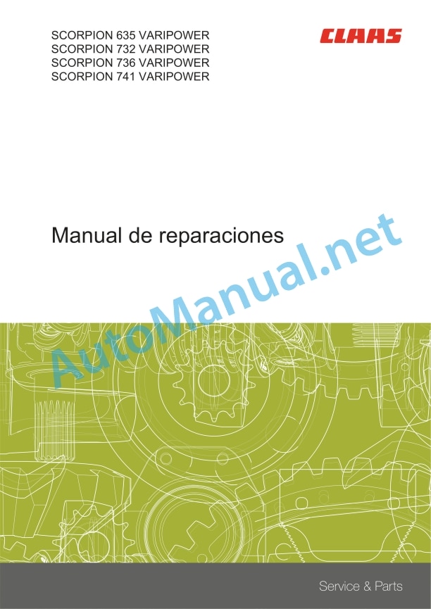
SCORPION 635 VARIPOWERSSCORPION 732 VARIPOWERSCORPION 736 VARIPOWERSSCORPION 741 VARIPOWER
Introduction
Information regarding the instruction manual
Manual validity
Information regarding this repair manual
Using the manual
Breakdown of the structure of constructive groups
Search and find
Direction signs
Measurement units
General repair instructions
Technical instructions
Indications for correct repair
Self-locking screws
Liquid screw insurance
Steel roller chains
connecting link
Type E connecting link with spring
Type G connecting link with wire
S type connecting link with pins
Tapered ring joints
Disassembly
Mounting
Head key joints
Disassembly
Mounting
Bearings with tension ring
Disassembly
Mounting
Bearing with tensioner sleeve
Disassembly
Mounting
Tension bushing
Disassemble
Disassembly version A
Disassembly version B
Tension bushing version A
Tension bushing version B
Safety rings
Screw connections with adjustment ring
Screw connections with non-sealed adjusting ring
Screw connections with sealing cone
Hydraulic hoses
Laying of hoses
Membrane accumulator (pressure accumulator) complying with factory regulations CLAAS CN 24 0403
Signaling
Operational means
Service and assembly
Modification of gas filling
special tool
Joint surface work
Replacement parts
Consumables
Tightening torques
Tightening torques for metric normal thread and metric fine thread
Tightening torques for hydraulic bolted connections with cutting ring
Tightening torques for fittings with tapered seal connection and hydraulic connections with soft seal ring
Tightening torques for SDS form B and E hydraulic threaded fittings
Tightening torques for SDE form H hydraulic threaded fittings, adjustable
Tightening torques for oscillating hydraulic threadings
Tightening torques for hollow screws (with copper gasket)
Tightening torques for brake pipe threading
Tightening torques for pipe supports with O-ring and union nuts
Tightening torques for helical thread clamps
Tightening torques for hose clamps with round bolt
Security
Recognize warning signs
Danger symbols
Safety instructions
Graphic danger symbols and warning indications
Requirements for technical personnel
Children in danger
Machine danger zones
Accompanying instructor during work
Risk of injury due to rotating shafts
Construction modifications to the machine
Optional equipment and spare parts
Control of the machine running
Technical status
Comply with technical limit values
Danger from machine parts during coasting
Keep protective devices operational
Personal protective equipment
Wear appropriate clothing
Remove dirt and loose objects
Park the machine safely
Unsuitable consumables
Safe handling of consumables and auxiliary materials
Environmental protection and waste disposal
Keep the cabin free of chemicals
Fire prevention
Lethal electrical shock due to overhead power lines and lightning strikes
Current discharge through the electrical installation
Noise can cause health damage
Prestressed machine parts
Liquids under pressure
Air under presure
Toxic exhaust gases
Hot surfaces
Safe ascent and descent
Only work on the stopped machine
Dangers in repair work
Machine parts and lifted loads
Danger due to welding work
Check and charge the battery
Emergency Preparations
CCN Explanation
CCN (CLAAS Component Number)
General indications
Electrical regulations
Hydraulic regulations
CCN (CLAAS Component Number)
01 Engine
0102 Complete component
Diesel engine
Technical instructions
Preparation for work
Disassemble
0125 Fuel/injection system
Fuel tank
Technical instructions
Disassemble
tank sensor
Technical instructions
Preparation for work
Disassemble
fuel pump
Technical instructions
Disassemble
fuel prefilter
Technical instructions
Disassemble
0135 Cooling system
compensation deposit
Technical instructions
Disassemble
engine radiator
Technical instructions
Disassemble
fan motor
Technical instructions
Disassemble
Fan valve block
Technical instructions
Disassemble
Fan valve block
Technical instructions
Disassemble
0140 Exhaust gas system
exhaust gas pipe
Technical instructions
Disassemble
0145 Air suction
air filter box
Technical instructions
Disassemble
Intercooler
Technical instructions
Disassemble
0150 Engine coupled parts
Strap cover
Technical instructions
Preparation for work
Disassemble
Starting motor
Disassemble
Generator
Disassemble
pressure air compressor
Technical instructions
Disassemble
0155 Engine adjustment
Accelerator pedal
Technical instructions
Disassemble
0165 Exhaust gas aftertreatment
Exhaust gas aftertreatment, general information
Preparation for work
special tool
Check the purity of the urea solution
Control the density of the urea solution
Diesel oxidation catalyst
Technical instructions
Disassemble
diesel particulate filter
Technical instructions
Disassemble
Mixed section
Technical instructions
Disassemble
Metering valve
Technical instructions
Disassemble
SCR catalyst
Technical instructions
Disassemble
urea tank
Technical instructions
special tool
Disassemble
urea extraction unit
Technical instructions
special tool
Disassemble
urea pump
Technical instructions
Disassemble
02 Gears / clutch / cardan shaft
0210 Vibration dampers
Vibration damper
Technical instructions
Disassemble
0230 Mechanical gear
fast gearbox
Technical instructions
Preparation for work
Disassemble
Replacing the drive flange
0238 Gearbox control/drive
Control cover
Technical instructions
Disassemble
0260 Cardan shaft
cardan shafts
Technical instructions
Preparation for work
Disassemble
Disassemble
03 Chassis
0325 Front drive steering axle
Front drive axle
Technical instructions
Disassemble
planetary gear
Technical instructions
special tool
Disassemble
wheel hub
Technical instructions
Preparation for work
special tool
Disassemble
shaft body
Technical instructions
special tool
Disassemble
Bevel pinion drive
Technical instructions
Preparation for work
special tool
Differential
Technical instructions
Preparation for work
special tool
Disassemble
0330 Rear drive steering axle
Rear drive steering axle
Technical instructions
Disassemble
planetary gear
wheel hub
shaft body
Technical instructions
special tool
Disassemble
Drive with bevel pinion
Differential
0335 Propulsion
Hydraulic propulsion pump
Technical instructions
Disassemble
04 Brake
0405 Service brake
Service brake
Technical instructions
Preparation for work
Disassemble
Service brake hydraulic cylinder
Technical instructions
Disassemble
0415 Parking brake
Parking break
Assembly instructions
Mechanically release the parking brake
0420 Trailer air brake equipment
Compressed air tank
Technical instructions
Disassembly of the front compressed air tank
Mounting the front compressed air tank
Disassembly of the rear compressed air tank
Mounting the rear compressed air tank
05 Address
0505 Address
Steering column
Technical instructions
Disassemble
Steering column
Technical instructions
Disassemble
steering unit
Technical instructions
Disassemble
Hydraulic steering cylinder
Technical instructions
Preparation for work
Disassemble
Adjust the ride
Steering angle adjustment
lock block
Technical instructions
Disassemble
Bleeding the steering hydraulic system
06 Lifting device
0620 Telescopic arm
Telescopic arm
Technical instructions
special tool
Disassemble
Telescopic arm for emergency lifting
Telescopic arm for emergency lowering
Telescopic projection
Technical instructions
Disassemble
Energy chain
Technical instructions
Disassemble
Laying the ducts
scratching post
Technical instructions
Disassemble
Skid plates
Technical instructions
Preparation for work
Assembly instructions
Disassemble
Tool holders
Technical instructions
special tool
Disassemble
Tool holders
Technical instructions
special tool
Disassemble
Hydraulic cylinder raise
Technical instructions
special tool
Disassemble
Hydraulic cylinder raise
Technical instructions
special tool
Disassemble
Compensation hydraulic cylinder
Technical instructions
special tool
Disassemble
Hydraulic cylinder extension
Technical instructions
Disassemble
Only with oil leak pipe:
Only with oil leak pipe:
Only with oil leak pipe:
Hydraulic cylinder dump
Technical instructions
special tool
Disassemble
Hydraulic cylinder quick change lock
Technical instructions
special tool
Disassemble
Travel angle sensor
Technical instructions
Disassemble
Rollover angle sensor
Technical instructions
Disassemble
07 Towing device
0705 Trailer support
trailer hitch
Technical instructions
Disassemble
Height-adjustable trailer hitch
Technical instructions
Disassemble
0720 Hitch
Technical instructions
Disassemble
Remove the B67-LWT sensor
Mount the B67-LWT sensor
Remove the bolt
Mount the bolt
08 Drives
0800 Drive diagram
Drive scheme
09 Hydraulics
0905 Hydraulic oil tank
Hydraulic oil tank
Technical instructions
special tool
Disassemble
Create underpressure in the hydraulic oil tank
Stop generating negative pressure in the hydraulic oil tank
0907 Hydraulic oil cooler
Hydraulic oil cooler
0910 Bombs
Hydraulic pump of working hydraulic system
Technical instructions
Disassemble
Gear Pump Hydraulic Pump
Technical instructions
Disassemble
0915 Hydraulic pipes
Anti-vibration system pressure accumulator
Technical instructions
Disassemble
0920 Valves
Valve block of the hydraulic braking system
Technical instructions
Disassemble
Direction Types Valve
Technical instructions
Disassemble
Control circuit valve block 3
Technical instructions
Disassemble
Hitch valve block
Technical instructions
Disassemble
Working hydraulic system valve block
Technical instructions
Disassemble
Working hydraulic system valve block
Technical instructions
Disassemble
Load holding valve
Technical instructions
Disassemble
10 Install. electrical/electronic
1005 Power supply
Technical instructions
Disassemble
Battery separator switch
Technical instructions
Disassemble
1010 Central electrical system
central electrical system
Technical instructions
Disassemble
Connector Overview
Technical instructions
Disassembly of the A46-LWT
Assembly of the A46-LWT
Disassembly of the A30-LWT
Assembly of the A30-LWT
Disassembly of the A50-LWT
Assembly of the A50-LWT
Disassembly of the A40-LWT
Assembly of the A40-LWT
Load sensor
Technical instructions
Preparation for work
Disassemble
1035 Multifunctional handle/lever
Joystick
Technical instructions
Disassemble
Inching joystick
Technical instructions
Disassemble
hand throttle joystick
Technical instructions
Disassemble
Control circuit joystick 4
Technical instructions
Disassemble
Indicator unit
Technical instructions
Disassemble
Steering type dashboard
Technical instructions
Disassemble
DMS valuation electronics
Technical instructions
Disassemble
12 Driver’s cab/platform
1210 Cabin
Technical instructions
Disassemble
Window cleaning agent tank
Technical instructions
Disassemble
Front windshield wiper
Technical instructions
Disassemble
rear wiper
Technical instructions
Disassemble
1230 Seat
Operator seat
Technical instructions
Disassemble
1235 Cabin heating
Air conditioning-heating box
Technical instructions
Disassemble
Heat exchanger
Technical instructions
Disassemble
Technical instructions
Disassemble
Cabin air filter
Technical instructions
Disassemble
1240 Air conditioning equipment
General instructions on air conditioning equipment
Empty the air conditioning unit
Fill the air conditioning unit
Air conditioning compressor
Technical instructions
Disassemble
Vaporizer
Technical instructions
Disassemble
Condenser
Technical instructions
Disassemble
Filter dryer
Technical instructions
Disassemble
75 Central lubrication
7500 General indications of the central lubrication system
Central lubrication system, general instructions
special tool
7505 Container, pump
Tank and pump
Technical instructions
Disassemble
Remove the transport plunger
Transport plunger assembly
7515 Lubrication/piping equipment
Grease hoses
special tool
80 Attached parts, machine casing
8005 Frame / table
Crankcase
Technical instructions
Assembly instructions
8020 Guardrail / protective devices
Run-in protection device
Technical instructions
Disassemble
8025 Coverings / hoods
engine hood
Technical instructions
Disassemble
8030 Mudguard
Mudguard
Technical instructions
Disassemble
95 Maintenance parts summary
9599 Maintenance work
Place the machine in maintenance position
Checking the tightness of the diesel engine
Checking the diesel engine mounts
Changing the fuel filter filter cartridges
Preparation for work
fuel prefilter
fine fuel filter
Change the diesel engine oil.
Preparation for work
Change the diesel engine oil filter
Preparation for work
Checking the belt (R01) of the diesel engine
Changing the belt (R01) of the diesel engine
Checking the tightness and condition of the refrigerant equipment
Coolant fluid change
Preparation for work
Check the antifreeze protection of the coolant
Preparation for work
Correct the concentration of antifreeze protection
Checking the suction system and exhaust gas equipment
Checking the tight fit of the compressed air compressor
Checking the belt (R03) of the compressed air compressor
Changing the belt (R03) of the compressed air compressor
Checking the diesel engine sensor cable connection
Changing the urea pump filter
Propulsion gear oil change
Preparation for work
Check and measure propulsion
Check the axle oil level
differential gear
wheel hub
Change the axle oil
Preparation for work
differential gear
wheel hub
Checking the tightening torque of the axle fixing screws
Checking the wear of the brake linings
Cleaning the external compressed air tank
Checking the tightness of the pneumatic brake equipment
Checking the fill level of the antifreeze pump for the air brake system
Check and measure the brake system
Check and measure the guidance system
Checking the rear friction plates for wear and tight fit
Checking the tightness of the hydraulic system
Change hydraulic oil
Preparation for work
Changing the hydraulic tank ventilation filter
Changing the filter element of the hydraulic tank return filter
Changing the power circuit pressure filter
Check and measure the working hydraulic system
Checking that the battery connections are securely seated
Check the battery fluid level
Checking the condition and correct routing of the battery exhaust pipe
Dryer unit control
Check heating and air conditioning equipment
Cleaning the fresh air filter
Checking the water outlet valve of the air conditioning system
Checking the belt (R02) of the air conditioning compressor
Changing the belt (R02) of the air conditioning compressor
John Deere Repair Technical Manual PDF
John Deere Repair Technical Manual PDF
John Deere Repair Technical Manual PDF
John Deere Repair Technical Manual PDF
John Deere PowerTech M 10.5 L and 12.5 L Diesel Engines COMPONENT TECHNICAL MANUAL CTM100 10MAY11
John Deere Repair Technical Manual PDF
John Deere Repair Technical Manual PDF
John Deere Repair Technical Manual PDF
John Deere Parts Catalog PDF
John Deere Tractors 6300, 6500, and 6600 Parts Catalog CQ26564 (29SET05) Portuguese


