Claas Scorpion 7044 (K24) Telehandlers Technical System EN
$300.00
- Model: Scorpion 7044 (K24) Telehandlers
- Type Of Manual: Technical System
- Language: EN
- Format: PDF(s)
- Size: 367 MB
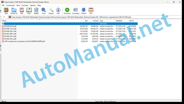
File List:
00 0288 505 0.pdf
00 0300 119 2.pdf
00 0300 384 1.pdf
00 0301 888 1.pdf
00 0302 343 1.pdf
00 0302 565 2.pdf
CHP-numbers for connectors CLAAS HARNESS PARTS.pdf
00 0288 505 0.pdf:
Diesel engineDEUTZ TD / TCD 3.6 L4 Tier 4f
Table of contents
Introduction
Validity of manual
Validity of manual
About this Technical Systems documentation
Symbols and notes
Further useful information
List of abbreviations
General information
Marking of warnings and hazard prevention notes
Safety routines
First-aid measures
CCN explanation
CCN (CLAAS Component Number)
CLAAS electric systems standard
Overview
KRAMER ALLRAD electric systems standard (KCN standard)
Overview
CCN (CLAAS Component Number)
01 Engine
0102 Complete component
Complete component
TDC 3.6 L4 f engine, service page on the right
Left side of TDC 3.6 L4 f engine
Engine TDC 3.6 L4 f exhaust gas treatment system
Engine number and serial number of crank case
DEUTZ diesel engine identification plate
0110 Engine housing
Engine housing
Crankcase venting
Valve cover with oil separator
0115 Engine unit
Cylinder arrangement
0120 Cylinder head / Valves / Idler gear
Gear drive
Gear drive
Gearwheel housing
Valve train
Oil supply of hydraulic tappets and rocker arms
V-belt pulley / sensor wheel
V-belt pulley expansion pins / sensor wheel
Fixing the V-belt pulley to the crankshaft
0125 Injection / Fuel system
Injection / fuel system
Fuel system diagram
Function description of fuel system
Overview of injection system
Injectors
Function of injectors
Description of injector function
Bosch CP4.1 high-pressure pump
Control block (FCU)
Rail pressure relief valve
0130 Lubricating oil system
Lubricating oil system
Overview of components
Layout of lubrication oil system
Lubrication pump
Oil pressure control valve
Pressure relief valve
0135 Cooling system
Cooling system
Coolant diagram
Description of function
Thermostat
Coolant pump union
Coolant pump
Coolant drain
0140 Exhaust system
Exhaust gas recirculation
Exhaust gas recirculation (EGR) system overview
Description of function
Exhaust gas recirculation cooler (EGR cooler)
Exhaust gas recirculation (EGR) control valve
Exhaust gas recirculation (EGR) reed valve
Charge air sensor, TDC 3.6 L4 engine (DOC)
Exhaust system
Turbocharging
0155 Engine control
Diesel engine 3.6 monitoring, control
Measured values table
Description of function
0165 Exhaust gas aftertreatment
Exhaust gas treatment system (EAT)
Overview of functions
Description of function
Overview of exhaust gas treatment
Mixing section
Description of function
Dosing unit
Description of function
NOx sensors and NOx electronic unit
Description of function
Exhaust back-pressure sensor
Description of function
Temperature sensors
Withdrawal unit
Conveying module
Components in conveying module (M029-KRA)
Description of function
Tank heater solenoid valve
Description of function
Ambient air temperature sensor
Description of function
Urea heater
Overview of functions
Withdrawal unit
Description of function
Dosing unit
Description of function
Tank heater solenoid valve
Description of function
Diesel oxidation catalyst (DOC)
Design of diesel oxidation catalytic converter (DOC)
Description of function
0197 Test/Measurement/Setting
Parametrising the IMA code
Parametrising the IMA code after replacing the injectors
Description
Reading the IMA code
Parametrizing the IMA code with the CDS
Resetting the injector correction values
Resetting the injector correction values with the CDS
Reading out and resetting the rail pressure relief valve
Reading out the openings of rail pressure relief valve (B022-KRA) and resetting the counter
0198 Problem / Remedy
High-pressure pump service
10 Electrical / Electronic equipment
1012 Modules / sensors
N005-KRA – Diesel engine electronics DEUTZ 3.6 part 1/9
Key to diagram
Key to diagram
N005-KRA – Diesel engine electronics DEUTZ 3.6 part 2/9
Key to diagram
Key to diagram
N005-KRA – Diesel engine electronics DEUTZ 3.6 part 3/9
Key to diagram
Key to diagram
N005-KRA – Diesel engine electronics DEUTZ 3.6 part 4/9
Key to diagram
Key to diagram
N005-KRA – DEUTZ 3.6 diesel engine electronics part 5/9
Key to diagram
Key to diagram
N005-KRA – Diesel engine electronics DEUTZ 3.6 part 6/9
Key to diagram
Key to diagram
N005-KRA – Diesel engine electronics DEUTZ 3.6 part 7/9
Key to diagram
Key to diagram
N005-KRA – Diesel engine electronics DEUTZ 3.6 part 8/9
Key to diagram
Key to diagram
N005-KRA – Diesel engine electronics DEUTZ 3.6 part 9/9
Key to diagram
Key to diagram
1085 Networks
CAN bus – K24 (416-11)
Description of function
1080 Electrical circuit diagram
Electric system circuit diagrams (SCM)
SCM 01 Diesel engine diagnosis
Key to diagram
Key to diagram
SCM 02 Exhaust treatment
Key to diagram
Key to diagram
SCM 03 Diesel engine, vehicle side
Key to diagram
Key to diagram
SCM 04 Diesel engine, engine side
Key to diagram
Key to diagram
SCM 05 Diesel engine cooling
Key to diagram
Key to diagram
92 Diagnosis
9220 Error codes engine (J1939)
FMI fault code (Failure Mode Indicator)
FMI 00 (Signal too high)
FMI 01 (Signal too low)
FMI 02 (Erratic signal)
FMI 03 (Voltage too high)
FMI 04 (Voltage too low)
FMI 05 (Current too low)
FMI 06 (Current too high)
FMI 07 (Mechanical failure)
FMI 08 (Abnormal frequency signal)
FMI 09 (Communication error)
FMI 10 (Rate of signal change too fast)
FMI 11 (multiple faults)
FMI 12 (ECU defective)
FMI 13 (Signal outside of calibration range)
FMI 16 (Parameter not available)
FMI 17 (ECU not responding)
FMI 18 (Power supply failure)
FMI 19 (Software conditions not met)
FMI 95 (no signal change)
FMI 96 (CAN Bus system defective)
FMI 97 (Erratic condition)
FMI 98 (Warning)
FMI 99 (Info)
DEUTZ (DTC) diesel engine and ISO J1939 (SPN) fault code list
Description of function
Position of components
Electric system
B Sensors, signal transducers
G Power supply
H Indicator lights
M Drives
N Control unit
Y Solenoid coil
00 0300 384 1.pdf:
DEUTZ TD / TCD 3.6 L4 diesel engine
Table of contents
Introduction
Validity of manual
Validity of manual
General information
Technical Systems documentation and other sources of information
Importance of Technical Systems documentation
Personnel qualification and organization
Requirements made on all persons working with the machine
Alterations on the machine
Structural alterations
Additional equipment and spare parts
Requirements made on spare parts
Workplaces and persons travelling on the machine
Control of machine while running
Instructors travelling along during fieldwork
Technically flawless condition
Technically flawless condition of machine
Danger from damage to the machine
Respecting technical limit values
Hazard areas of the machine
Hazard areas
Hitching of machine to implement or trailer
Standing between machine and trailer
Hazard from engaged drive
Danger from machine parts that continue rotating
Safety devices
Keeping safety devices functional
Personal protective equipment
Personal protective equipment
Wearing suitable clothing
Safety markings
Keeping safety decals legible
Road safety
Hazards when driving on the road and on the field
Stability hazard
Preparing the machine for road travel
Parking the machine safely
Unsupervised parking
Keeping the machine free of foreign objects
Operating utilities
Unsuitable operating utilities
Safe handling of operating and auxiliary utilities
Fuel is detrimental to your health
Refrigerant is detrimental to your health
Environmental protection and disposal
Chemicals
Keeping the cab free of chemicals
Hazards from the work environment
Fire hazard
Potentially fatal electric shock from overhead lines
Behaviour in case of voltage flash-over due to overhead lines and when lightning strikes
Sources of hazards on the machine
Electric shock from electric system
Noise may damage your health
Vibrations may damage your health
Liquids under pressure
Compressed air
Toxic exhaust gases
Hot surfaces
Hazards when accessing and getting off the machine
Safe access and getting off
Hazards when working on the machine
Work only on the machine after shutting it down
Inspection, adjusting, maintenance and repair work
Raised machine parts and loads
Danger from welding work
Danger from painting work
Work on the electric system
Work on the diesel engine
Handling fuels
Handling hot liquids
Safety routines
First-aid measures
List of abbreviations
01 Engine
0102 Complete component
Complete component
TDC 3.6 L4 (DOC) engine, right service side
TDC 3.6 L4 (DOC) engine, left service side
TDC 3.6 L4 (CRT) engine, right service side
TDC 3.6 L4 (CRT) engine, left service side
Engine number and serial number of crank case
DEUTZ diesel engine identification plate
0110 Engine housing
Engine housing
Crankcase venting
Valve cover with oil separator
0115 Engine unit
Cylinder arrangement
0120 Cylinder head / Valves / Idler gear
Gear drive
Gear drive
Gearwheel housing
Valve train
Oil supply of hydraulic tappets and rocker arms
V-belt pulley / sensor wheel
V-belt pulley expansion pins / sensor wheel
Fixing the V-belt pulley to the crankshaft
0125 Injection / Fuel system
Injection / fuel system
Fuel system diagram
Injection system
Function of injectors
Description of injector function
Replacing the injectors
Description of function
IMA code
Parametrizing the IMA code with the CDS
Reset injector correction values with the CDS (1 of 2)
Reset injector correction values with the CDS (2 of 2)
Bosch CP4.1 high-pressure pump
Control block (FCU)
High-pressure pump service
Rail pressure relief valve
Reading out the number of openings of the rail pressure relief valve and resetting the counter with the CDS (1 of 2)
Reading out the number of openings of the rail pressure relief valve and resetting the counter with the CDS (2 of 2)
0130 Lubricating oil system
Lubricating oil system
Lubricating oil circuit
Lubricating oil system
Lubrication pump
Pressure relief valve
Oil pressure control valve
0135 Cooling system
Cooling system
Coolant diagram
Thermostat
Coolant pump union
Coolant pump
Coolant drain
0140 Exhaust system
Exhaust system
Turbocharging
Exhaust gas recirculation (EGR) system overview
Exhaust gas recirculation cooler (EGR cooler)
Exhaust gas recirculation (EGR) control valve
Exhaust gas recirculation (EGR) reed valve
Charge air sensor, TDC 3.6 L4 engine (DOC)
0155 Engine control
Engine monitoring and control
Note: regarding Technical Systems documentation
0165 Exhaust gas aftertreatment
Diesel oxidation catalytic converter (DOC)
Exhaust gas treatment with diesel oxidation catalytic converter (DOC)
Design of diesel oxidation catalytic converter (DOC)
Exhaust system
Turbocharging
Exhaust gas recirculation (EGR) system overview
Exhaust gas recirculation cooler (EGR cooler)
Exhaust gas recirculation (EGR) control valve
Exhaust gas recirculation (EGR) reed valve
Charge air sensor, TDC 3.6 L4 engine (DOC)
10 Electrical / Electronic equipment
1012 Modules / sensors
N005-KRA – Diesel engine electronics part 1/7
Key to diagram
Key to diagram
N005-KRA – Diesel engine electronics part 2/7
Key to diagram
Key to diagram
N005-KRA – Diesel engine electronics part 3/7
Key to diagram
Key to diagram
N005-KRA – Diesel engine electronics part 4/7
Key to diagram
Key to diagram
N005-KRA – Diesel engine electronics part 5/7
Key to diagram
Key to diagram
N005-KRA – Diesel engine electronics part 6/7
Key to diagram
Key to diagram
N005-KRA – Diesel engine electronics part 7/7
Key to diagram
Key to diagram
DEUTZ TCD 3.6 L4 DOC sensors
DEUTZ TCD 3.6 L4 DOC engine electronics and sensors
1085 Networks
Engine – machine BUS system (CAN)
Note: regarding Technical Systems documentation
1080 Electrical circuit diagram
Electric system power cabling circuit diagrams
SHEET 1 power cabling
Key to diagram
SHEET 2 power cabling
Key to diagram
Electric system unit cabling circuit diagrams
SHEET 1 unit cabling
Key to diagram
Engine wiring loom electric system circuit diagrams
SHEET 2 engine wiring loom
Key to diagram
SHEET 3 engine wiring loom
Key to diagram
SHEET 4 engine wiring loom
Key to diagram
SHEET 5 engine wiring loom
Key to diagram
Exhaust gas post-treatment electric system circuit diagrams
SHEET 1 exhaust gas post-treatment
92 Diagnosis
9220 Error codes engine (J1939)
FMI failure code (Failure Mode Indicator)
FMI 00 (Signal too high)
FMI 01 (Signal too low)
FMI 02 (Erratic signal)
FMI 03 (Voltage too high)
FMI 04 (Voltage too low)
FMI 05 (Current too low)
FMI 06 (Current too high)
FMI 07 (Mechanical failure)
FMI 08 (Abnormal frequency signal)
FMI 09 (Communication error)
FMI 10 (Rate of signal change too fast)
FMI 11 (multiple faults)
FMI 12 (ECU defective)
FMI 13 (Signal outside of calibration range)
FMI 16 (Parameter not available)
FMI 17 (ECU not responding)
FMI 18 (Power supply failure)
FMI 19 (Software conditions not met)
FMI 95 (no signal change)
FMI 96 (CAN Bus system defective)
FMI 97 (Erratic condition)
FMI 98 (Warning)
FMI 99 (Info)
DEUTZ (DTC) diesel engine and ISO J1939 (SPN) fault code list
Description of function
00 0302 343 1.pdf:
PROFI CAM 3
Table of contents
General information
Marking of warnings and hazard prevention notes
First-aid measures
CCN explanation
CCN (CLAAS Component Number)
Electric system standard
Overview
Hydraulic system standard
Overview
CCN (CLAAS Component Number)
10 Electrical / Electronic equipment
1030 Board computer / Indicators
Camera system
Description of function
1097 Testing / Measuring / Adjusting
Testing / measuring / adjusting the PROFI CAM
Checking the fuse in the video channel select box (C102)
Testing the video camera connector (C055)
1098 Fault / remedy
Fault / remedy PROFI CAM
The video monitor (C101) shows no image or cannot be switched on (indicator light fails to light up)
Video monitor (C102) displays a blue image either permanently or temporarily
The video monitor image is blurred
Replacing the fuse in the video channel select box (C102)
Connection and connecting cable with video camera (C055)
00 0302 565 2.pdf:
Sensor system
Table of contents
CCN explanation
CCN (CLAAS Component Number)
Electric system standard
Overview
Hydraulic system standard
Overview
CCN (CLAAS Component Number)
Introduction
Safety rules
Safety and hazard information
10 Electrical / Electronic equipment
1097 Testing / Measuring / Adjusting
Test report of the angle sensor (0011780.x)
Application of test report
Required tools
Test report of the angle sensor (0011780.x)
Testing / Measuring / Adjusting of angle sensor (0011780.x)
1. Reason for test
2. Mechanical test of angle sensor
3. Electric test with CDS
4. Electric test with multimeter
5. Mechanical test of connecting cable
Completing the machine
Test report of position and speed sensors
Application of test report
Required tools
Sensor variants
Part numbers of speed sensors
Part number of position sensor
Test report of position and speed sensors
Testing / measuring / adjusting of position and speed sensors
1. Reason for test
2. Mechanical test
3. Electric test with CDS
4a. Installation dimensions
Check of installation dimension
Installation dimensions of gearbox speed sensor (0011 799.x) and cam speed sensor (0011 810.x)
Installation dimension of position sensor (0011 815.x)
4b. Installation position
Centring of sensor
Metal-free zone
5. Electric test with multimeter
Voltage measurement
Direction of rotation and speed sensor (0011 605.x)
Measured values table
6. Mechanical test of connecting cable
Completing the machine
Test report of the urea sensor (00 0773 207 x)
Application of test report
Required tools
Parts number of the urea sensor
Test report of the urea sensor
Testing / measuring / adjusting urea sensor
1. Reason for test
2. Mechanical test
3. Mechanical test of connecting cable
4. Electric test with multimeter
5. Component test with the CDS
CHP-numbers for connectors CLAAS HARNESS PARTS.pdf:
CLAAS HARNESS PARTS
Table of contents
10 Electrical / Electronic equipment
1081 Overview of connectors
CLAAS HARNESS PARTS (CHP)
John Deere Repair Technical Manual PDF
John Deere Diesel Engines POWERTECH 2.9 L Component Technical Manual CTM126 Spanish
John Deere Repair Technical Manual PDF
John Deere Repair Technical Manual PDF
John Deere 16, 18, 20 and 24HP Onan Engines Component Technical Manual CTM2 (19APR90)
John Deere Parts Catalog PDF
John Deere Tractors 7500 Parts Catalog CPCQ26568 30 Jan 02 Portuguese
John Deere Repair Technical Manual PDF
John Deere Repair Technical Manual PDF
John Deere Application List Component Technical Manual CTM106819 24AUG20
John Deere Repair Technical Manual PDF
John Deere DF Series 150 and 250 Transmissions (ANALOG) Component Technical Manual CTM147 05JUN98
John Deere Repair Technical Manual PDF
John Deere Repair Technical Manual PDF

