Claas Scorpion 7045 7040 (K14) Telehandlers Assembly Instruction EN
$50.00
- Model: Scorpion 7045 7040 (K14) Telehandlers
- Type Of Manual: Assembly Instruction
- Language: EN
- Format: PDF(s)
- Size: 34.8 MB
File List:
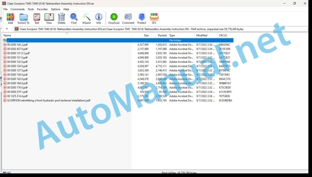
00 0290 143 2.pdf
00 0292 437 0.pdf
00 0300 131 0 2.pdf
00 0300 131 0.pdf
00 0300 132 0.pdf
00 0300 134 0.pdf
00 0300 137 0.pdf
00 0300 139 0.pdf
00 0300 143 0.pdf
00 0300 164 0.pdf
00 0300 176 0.pdf
00 0300 374 1.pdf
00 1325 214 4.pdf
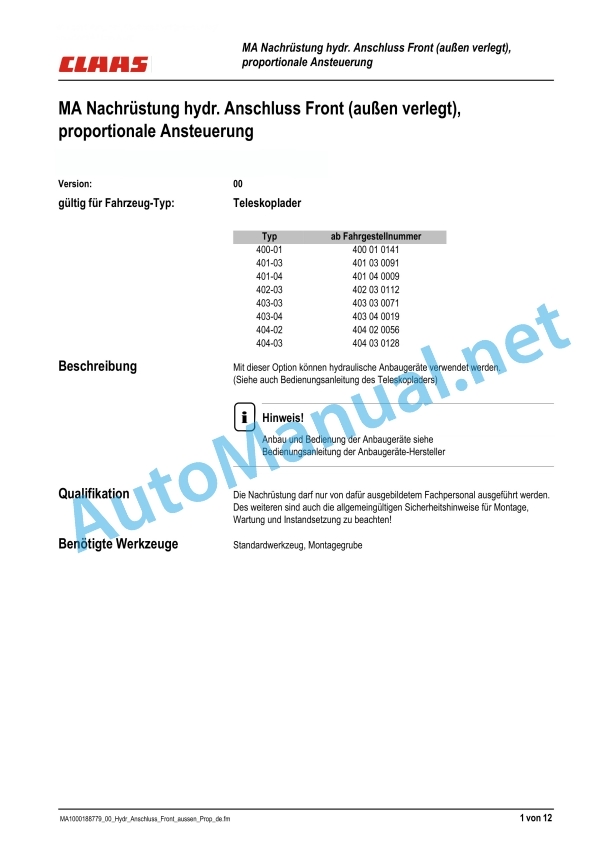
SCORPION retrofitting a front hydraulic port (external installation).pdf
00 0300 131 0 2.pdf:
Montageanleitung – Schnellganggetriebe Version I+II mit constant Zusatzmotor, durch Schnellganggetriebe Version III austauschen
Qualification
Benötigte Werkzeuge
Schnellganggetriebe Version I, durch Schnellganggetriebe Version III austauschen
Schnellganggetriebe Version II, durch Schnellganggetriebe Version III austauschen
Vorbereitungsarbeiten
Getriebe dismantling
Overview: Getriebe
Vormontage Getriebe (new)
Assembly Verschraubungen Prüfanschlüsse
Zusatzmotor mounted
Getriebe assembly (new)
Inbetriebnahme
Assembly instructions for replacement of version I + II high-speed gearbox with auxiliary fdsplacement motor, by version III high-speed gearbox
Qualification
Necessary tools
Replacement of version I by version III high-speed gearbox
Replacement of version II by version III high-speed gearbox
Preparatory work
Removing the gearbox
Gearbox overview
Pre-assembly the gearbox (new)
Installing the threaded fittings of the test connections
Install the auxiliary motor
Installing the new gearbox
Putting into operation
Assembly instructions for replacing a version I + II of the overdrive gearbox with additional constant displacement motor, with a version III
Qualification
Necessary tools
Replacement of a version I by a version III of the overdrive gearbox
Replacement of a version II by a version III of the overdrive gearbox
Preliminary activities
Removing the box
Box Overview
Box pre-assembly (new)
Mounting the screw connections of the measuring sockets
Mount the additional motor
Assembly of the box (new)
Start-up
00 0300 131 0.pdf:
Montageanleitung – Schnellganggetriebe Version I+II mit constant Zusatzmotor, durch Schnellganggetriebe Version III austauschen
Qualification
Benötigte Werkzeuge
Schnellganggetriebe Version I, durch Schnellganggetriebe Version III austauschen
Schnellganggetriebe Version II, durch Schnellganggetriebe Version III austauschen
Vorbereitungsarbeiten
Getriebe dismantling
Overview: Getriebe
Vormontage Getriebe (new)
Assembly Verschraubungen Prüfanschlüsse
Zusatzmotor mounted
Getriebe assembly (new)
Inbetriebnahme
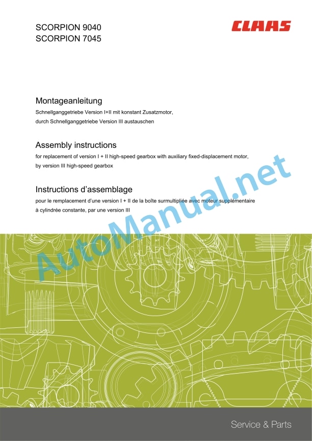
Assembly instructions for replacement of version I + II high-speed gearbox with auxiliary fixed-displacement motor, by version III high-speed gearbox
Qualification
Necessary tools
Replacement of version I by version III high-speed gearbox
Replacement of version II by version III high-speed gearbox
Preparatory work
Removing the gearbox
Gearbox overview
Pre-assembly the gearbox (new)
Installing the threaded fittings of the test connections
Install the auxiliary or
talling the new gearbox
Putting into operation
Assembly instructions for replacing a version I + II of the overdrive gearbox with additional constant displacement motor, with a version III
Qualification
Necessary tools
Replacement of a version I by a version III of the overdrive gearbox
Replacement of a version II by a version III of the overdrive gearbox
Preliminary activities
Removing the box
Box Overview
Box pre-assembly (new)
Mounting the screw connections of the measuring sockets
Mount the additional motor
Assembly of the box (new)
Start-up
00 0300 132 0.pdf:
Montageanleitung Schnellganggetriebe Version I+II durch Schnellganggetriebe Version III austauschen
Qualification
Benötigte Werkzeuge
Übersicht: Schnellganggetriebe
Schnellganggetriebe Version I, durch Schnellganggetriebe Version III austauschen
Schnellganggetriebe Version II, durch Schnellganggetriebe Version III austauschen
Vorbereitungsarbeiten
Getriebe dismantling
Vorntage Getebe (new)
Getriebe assembly
Inbetriebnahme
Assembly instructions for replacement of version I + II by version III high-speed gearbox
Qualification
Necessary tools
High-speed gearbox (overview)
Replacement of version I by version III high-speed gearbox
Replacement of version II by version III high-speed gearbox
Preparatory work
Removing the gearbox
Pre-assembly the gearbox (new)
Installing the gearbox
Putting into operation
Assembly instructions for replacing a version I + II with a version III of the overdrive box
Qualification
Necessary tools
Overview of the overdrive box
Replacement of a version I by a version III of the overdrive gearbox
Replacement of a version II by a version III of the overdrive gearbox
Preliminary activities
Removing the box
Box pre-assembly (new)
Box assembly
Start-up
00 0300 134 0.pdf:
MA Umrüstung Steuergerät von 5310 auf HDS34
Qualification
Benötigte Werkzeuge
Steuergerät ersetzt durch:
Pie: Disassemborhandenes Steuergerät
Picture: Steuergerät Oberseite (Verschraubungen montiert)
Picture: Steuergerät Oberseite (verschlaucht)
Picture: Steuergerät Oberseite (verschlaucht)
Mounting Steuergerät Unterseite (Ausführung: Hydraulischer Anschluss Heck)
Assembly Steuergerät Unterseite
Instructions Assembly
Disassembly: Steuergerät
Assembly: Steuergerät
Inbetriebnahme
Assembly instructions for replacing a 5310 control by an HDS34 control valve
Qualification
Necessary tools
Control valve replaced by:
Figures: removing the existing control valve
Figures: control valve top side (screw connections fitted)
Figures: control valve top side (hoses fitted)
Figures: control valve top side (hoses fitted)
Control valve assembly, lower side (rear hydraulic port version)
Assembly, control valve lower side
Preparatory work
Removing the control valve
Installing the control valve
Putting into operation
Assembly instructions for replacing a 5310 distributor with an tributor
Quali Necessary tools
Distributor replaced by:
Figures: removal of the existing distributor
Figures: upper face of the distributor (mounted screws)
Figures: upper face of the distributor (hoses installed)
Figures: upper face of the distributor (hoses installed)
Mounting the distributor, underside (version: rear hydraulic connection)
Assembly, underside of the distributor
Preliminary activities
Removing the distributor
Mount the distributor
Start-up
00 0300 137 0.pdf:
Montageanleitung Anbau Bolzen Schnellwechselplatte
Beschreibung
Qualifikation
Benötigte Werkzeuge
Vorbereitung Montage
Demontage: Schnellwechselplatte
Inbetriebnahme
Assembly instructions: Installing the quickhitch pin
Description
Qualification
Necessary tools
Preparatory work
Removing the quickhitch
Putting into operation
Instructions d’assemblage : montage d’un axe sur l’attache rapide
Description
Qualification
Outils nécessaires
Travauatoires
Dépose de l’ade
Mise en marche
00 0300 139 0.pdf:
Montageanleitung: Schutzblech für Sitzventil an Schnellwechselplatte
Instructions
Qualification
Benötigte Werkzeuge
Instructions Assembly
Inbetriebnahme
Assembly instructions: protective plate for seat valve on quickhitch
Description
Qualification
Necessary tools
Preparatory work
Putting into operation
Assembly instructions: protective plate for the seat valve on the quick coupler
Description
Qualification
Necessary tools
Preliminary activities
Start-up
00 0300 143 0.pdf:
Montageanleitung Druckschalter für Laststabilisator
Beschreibung
Qualifikation
Benötigte Werkzeuge
Vorbereitung
Übersicht 400-404
Übersicht 407
Übersicht 408
Übersicht 346-11 (750T)
Übersicht 352-10 (680T)
Inbetriebnahme
Assembly instructions for load stabilizer pressure switch
Description
Qualification
Necessary tools
Preparatory work
verview 400-404
Overview 407
OverviOverview 346-11 (750T)
Overview 352-10 (680T)
Putting into operation
Instructions d’assemblage : manocontact pour système antitangage
Description
Qualification
Outils nécessaires
Travaux préparatoires
Vue d’ensemble 400-404
Vue d’ensemble 407
Vue d’ensemble 408
Vue d’ensemble 346-11 (750T)
Vue d’ensemble 352-10 (680T)
Mise en marche
00 0300 164 0.pdf:
1 Spülanleitung
1.1 Hydraulic system instructions
Documentation:
Instructions for vehicle type:
Instructions
Qualification
Overview: Hilfsmittel Filter
Vorbereitungsarbeiten
Spülsatz-Nr.
Overview
Assembly
Eingebaute Filter prüfen
Leitungsfilter in Leckölleitung der Fahrpumpe montieren
Leitungsfilter-Montage in Lecköl-Leitung vom Sammelblock
Leitungsfilter-Montage in Tankleitung von dem Fahrmotor zum Kühler
Leitungsfilter-Montage in Leckölleitung von Axialkolben-Pumpe Arbeitshy
Abschluss Spüllauf
Inbetriebnahme
1 Rininse instructions for hydraulic system
Document:
Valid for machine model:
Description
Qualification
Tools for filter (overview)
Preparatory work
Rinsing set no.
Overview
Assembly
Checking the installed filters
Installing the line filter in the leak-oil line of the hydraulic pump
Installing the line filter in the leak-oil line of the manifold block
Installing the line filter in the reservoir line from the hydraulic motor toward the radiator
Installing the line filter in the leak-oil line from the axial-piston pump of the operating hydraulics
End of rinsing
Putting into operation
1 Rinsing Instructions
1.1 Instructions for flushing the hydraulic system
Document :
Valid for model:
Description
Qualification
Overview of filter tools
Preliminary activities
Rinse set no.
Overview
Assembly
Check installed filters
Install the lne filter in the transmission pump leak line
Install the line filter in the leak oil line of the collector block
Install the line filter in the tank line from the transmission motor to the radiator
Install the line filter in the leak line from the axial piston pump of the working hydraulics
End of rinsing
Start-up
00 0300 176 0.pdf:
MA Nachrüstung Spiegel rechts el. verstellbar + Heizung
Instructions
Qualification
Benötigte Werkzeuge
Reference: Einbau Kabelbaum 100 015 59 43 im Rahmen
Reference: Einbau Kabelbaum 100 015 52 44 in der Kabine
Editing: Vorbereitung
Installation: Kabelbaum 100 015 59 43 Rahmen
Editing: Spiegel
Installation: Kabelbaum 100 015 52 44 Kabine
Editing: Schalter Spiegelheizung
Editing: Kreuzschalter Spiegelverstellung
Inbetriebnahme
Assembly instructions for retrofitting a right-hand side mirror with electric adjustment and heating
Description
Qualification
Necessary tools
Installation of wiring rness 100 015 59 43 in frame: overview
Installation of wiring harness 1 015 52 44 in cab: overview
Preparatory work
Installing wiring harness 100 015 59 43 in the frame
Installing the rearview mirror
Installing wiring harness 100 015 52 44 in the cab
Installing the mirror heating switch
Installing the four-way switch for mirror adjustment
Putting into operation
Assembly instructions for retrofitting a right side mirror with electrical adjustment and heating
Description
Qualification
Necessary tools
Overview of mounting wiring harness 100 015 59 43 in the chassis
Overview of mounting wiring harness 100 015 52 44 in the cabin
Preliminary activities
Install the wiring harness 100 015 59 43 in the chassis
Mount the mirror
Install wiring harness 100 015 52 44 in the cabin
Install the mirror heating switch
Mount 4-way switch for rearview mirror adjustment
Commissioning
SCORPION retrofitting a front hydraulic port (external installation).pdf:
MA Nachrüstung hydr. Anschluss Front (außen verlegt), proportional Ansteuerung
Instructions
Qualification
Benötigte Werkzeuge
Hinweis: Steuergerät / Kabelbaum
Übersicht: Steuergerät
Overview: Führungskette
Overview: Führungskette
Overview: Elektrik in Fahrerkabine
Overview: Electricity in the Rahmen
Instructions Assembly
Assembly: Führungskette
Installation: Steuergerät, Steuerventil
Installation: Kabelbaum Fahrerkabine
Editing: Kabelbaum Rahmen
Inbetriebnahme
Assembly instructions for retrofitting a front hydraulic port (outside), proportional control
Description
Qualification
Necessary tools
Important: control valve/wiring harness
Control valve: overview
Guide chain overview
Guide chain overview
Overview of electric system in cab
Overview of electrics in frame
Preparatory work
Installing the guide chain
Mounting the control valve and the solenoid valve
Installing the wiring harness in the cab
Installing the wiring harness in the frame
Putting tion
Assembly instructions for retrofitting a front (external) hydraulic conneroportional control
Description
Qualification
Necessary tools
Important: Distributor/Wiring Harness
Dispenser Overview
Guide chain overview
Guide chain overview
Overview of electrics in the cabin
Overview of the electrics in the chassis
Preliminary activities
Install the guide chain
Install the distributor and the magnetic valve
Install the wiring harness in the cabin
Mount the wiring harness into the chassis
Commissioning
John Deere Repair Technical Manual PDF
John Deere Repair Technical Manual PDF
John Deere Repair Technical Manual PDF
John Deere 18-Speed PST Repair Manual Component Technical Manual CTM168 10DEC07
John Deere Parts Catalog PDF
John Deere Tractors 6300, 6500, and 6600 Parts Catalog CQ26564 (29SET05) Portuguese
John Deere Repair Technical Manual PDF
John Deere Parts Catalog PDF
John Deere Harvesters 8500 and 8700 Parts Catalog CPCQ24910 Spanish
John Deere Repair Technical Manual PDF
John Deere Repair Technical Manual PDF
John Deere Repair Technical Manual PDF

