Claas Scorpion 960 (K38) Telehandlers Technical System EN
$300.00
- Model: Scorpion 960 (K38) Telehandlers
- Type Of Manual: Technical System
- Language: EN
- Format: PDF(s)
- Size: 203 MB
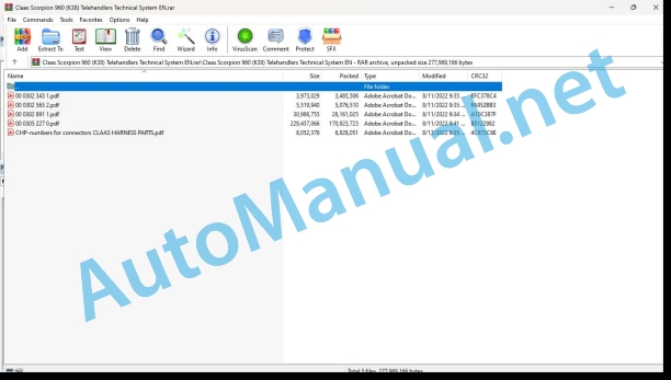
File List:
00 0302 343 1.pdf
00 0302 565 2.pdf
00 0302 891 1.pdf
00 0305 227 0.pdf
CHP-numbers for connectors CLAAS HARNESS PARTS.pdf
00 0302 343 1.pdf:
PROFI CAM 3
Table of contents
General information
Marking of warnings and hazard prevention notes
First-aid measures
CCN explanation
CCN (CLAAS Component Number)
Electric system standard
Overview
Hydraulic system standard
Overview
CCN (CLAAS Component Number)
10 Electrical / Electronic equipment
1030 Board computer / Indicators
Camera system
Description of function
1097 Testing / Measuring / Adjusting
Testing / measuring / adjusting the PROFI CAM
Checking the fuse in the video channel select box (C102)
Testing the video camera connector (C055)
1098 Fault / remedy
Fault / remedy PROFI CAM
The video monitor (C101) shows no image or cannot be switched on (indicator light fails to light up)
Video monitor (C102) displays a blue image either permanently or temporarily
The video monitor image is blurred
Replacing the fuse in the video channel select box (C102)
Connection and connecting cable with video camera (C055)
00 0302 565 2.pdf:
Sensor system
Table of contents
CCN explanation
CCN (CLAAS Component Number)
Electric system standard
Overview
Hydraulic system standard
Overview
CCN (CLAAS Component Number)
Introduction
Safety rules
Safety and hazard information
10 Electrical / Electronic equipment
1097 Testing / Measuring / Adjusting
Test report of the angle sensor (0011780.x)
Application of test report
Required tools
Test report of the angle sensor (0011780.x)
Testing / Measuring / Adjusting of angle sensor (0011780.x)
1. Reason for test
2. Mechanical test of angle sensor
3. Electric test with CDS
4. Electric test with multimeter
5. Mechanical test of connecting cable
Completing the machine
Test report of position and speed sensors
Application of test report
Required tools
Sensor variants
Part numbers of speed sensors
Part number of position sensor
Test report of position and speed sensors
Testing / measuring / adjusting of position and speed sensors
1. Reason for test
2. Mechanical test
3. Electric test with CDS
4a. Installation dimensions
Check of installation dimension
Installation dimensions of gearbox speed sensor (0011 799.x) and cam speed sensor (0011 810.x)
Installation dimension of position sensor (0011 815.x)
4b. Installation position
Centring of sensor
Metal-free zone
5. Electric test with multimeter
Voltage measurement
Direction of rotation and speed sensor (0011 605.x)
Measured values table
6. Mechanical test of connecting cable
Completing the machine
Test report of the urea sensor (00 0773 207 x)
Application of test report
Required tools
Parts number of the urea sensor
Test report of the urea sensor
Testing / measuring / adjusting urea sensor
1. Reason for test
2. Mechanical test
3. Mechanical test of connecting cable
4. Electric test with multimeter
5. Component test with the CDS
00 0302 891 1.pdf:
SCORPION 960 VARIPOWER (K38)SCORPION 756 VARIPOWER (K37)SCORPION 746 VARIPOWER (K35)
Table of contents
Introduction
Validity of Technical Systems documentation
About this Technical Systems documentation
Symbols and notes
Further useful information
General information
Safety precautions
Technical Systems documentation and other sources of information
Importance of Technical Systems documentation
Personnel qualification and organization
Requirements made on all persons working with the machine
Alterations on the machine
Structural alterations
Additional equipment and spare parts
Requirements made on spare parts
Workplace
Control of machine while running
Technically flawless condition
Technically flawless condition of machine
Danger from damage to the machine
Respecting technical limit values
Hazard areas of the machine
Hazard areas
Hitching of machine to implement or trailer
Standing between machine and trailer
Hazard from engaged drive
Danger from machine parts that continue rotating
Safety devices
Keeping safety devices functional
Personal protective equipment
Personal protective equipment
Wearing suitable clothing
Safety markings
Keeping safety decals legible
Road safety
Hazards when driving on the road and on the field
Stability hazard
Preparing the machine for road travel
Parking the machine safely
Unsupervised parking
Keeping the machine free of foreign objects
Operating utilities
Unsuitable operating utilities
Safe handling of operating and auxiliary utilities
Fuel is detrimental to your health
Refrigerant is detrimental to your health
Environmental protection and disposal
Chemicals
Keeping the cab free of chemicals
Hazards from the work environment
Fire hazard
Potentially fatal electric shock from overhead lines
Behaviour in case of voltage flash-over due to overhead lines and when lightning strikes
Sources of hazards on the machine
Electric shock from electric system
Noise may damage your health
Vibrations may damage your health
Liquids under pressure
Compressed air
Toxic exhaust gases
Hot surfaces
Hazards when accessing and getting off the machine
Safe access and getting off
Hazards when working on the machine
Work only on the machine after shutting it down
Inspection, adjusting, maintenance and repair work
Raised machine parts and loads
Danger from welding work
Danger from painting work
Work on the electric system
Work on the diesel engine
Handling fuels
Handling hot liquids
Marking of warnings and hazard prevention notes
Safety routines
First-aid measures
Jacking up the machine
Jacking up the machine for preparing the ground drive test protocol
Jacking-up of machine for calibrating the DMS evaluation unit without a crane
CCN explanation
CCN (CLAAS Component Number)
CCN (CLAAS Component Number)
LCN (LIEBHERR Component Number)
CLAAS electric systems standard
Overview
CN standard of LIEBHERR Werke Telfs
Designations of electronic components (CN standard) of LIEBHERR Werke Telfs
Designations of hydraulic and mechanical components
CCN (CLAAS Component Number)
01 Engine
0135 Cooling system
Cooling system – type K35
Hydraulic system overview
Description of function
Layout of combined radiator
Cooling system – type K37/K38
Hydraulic system overview
Description of function
Layout of combined radiator
Reversing fan – type K35
Overview of hydraulic system
Description of function
Reversing fan – type K37/K38
Overview of hydraulic system
Description of function
0150 Engine attachment parts
Starting the diesel engine
0155 Engine control
Diesel engine monitoring
0197 Test/Measurement/Setting
Testing and measuring the fan drive – type K35/K37/K38
Important notes regarding the test protocol
Required tools and screw fittings
Preparation for creating the test protocol
Test and adjusting protocol
Preparation for hydraulic testing
Execution
Fan drive pressure limitation
Example measurement, fan drive
03 Chassis
0305 Axle suspension
Level compensation – model K38
Function description of level compensation
Swi axle lock – type K38
Function description of rear axle swing lock
Operating function
0335 Ground drive
Ground drive – type K35
Functional description of ground drive
Control of axial piston variable-displacement pump
Control of variable-displacement motor
Ground drive – type K37/K38
Functional description of ground drive
Control of axial piston variable-displacement pump
Control of variable-displacement motor and of additional variable-displacement motor
0397 Testing / measuring / adjusting
Testing and measuring the ground drive – type K35/K37/K38
Important notes regarding the test protocol
Application of test protocol
Required tools and screw fittings
Preparation for creating the test protocol
Test and adjusting protocol
Preparation for hydraulic testing
Test of tyres
Testing with standard measuring units
Operating temperature
Execution – variable-displacement pump charge pressure
Checking the variable-displacement pump charge pressure
Measured values table
Charge pressure
Example measurement, charge pressure
Execution – hydraulic zero position
Check the variable-displacement pump hydraulic zero position.
Hydraulic test
Hydraulic zero position
Example measurement, hydraulic zero position
Execution – Checking the high-pressure limitation
Check the high pressure
Pre-check with CDS
Pressure limitation of high pressure
Example measurement, forward high-pressure test
Example measurement, reverse high-pressure test
Checking with blinding the high-pressure circuit
04 Brake
0405 Service brake
Service brake
Brake hydraulics overview
Description of function
0415 Parking brake
Parking brake
Key to diagram
Brake hydraulics overview
Description of function
0420 Trailer air brake
Compressed-air trailer brake system
Description of function
Description of function
0425 Trailer hydraulic brake
Hydraulic trailer brake, double line
Description of function
0497 Testing / measuring / adjusting
Testing and measuring the brake system
Important notes regarding the test protocol
Required tools and screw fittings
Preparation for creating the test protocol
Test and adjusting protocol
Preparation for hydraulic testing
Execution – brake pressure of parking brake
Checking the brake hydraulics pilot pressure
Check the brake pressure of the parking brake
Measured values table
Brake pressure of parking brake – applied
Execution – brake pressure of service brake
Checking the brake pressure of service brake
Measured values table
Brake pressure of service b
05 Steering
0505 Steering
Steering system
Functional description of steering system
Steering hydraulics neutral function
Steering cylinder
Steering operation
0597 Tng / measuring / adjusting
Testing and measuring the steering system
Important notes regarding the test protocol
Required tools and screw fittings
Preparation for creating the test protocol
Test and adjusting protocol
Preparation for hydraulic testing
Execution – checking the steering cylinder control pressure
Pre-check with CDS
Measured values table
Control pressure of steering cylinders
06 Lift device
0620 Telescopic arm
Raising / lowering the telescopic arm
Functional description of Raising / lowering the telescopic arm
Pilot controller
Variable-capacity pump to proportional control block
Proportional control block
Lifting cylinder and compensating cylinder
Raising the telescopic arm
Lowering the telescopic arm
Retracting / extending the telescopic arm
Telescoping cylinder
Functional description of Extending the telescopic arm
Functional description of Retracting the telescopic arm
Tipping the quick-hitch plate in / out
Neutral function of working hydraulics
Tipping cylinder
Functional description of Tipping the quick-hitch plate in / out
Tipping the quick-hitch plate in
Tipping the quick-hitch plate out
Pitching dampening
Overview of pitching dampening hydraulic system
Description of function
Lifting unit suspension active
Automatic lifting unit suspension
Lifting unit suspension deactivated
0697 Testing / measuring / adjusting
Calibrating the DMS evaluation electronics – type K35/K37/K38
0698 Problems / remedy
Troubleshooting by lighting up LEDs on the DMS evaluation electronics unit
07 Hitch
0720 Hitch
Trailer hitch
Overview of hydraulic system
Function description of Unlocking the trailer hitch
Function description of Lowering the trailer hitch
Function description of Lifting and locking the trailer hitch
09 Hydraulic system
0905 Hydraulic oil tank
Hydraulic oil tank
Connections
0910 Pumps
Axial-piston variable-displacement pump (ground drive hydraulics)
Variable-capacity pump (working hydraulics)
Gear pump (charge pump)
0915 Hydraulic lines
Hydraulic filter
Charge pressure filter
Connections
Screen filter
0920 Valves
Proportional control block
Priority valve
Parking brake valve block
Inching pedal
Rear axle adjustment valve
Steering type control directional control valve
Steering unit
Blocking block
Fan proportional valve
Load retaining valve (121-LWT)
Lower brake valve (112-LWT)
Lower brake valve (126-LWT)
Lower brake valve (131-LWT)
Trailer brake valve (200-LWT)
0940 Power hydraulics
3rd control circuit
Functional description of connection A on 3rd control circuit
Function description of pressure relief, 3rd control circuit
Electric change-over of 3rd control circuit
Hydraulic system overview
Description of function
4th control circuit with tipper connection
Overview of hydraulic system
Functional description of Raise tipper
Functional description of Lower tipper
4th control circuit with tipper hydraulics and rear hydraulics
Overview of hydraulic system
Functional description of Actuation of 4th control circuit to connection A with rear hydraulics
Functional description of Actuation of 4th control circuit to connection B with rear hydraulics
Functional description of Raise tipper
Functional description of Lower tipper
SCORPION quick-hitch plate
Overview of hydraulic system
Description of function
Hitching and locking the working attachment
0980 Hydraulic circuit diagram
Circuit diagrams – model K35
Entire hydraulic system
Ground drive hydraucs
Steering hydraulics
Brake hydraulics
Cooling system
Reversing fan
Working hydraulics
Quick-hitch plate
Lifting unit suspension
Tipper and ar hydraulics
Tipper connection
3rd control circuit
High Flow, 3rd control circuit leakage oil line
3rd control circuit change-over
Trailer brake
Circuit diagrams – type K37/K38
Overall hydraulic system – type K37
Overall hydraulic system – type K38
Ground drive hydraulics
Steering hydraulics
Brake hydraulics
Cooling system
Reversing fan
Working hydraulics
Quick-hitch plate
Lifting unit suspension
Tipper and rear hydraulics
Tipper connection
3rd control circuit
High Flow, 3rd control circuit leakage oil line
3rd control circuit change-over
Trailer brake
0997 Testing / measuring / adjusting
Testing and measuring the working hydraulics
Important notes regarding the test protocol
Test and adjusting protocol
Preparation for hydraulic testing
Testing with standard measuring units
Operating temperature
Working hydraulics differential pressure
Working hydraulics standby pressure
Working hydraulics pilot pressure
Load-sensing pressure cut-off
Secondary safeguard pressure relief valves – lifting, lowering, tipping in, tipping out
Secondary safeguard pressure relief valves – retracting the telescopic arm, extending the telescopic arm, 3rd control circuit (A), 3rd control circuit (B)
Checking the lower brake valve/pipe break safeguard with the hand pump
10 Electrical / Electronic equipment
1005 Power supply
Function of electric battery isolating switch
Function description of electronic battery isolating switch
1010 Central electrics
Cab central electrical system
Fuse assignment of the central electrical system (cab)
Fuse box in engine compartment – type K35
Devices installed – fuse box in engine compartment
Fuse box in engine compartment – type K37 / K38
Devices installed – fuse box in engine compartment
1012 Modules / sensors
Module A1-LWT – Ground drive hydraulics control box
Key to diagram
Connection without component designation
Module A4-LWT – DMS evaluation electronics
Key to diagram
Connection without component designation
Module A30-LWT – Working hydraulics control box (1/2)
Key to diagram
Connection without component designation
Module A30-LWT – Working hydraulics control box (2/2)
Key to diagram
Connection without component designation
Module A33-LWT – Display
Key to diagram
Connection without component designation
Module A35-LWT – LED display
Key to diagram
Connection without component designation
Module A36-LWT – Diesel engine electronics (1/4) – type K35
Key to diagram
Connection without component designation
Module A36-LWT – Diesel engine electronics (2/4) – type K35
Key to diagram
Connection without component designation
Module A36-LWT – Diesel engine electronics (3/4) – type K35
Key to diagram
Connection without component designation
Module A36-LWT – Diesel engine electronics (4/4) – type K35
Key to diagram
Module A36-LWT – Diesel engine electronics (1/4) – type K37/K38
Key to diagram
Connection without component designation
Module A36-LWT – Diesel engine electronics (2/4) – type K37/K38
Key to diagram
Connection without component designation
Module A36-LWT – Diesel engine electronics (3/4) – type K37/K38
Key to diagram
Module A36-LWT – Diesel engine electronics (4/4) – type K37/K38
Key to diagram
Module A38-LWT – Engine electronics – type K35
Key to diagram
Connection without component designation
Module A38-LWT – Engine electronics – type K37/K38
Key to diagram
Module A39-LWT – Joystick
Key to diagram
Connection without component designation
Module A40-LWT – Control unit option package 1
Key to diagram
Connection without component designation
Module A47-LWT – Display TERA 7
Key to diagram
Connection without component designation
Module A50-LWT – Control unit option package 2 (1/2)
Key to diagram
Connection without component designation
Module A50-LWT – Control unit option package 2 (2/2)
Key to diagram
Connection without component designation
1035 Operation / Multifunction control lever
Operating lever – type
1080 Electrical circuit diagram
Electric circuit diagrams (SCM) Wire colours and layout of lines
Introduction to electric system circuit diagrams (SCM) Marking information
Electric system circuit diagrams (SCM) Basic machine
SCM 03 / Main fuse, power supply, automatic battery isolating switch and ignition start switch
Key to diagram
Connectors
SCM 04 / Splice and earth terminals
Key to diagram
Connectors
SCM 05 / Search light switch
Key to diagram
Connectors
SCM 06 / Emergency OFF, exhaust system stage 4: Regeneration, EAT bridging, engine wiring loom interface
Key to diagram
Connectors
SCM 08 / Torque limitation, working pump swivel angle sensor, working hydraulics OFF, working hydraulics supply
Key to diagram
Modules, plug-in connections
SCM 09 / Overload – Warning device, retarder
Key to diagram
Modules, plug-in connections
SCM 10 / Control block actuation
Key to diagram
Modules, plug-in connections
SCM 11 / Lift angle sensor, fan control, hydraulic oil temperature sensor
Key to diagram
Modules, plug-in connections
SCM 13 / Ground drive hydraulics supply, pump, hydrostatic motor control, brake light, trailer brake
Key to diagram
Modules, plug-in connections
SCM 14 / Axles proximity switch, electric steering types – adjustment
Key to diagram
Modules, plug-in connections
SCM 15 / Steering types valve control, level compensation
Key to diagram
Modules, plug-in connections
SCM 16 / Ground drive hydraulics, pedals’ angle sensor, hand inch
Key to diagram
Modules, plug-in connections
SCM 17 / Parking brake switch, parking brake valve, pressure sensor (B69-LWT, B12-LWT), speed sensor, compressor seat, engine start seat contact switch
Key to diagram
Connectors
SCM 18 / Joystick
Key to diagram
Connectors
SCM 19.1 / Display, tank sensor, return line filter pressure switch
Key to diagram
Connectors
SCM 19.2 / Display, TERA 7
Key to diagram
Connectors
SCM 21 / LED symbol display
Key to diagram
Connectors
SCM 22 / Fan step switch, fan motor, air conditioner
Key to diagram
Connectors
SCM 23 / Windscreen front window / rear window / side window wiper/washer system, horn, steering column switch
Key to diagram
Connectors
SCM 24 / Light switch, main beam, dipped beam, contour lights, turn indicator, cab light, door pillar switch
Key to diagram
Connectors
SCM 25 / Exhaust system stage 4: Power supply, feed module, heater
Key to diagram
Connectors
SCM 26 / Exhaust system stage 4: Urea sensors, ambient temperature sensor
Key to diagram
Connectors
SCM 27 / Back-up horn, steering column switch, taillight, brake light, rear number plate lighting, hazard warning flasher, back-up light
Key to diagram
Connectors
SCM 28 / Cab sockets, boom socket, rear and side window heater
Key to diagram
Connectors
SCM 29 / Front and rear work lights
Key to diagram
Connectors
SCM 30 / Telescopic arm and side work light, trailer preparation
Key to diagram
Connectors
SCM 31 / Broadcast radio, immobilizer preparation, camera system preparation, rear number plate lighting, warning beacon
Key to diagram
Connectors
SCM 32 / Oil level sensor, central lubrication system, compressed air system, Lidat / Telematics preparation, quick-hitch plate preparation
Key to diagram
Connectors
SCM 33 / Communication I
Key to diagram
Connectors
SCM 34 / Communication II
Key to diagram
Connectors
SCM 35 / Communication III: Working hydraulics control
Key to diagram
Connectors
SCM 37 / Working hydraulics supply II, differential lock, lifting unit suspension
Key to diagram
Modules, plug-in connections
SCM 38 / Swing axle lock, tipping cylinder lock, hand throttle
Key to diagram
Connectors
SCM 39 / Tipping angle sensor, 4-wheel drive shut-down, auto throttle
Key to diagram
Modules, plug-in connections
SCM 40 / Swing axle lock, lifting unit suspension, 4-wheel drive shut-down, additional hydraulic motor, differential lock
Key to diagram
Modules, plug-in connections
SCM 41 / Spare interface connector
Connectors
SCM 42 / Spare main board
Key to diagram
Connectors
Diesel engine TCD 3.6 (Stage V) electric system circuit diagrams (SCM)
SCM 03 / Engine control unit and engine sensors
Key to diagram
Connectors
SCM 04 / Exhaust system sensors
Key to diagram
Modules, connectors, earth terminals
SCM 05 / Exhaust system relay
Key to diagram
Modules, connectors, earth terminals
SCM 06 / Interface of engine – basic device, power supply and fuel pump
Key to diagram
Modules, connectors, earth terminals
SCM 07 / Pressure switch and air conditioner
Key to diagram
Connectors, earth points
Diesel engine TCD 3.6 (Stage TIER 4f) electric system circuit diagrams (SCM)
SCM 03 / Engine control unit and engine sensors
Key to diagram
Connectors
SCM 04 / Exhaust system sensors
Key to diagram
Modules, plug-in connections
SCM 05 / Exhaust system relay
Key to diagram
Modules, plug-in connections
SCM 06 / Engine interface – basic device, electronics power supply and coolant level sensor
Key to diagram
Modules, plug-in connections
SCM 07 / Pressure switch and air conditioner
Key to diagram
Connectors, earth points
Diesel engine TCD 3.6 (Stage TIER 3a) electric system circuit diagrams (SCM)
SCM 03 / Engine control unit and engine sensors
Key to diagram
Connectors
SCM 04 / Interface of engine – basic device, power supply and fuel pump
Key to diagram
Modules, connectors, earth terminals
SCM 05 / Pressure switch and air conditioner
Key to diagram
Connectors, earth points
Diesel engine TCD 4.1 (Stage V) electric system circuit diagrams (SCM)
SCM 03 / Engine control unit and engine sensors
Key to diagram
Connectors
SCM 04 / Exhaust system sensors
Key to diagram
Modules, plug-in connections
SCM 05 / Exhaust system relay
Key to diagram
Modules, plug-in connections
SCM 06 / Engine interface – basic device, electronics power supply and coolant level sensor
Key to diagram
Modules, connectors, earth terminals
SCM 07 / Pressure switch and air conditioner
Key to diagram
Connectors
Diesel engine TCD 4.1 (Stage TIER 4f) electric system circuit diagrams (SCM)
SCM 03 / Engine control unit and engine sensors
Key to diagram
Connectors
SCM 04 / Exhaust system sensors
Key to diagram
Modules, plug-in connections
SCM 05 / Exhaust system relay
Key to diagram
Modules, plug-in connections
SCM 06 / Engine interface – basic device, electronics power supply and coolant level sensor
Key to diagram
Modules, connectors, earth terminals
SCM 07 / Pressure switch and air conditioner
Key to diagram
Connectors
Diesel engine TCD 4.1 (Stage TIER 3a) electric system circuit diagrams (SCM)
SCM 03 / Engine control unit and engine sensors
Key to diagram
Connectors
SCM 04 / Interface of engine – basic device, power supply and fuel pump
Key to diagram
Modules, connectors, earth terminals
SCM 05 / Pressure switch and air conditioner
Key to diagram
Connectors, earth points
Electric system circuit diagrams (SCM) Arm wiring loom
SCM 02 Arm
Key to diagram
Modules, connectors, earth terminals
Electric circuit diagrams (SCM) option package
SCM 04 / Control unit supply, search light, quick-hitch plate, control circuit 3
Key to diagram
Connectors
SCM 05 / Reversing fan, trailer brake, control circuit 3 valves, telescopic boom interface
Key to diagram
Modules, plug-in connections
SCM 06 / Working hydraulics fine control, control circuit 4, control circuit 5,
Key to diagram
Modules, plug-in connections
SCM 07 / Automatic trailer hitch sensor, control circuit 4 and control circuit 5 valves
Key to diagram
Modules, plug-in connections
SCM 08 / Control circuit 4 / 5, communication I, communication III actuator
Key to diagram
Connectors
TELEMATICS electric system circuit diagrams (SCM)
SCM 03 / TELEMATICS
Key to diagram
Connectors
Electric system circuit diagrams (SCM) Trailer brake system
SCM 02 / Trailer brake system
Key to diagram
Connectors
Electric system circuit diagrams (SCM) Fuel pre-heater
SCM 03 / Fuel pre-heater
Key to diagram
Connectors
Electric system circuit diagrams (SCM) Immobilizer
SCM 03 / Immobiliser
Key to diagram
Connectors
1081 Overview of connectors
Connector overview
Overall overview
Cab connector
Telescopic arm connector
Telescopic arm connector
Diesel engine connector – type K37 / K38
Diesel engine TIER 3a connector- type K35
Diesel engine exhaust stage V / TIER 4f connector – type K35
Option package 2 connector
1085 Networks
CAN Bus network – type K35
Overview of CAN Bus networks – type K35
Description of function
CAN Bus network – type K37/K38
Overview of CAN Bus networks – type K37/K38
Description of function
12 Cab / Operator’s platform
1240 Air condition
Air conditioner
Description of function
Air conditioner
Refrigerant circuit
75 Central lubrication system
7515 Lubrication system / Lines
Central lubrication system
Electric pump EP-1 principle
Control and operation of central lubricating pump
Function sequence
Manual intermediate lubrication
Signalling
Progressive distributor MX-F
Explanation
Description of function
7597 Testing / measuring / adjusting
Adjusting – Central lubrication system
Setting of parameters
Setting the operating pressure
92 Diagnosis
9210 Error codes machine
FMI fault codes
FMI 00 (signal too high)
FMI 01 (signal too low)
FMI 02 (erratic signal)
FMI 03 (voltage too high)
FMI 04 (voltage too low)
FMI 05 (current too low)
FMI 06 (current too high)
FMI 07 (mechanical fault)
FMI 08 (faulty frequency signal)
FMI 09 (communication fault)
FMI 10 (signal change too fast)
FMI 11 (multiple faults)
FMI 12 (ECU defective)
FMI 13 (signal outside of calibration range)
FMI 16 (parameter not available)
FMI 17 (ECU does not respond)
FMI 18 (power supply fault)
FMI 19 (software conditions not met)
FMI 95 (no signal change)
FMI 96 (CAN BUS system defective)
FMI 97 (erratic status)
FMI 98 (warning)
FMI 99 (Info)
Fault code list of machine
Position of components
Hydraulic system
Hydraulic components
Electric system
A Modules, electronic components
B Sensors, signal transducers
E Lighting
G Voltage sources
H Indicator lights
M Motor (electric)
R Potentiometer/resistor
S Switch / pushbutton
T Antennas
U Pushbutton – external operation
X Connectors
Y Solenoid coil
Earth points
00 0305 227 0.pdf:
SCORPION 960 VARIPOWER (K38)SCORPION 756 VARIPOWER (K37)SCORPION 746 VARIPOWER (K35)
Table of contents
Introduction
Validity of Technical Systems documentation
About this Technical Systems documentation
Symbols and notes
Further useful inf
John Deere Parts Catalog PDF
John Deere Tractors 6300, 6500, and 6600 Parts Catalog CQ26564 (29SET05) Portuguese
John Deere Parts Catalog PDF
John Deere Tractors 7500 Parts Catalog CPCQ26568 30 Jan 02 Portuguese
John Deere Repair Technical Manual PDF
John Deere Repair Technical Manual PDF
John Deere Repair Technical Manual PDF
John Deere Repair Technical Manual PDF
John Deere Repair Technical Manual PDF
John Deere Application List Component Technical Manual CTM106819 24AUG20
John Deere Parts Catalog PDF
John Deere Harvesters 8500 and 8700 Parts Catalog CPCQ24910 Spanish
John Deere Repair Technical Manual PDF
John Deere DF Series 150 and 250 Transmissions (ANALOG) Component Technical Manual CTM147 05JUN98
New Holland Service Manual PDF

