Claas Talos 240-210 (A39) Tractors Operator Manual EN
$50.00
- Model: Talos 240-210 (A39) Tractors
- Type Of Manual: Operator Manual
- Language: EN
- Format: PDF(s)
- Size: 91.0 MB
File List:
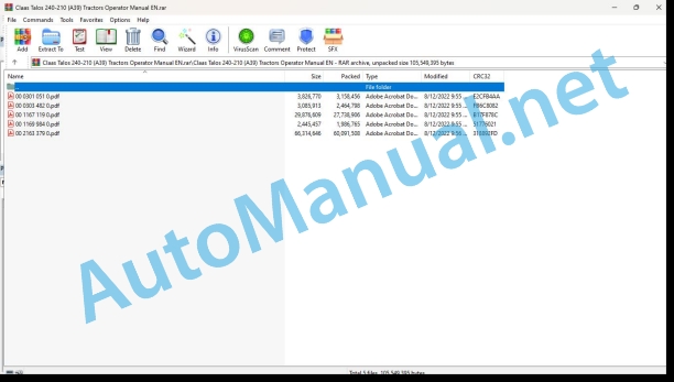
00 0301 051 0.pdf
00 0303 482 0.pdf
00 1167 119 0.pdf
00 1169 984 0.pdf
00 2163 379 0.pdf
00 0301 051 0.pdf:
PROFI CAM 3
Table of contents
1 Introduction
1.1 Notes on the manual
1.1.1 Validity of manual
1.1.2 Information about this Operator’s Manual
1.1.3 Symbols and notes
1.1.4 Optional equipment
1.1.5 Qualified specialist workshop
1.1.6 Maintenance information
1.1.7 Warranty notes
1.1.8 Spare parts and technical questions
1.2 Intended use
1.2.1 Intended use
1.2.2 Reasonably foreseeable misuse
2 Safety
2.1 Identifying warnings
2.1.1 Hazard signs
2.1.2 Signal word
2.2 Safety rules
2.2.1 Meaning of Operator’s Manual
2.2.2 Observing safety decals and warnings
2.2.3 Optional equipment and spare parts
3 Product description
3.1 Overview and method of operation
3.1.1 How the PROFI CAM works
3.2 Identification plates and identification number
3.2.1 Position of identification plates
3.2.2 Explanation of PROFI CAM identification plate
3.3 Information on the product
3.3.1 CE marking
4 Operating and control elements
4.1 Camera system
4.1.1 Camera system monitor
4.2 Menu structure
4.2.1 Main menu
4.2.2
4.2.3
4.2.4
4.2.5
4.2.6
5 Technical specifications
5.1 PROFI CAM
5.1.1 Monitor
5.1.2 Camera
5.1.3 Switch box
5.1.4 Degree of protection against foreign bodies and water
6 Preparing the product
6.1 Shutting down and securing the machine
6.1.1 Switching off and securing the machine
6.2 Prior to operation
6.2.1 Carry out prior to operation
6.2.2 Installing the sun protection
6.2.3 Aligning the camera
6.2.4 Connecting the camera electrics
7 Operation
7.1 Monitor
7.1.1 Switching on the monitor
7.1.2 Calling up the menu
7.1.3 Setting a menu item
7.1.4 Setting the image orientation
7.1.5 Setting automatic screen darkening
7.1.6 Image mirroring
7.1.7 Setting the trigger view
7.1.8 Setting the follow-up time for trigger view
7.1.9 Setting the display mode
7.1.10 Activating/deactivating a display mode
8 Faults and remedies
8.1 Electrical and electronic system
8.1.1 Overview of problems on PROFI CAM camera system
8.1.2 Replacing the switch box fuse
9 Maintenance
9.1 Maintenance intervals
9.1.1 Every 10 operating hours or daily
9.2 Camera system
9.2.1 Checking the camera system for dirt
9.2.2 Cleaning the camera
9.2.3 Cleaning the switch box
9.2.4 Cleaning the monitor
10 Placing out of operation and disposal
10.1 General Information
10.1.1 Putting out of operation and disposal
11 Technical terms and abbreviations
11.1 Abbreviations
11.1.1 Units
11.1.2 Abbreviations
11.1.3 Technical terms
00 0303 482 0.pdf:
PROFI CAM 4
Table of contents
1 Introduction
1.1 Notes on the manual
1.1.1 Validity of manual
1.1.2 Information about this Operator’s Manual
1.1.3 Symbols and notes
1.1.4 Optional equipment
1.1.5 Qualified specialist workshop
1.1.6 Maintenance information
1.1.7 Notes on warranty
1.1.8 Spare parts and technical questions
1.2 Intended use
1.2.1 Intended use
1.2.2 Reasonably foreseeable misuse
2 Safety
2.1 Identifying warnings
2.1.1 Hazard signs
2.1.2 Signal word
2.2 Safety rules
2.2.1 Meaning of Operator’s Manual
2.2.2 Structural changes
2.2.3 Optional equipment and spare parts
2.2.4 Operation only following proper putting into operation
2.2.5 Technical status
2.2.6 Respecting technical limit values
Respecting technical limit values
2.2.7 Hazards when driving on roads and fields
3 Product description
3.1 Overview and method of operation
3.1.1 How the PROFI CAM works
3.2 Identification plates and identification number
3.2.1 Identification plates
3.3 Information on the product
3.3.1 CE marking
4 Operating and display elements
4.1 Camera system
4.1.1 Camera system monitor
4.1.2 CEBIS
4.2 Menu structure
4.2.1 Main menu
4.2.2
4.2.3
4.2.4
4.2.5
4.2.6
5 Technical specifications
5.1 PROFI CAM
5.1.1 Monitor
5.1.2 Camera
5.1.3 Switch box
6 Preparing the product
6.1 Switching off and securing the machine
6.1.1 Switching off and securing the machine
6.2 Prior to putting into operation
6.2.1 Carry out prior to operation
6.2.2 Installing the sun protection
6.2.3 Aligning the camera
7 Operation
7.1 Monitor
7.1.1 Switching on the monitor
7.1.2 Calling up the menu
7.1.3 Setting a menu item
7.1.4 Setting the image orientation
7.1.5 Setting automatic screen darkening
7.1.6 Image mirroring
7.1.7 Setting the trigger view
7.1.8 Setting the follow-up time for trigger view
7.1.9 Setting the display mode
7.1.10 Activating/deactivating a display mode
8 Faults and remedies
8.1 Electric and electronic system
8.1.1 Overview of problems on PROFI CAM camera system
9 Maintenance
9.1 Maintenance intervals
9.1.1 Every 10 operating hours or daily
9.2 Camera system
9.2.1 Checking the camera system for dirt
9.2.2 Cleaning the camera
9.2.3 Cleaning the switch box
9.2.4 Cleaning the monitor
10 Putting out of operation and disposal
10.1 General information
10.1.1 Putting out of operation and disposal
11 Technical terms and abbreviations
11.1 Abbreviations
11.1.1 Units
11.1.2 Abbreviations
11.1.3 Technical terms
00 1167 119 0.pdf:
TALOS 240-230-220-210
Table of contents
1 To this Operator’s Manual
1.1 Notes on the manual
1.1.1 Using the operator’s manual
Important information concerning this operator’s manual
Structure based on tractor sub-assemblies
Search and find
Direction indications
Specific terminology
Optional and additional equipment
1.1.2 Symbols and instructions
Text and illustrations
Highlighting dangers and warnings
1.1.3 Validity of the operator’s manual
1.1.4 Technical information
2 Safety
2.1 Safety rules
2.1.1 Appropriate use
2.1.2 Inappropriate use
2.1.3 Safety and accident prevention instructions
2.1.4 Driving the tractor
2.1.5 Checking the condition of the tractor
2.1.6 Climbing into and out of the tractor
Climbing into the tractor
Climbing out of the tractor
2.1.7 Passengers
2.1.8 Cab
Safety structure of the cab
Polluted environment
2.1.9 Precautions to be taken before starting up
2.1.10 Adjustments and maintenance work
Special notes on mounting the tractor on axle stands
2.1.11 Hitching implements
2.1.12 Using the front/rear power take-off
2.1.13 Fuel
2.1.14 Engine coolant
2.1.15 Air conditioning
2.1.16 Electrical system
2.1.17 Electromagnetic compatibility (EMC)
2.1.18 Applications with front loaders
2.1.19 Forest applications
2.1.20 Working in a fixed position
2.1.21 Implements operating at great depth
2.2 Safety decals on the tractor
2.2.1 General advice regarding the safety markings
2.2.2 Warning symbols
2.3 Safety devices
2.3.1 Cover
2.3.2 Wings
2.3.3 Power take-off guard and protective sleeve
3 Tractor description
3.1 Overview
3.1.1 Description
Cab version
Platform version
3.2 Identification plates and vehicle identification number
3.2.1 Identification plates
Tractor identification plate
Engine identification plate
Carraro front axle identification plate
4 Operating and display elements
4.1 Cab and operator’s platform
4.1.1 Control and display symbols
4.1.2 Dashboard
Left-hand side
Right-hand side
4.1.3 Left-hand console and controls on the seat support
4.1.4 Right-hand console
4.1.5 Cab pillar
Right-hand side
4.1.6 Multifunction armrest (electro-hydraulic lifting, depending on equipment)
4.1.7 Instrument panel
4.1.8 Ventilation and air conditioning
4.1.9 Control lever for indicator lights and audible warning
Switching the signal lights on/off
Switching the main beam lights on/off
Indicator control
4.1.10 Work light controls
Cab version
Platform version
4.1.11 Warning beacon (option)
4.1.12 Hazard warning lights control
4.1.13 Wiper/washer (cab version)
4.1.14 Electrical socket (cab version)
4.2 Electric and electronic system
4.2.1 Rear linkage external controls
4.2.2 Electric trailer socket (option)
5 Technical specifications
5.1 TALOS 240 – 210
5.1.1 Dimensions
TALOS 210 and TALOS 220
TALOS 230
TALOS 240
5.1.2 Weight
5.1.3 Engine
5.1.4 Transmission
5.1.5 Ground speeds
5.1.6 Front axle
5.1.7 Rear axle
5.1.8 Direction
5.1.9 Lifting
5.1.10 Hitches
5.1.11 Maximum authorised tow weights
5.1.12 Load capacities
5.1.13 Power take-off
5.1.14 Hydraulic system
5.1.15 Electrical system
Electric trailer socket wiring
Version CE
Version ASAE
5.1.16 Cab
Seat vibration level
5.1.17 Air conditioning
5.1.18 Lubricants/Hydraulic oil
Using engine oil
5.1.19 Engine coolant
5.1.20 Air conditioning refrigerant
6 Tractor preparation
6.1 Engine
6.1.1 Fuel
Quality requirement
Using cold start fuel
Fuel storage
Precautions to be taken when handling fuel
6.1.2 Topping up
6.1.3 Checks before starting the engine
6.2 Frame
6.2.1 Front tracks
Front disc and rim configuration
Adjusting the steering stops
6.2.2 Rear tracks
Rear disc and rim configuration
Gap check
6.2.3 Tyres
6.2.4 Tyre load capacity and inflation pressure
6.3 Brake
6.3.1 Coupling the brake pedals
6.4 Steering
6.4.1 Steering column
6.5 Rear power lift
6.5.1 Axle stands
6.5.2 Upper connecting rod
6.5.3 Hitching and unhitching an implement
Recommendations
Hitching an implement
Transport
Storing the 3-point hitch
6.6 Front loader
6.6.1 Front loader mounting points
6.6.2 Hydraulic valves
6.7 Rear power take-off
6.7.1 Power take-off connection
6.8 Hitch
6.8.1 Hitch types
Recommendations
Jaw drawbar
Swinging jaw drawbar
6.9 Cab and operator’s platform
6.9.1 Folding roll hoop (ROPS)
6.9.2 Adjusting the seat
6.9.3 Seat belt
6.9.4 Checks before starting
6.9.5 Setting the clock
6.10 Assembly parts and bodywork
6.10.1 Opening and closing the bonnet
6.10.2 Balancing the tractor with mounted implements
Summary table
6.10.3 Fitting and removing the front weights
6.10.4 Rear wheel weights
45 kg wheel weights
6.11 Transport of the tractor
6.11.1 Transport
7 Operation
7.1 Engine
7.1.1 Recommendations for use
7.1.2 Recommendations concerning the turbocharger
7.1.3 Starting the engine
Preliminary operations
Start the engine
Starting in cold weather
7.1.4 Accelerator pedal
7.1.5 Hand accelerator
7.1.6 Stopping the engine
7.2 Transmission, clutch and driveshaft
7.2.1 Transmission without Power Shuttle System
Direction of travel selection
Gear lever
Range lever
7.2.2 Transmission with Power Shuttle System
Direction of travel selection
Gear lever
Gear selection
Range lever
Engagement mode selection switch
7.2.3 Creeper gear range (depending on equipment)
7.2.4 Differential lock
7.3 Chassis
7.3.1 Front axle engagement
7.4 Brake
7.4.1 Service brakes
Brake pedals
7.4.2 Handbrake
7.4.3 Immobilising the tractor
7.5 Rear power lift
7.5.1 Mechanical lifting
Position control
Draft control
Mixed control
Lowering speed
Linkage automation
7.5.2 Electro-hydraulic power lift
Unlocking the rear linkage
Selecting the work mode
Position control
Bottom stop adjustment button
Draft control
Soil entry control
Upper stop adjustment button
Raising/lowering switch
Lowering speed
Linkage automation
External controls
7.6 Front loader
7.6.1 Front loader controls
7.7 Rear power take-off
7.7.1 Power take-off speed selection
Power take-off speed selector lever
Lever for power take-off proportional to ground speed
7.7.2 Using the cab control
7.8 Rear hydraulic system
7.8.1 Association between the controls and the rear power take-offs
7.9 Cab and operator’s platform
7.9.1 Air conditioning and heating (cab version)
Controls
Activate the air conditioning
Increasing the air pressure in the cab
Adjusting the ventilated air flow
Cab air filters
7.9.2 Interior lighting (cab version)
7.9.3 Audio equipment (cab version)
8 Faults and remedies
8.1 Alarms
8.1.1 Alarms
8.2 Engine
8.2.1 Starting using an external battery
8.2.2 Removing water from the fuel filter
8.3 Chassis
8.3.1 Fitting a jack
8.3.2 Digging out the tractor
Digging out a tractor by towing
8.3.3 Towing the tractor
8.4 Steering
8.4.1 Steering
8.5 Electric and electronic system
8.5.1 Fuses and relays
Main fuse
Checking and replacing fuses
Chassis fuse box
Cab fuse box (cab version)
8.5.2 Check the battery
8.5.3 Connecting and disconnecting the battery
8.5.4 Recharging the battery
9 Maintenance
9.1 Maintenance Information
9.1.1 Personal protective equipment
9.1.2 Stop and secure the tractor
9.1.3 Cleaning and tidying risk areas
9.1.4 Welding advice
9.1.5 Protective devices on the tractor
9.1.6 Engine
Alternator
Engine lubrication
Engine cooling
Engine belts
9.1.7 Wheels and tyres
9.1.8 Braking system
9.1.9 Direction
9.1.10 Implements driven by a power take-off
9.1.11 Air conditioning
9.1.12 Hydraulic circuit
9.1.13 Electrical system
9.1.14 Energy accumulators
9.1.15 Spare parts
9.1.16 Cleaning and protection
9.1.17 Working at height
9.1.18 Handling heavy components
9.1.19 Maintenance operations under the cab
9.1.20 Lifting the front of the tractor
9.2 Lubrication plan
9.2.1 Lubrication points – 50 hrs
“Taesan Machinery” front axle
Carraro front axle
9.3 Service interval overview
9.3.1 Location of parts
9.3.2 Daily
9.3.3 After the first 50 hours
9.3.4 After first 300 hours
9.3.5 Every 50 hours
9.3.6 Every 300 hours
9.3.7 Every 600 hours
9.3.8 Every 6 months
9.3.9 Annually
9.3.10 Every 1,200 hours
9.4 Maintenance engine
9.4.1 Clean the radiator and its grille
9.4.2 Clean the engine air filter
9.4.3 Replace the engine air filter
9.4heck the engine oil level
9.4.5 Change the engine oil
9.4.6 Replace the engine oil filter
9.4.7 Replace the fuel filter
9.4.8 Bleeding air from thel circuit
9.4.9 Check the coolant level
9.4.10 Changing the coolant
Coolant quality
9.4.11 Adjust the valve clearance
9.4.12 Check the tension of the fan belt
9.4.13 Checking the injection pressure
9.4.14 Clean the condenser and the radiator grille
9.4.15 Checking the tension of the accessories belt
9.5 Maintenance operations gearbox
9.5.1 Adjust the clutch pedal clearance
9.5.2 Bleeding air from the clutch circuit
9.6 Maintanance operations chassis
9.6.1 Checking the Taesan machinery front axle oil level
9.6.2 Checking the level of the Carraro front axle differential unit oil
9.6.3 Checking the level of the Carraro front axle final drive oil
9.6.4 Changing the “Taesan Machinery” front axle oil
9.6.5 Changing the Carraro front axle differential casing oil
9.6.6 Changing thont axle final drive oil
9.6.7 Check the front axle alignment
9.6.8 Check the tyre inflation pressure
9.6.9 Lost or loose components
9.6.10 Checking thghtness of the wheel discs on the hubs
9.6.11 Checking the tightness of the wheel discs on the rims
9.7 Maintenance operations brake
9.7.1 Adjust the brake pedal clearances
9.7.2 Check the brake fluid level
9.7.3 Bleeding air from the brake circuit
9.8 Maintenance operations hydraulic
9.8.1 Check the hydraulic circuit
9.8.2 Checking the hydraulic/transmission oil level
9.8.3 Changing the hydraulic/transmission oil
9.8.4 Replacing the hydraulic oil filter
9.8.5 Replacing the Power Shuttle System oil filter (depending on equipment)
9.9 Maintenance electrical / electronics
9.9.1 Check the electrical system
9.9.2 Check the air conditioning controls
9.10 Maintenance Cab / Operator’s platform
9.10.1 Cleaning the cab air filter
9.10.2 Replace the cab air filter
9.10.3 Check the air conditioning sealing
9.10.4 Check the air conditioning compressor
9.11 Storage
9.11.1 Storage instructions
10 Putting out of operation and disposal
10.1 Information on the machine
10.1.1 Scrapping and waste disposal
11 Technical terms and abbreviations
11.1 Technical terms and abbreviations
11.1.1 Technical terms and abbreviations
11.1.2 Units of measurement and abbreviations
00 1169 984 0.pdf:
Sensor case for tractors Stage IIIB, IV and VSensor case for tractors Stage IIIB, IV and VSensor case for Stage IIIB, IV and V tractors
Contents
1 Sensorkoffer – Sensor case – Sensor suitcase – Stage IIIB, IV & V
1.1 Auflistung Kofferinhalt
1.1 Listing case content
1.1 Presentation of the contents of the suitcase
00 2163 379 0.pdf:
TALOS 240-230-220-210
Table of contents
1 To this operator’s manual
1.1 Notes on the manual
1.1.1 Using the user manual
Important information concerning this user manual
Classification per module
Search and find
Direction indications
Special terminology
Optional and additional equipment
1.1.2 Symbols and instructions
Text and illustrations
Highlighting dangers and warnings
1.1.3 Validity of the user manual
1.1.4 Technical information
2 Safety
2.1 Safety rules
2.1.1 Appropriate use
2.1.2 Inappropriate use
2.1.3 Safety and accident prevention instructions
2.1.4 Driving the tractor
2.1.5 Checking the condition of the tractor
2.1.6 Climbing into and out of the tractor
Climbing into the tractor
Climbing out of the tractor
2.1.7 Passengers
2.1.8 Cab
Safety structure of the cab
Polluted environment
2.1.9 Precautions to be taken before starting up
2.1.10 Hitching implements
2.1.11 Setting and maintenance work
Special notes on putting the tractor on axle stands
2.1.12 Using the front/rear power take-off
2.1.13 Fuel
2.1.14 Engine coolant
2.1.15 Hydraulic fluids
2.1.16 Air conditioning
2.1.17 Electrical system
2.1.18 Discarding and disposal of waste
2.1.19 Applications with front loaders
2.1.20 Forest applications
2.1.21 Working in a fixed position
2.1.22 Implements operating at great depth
2.2 Safety decals on the tractor
2.2.1 General advice concerning safety markings
2.2.2 Warning symbols
2.3 Safety devices
2.3.1 Operator Protective Structure (OPS)
2.3.2 Electromagnetic compatibility (EMC)
2.3.3 Seat belt
2.3.4 Folding roll hoop (ROPS)
2.3.5 Cab
2.3.6 Power take-off guard and protective sleeve
3 Tractor description
3.1 Overview
3.1.1 Description
3.2 Identification plates and vehicle identification number
3.2.1 Information plates
Tractor information plate
Engine information plate
4 Operating and control elements
4.1 Cab / Operator’s platform
4.1.1 Control and display symbols
4.1.2 Multifunction armrest (electronic lifting, depending on equipment)
4.1.3 Right-hand console (mechanical lifting, depending on equipment)
4.1.4 Dashboard
4.1.5 Control levers and pedals
4.1.6 Instrument panel
4.1.7 Electrical socket (tractors with cab)
5 Technical specifications
5.1 TALOS 240 – 210
5.1.1 Dimensions
TALOS 210 and TALOS 220 – Cab version
TALOS 210 and TALOS 220 – Platform version
TALOS 230 – Cab version
TALOS 230 – Platform version
TALOS 240
5.1.2 Weight
5.1.3 Engine
5.1.4 Transmission
5.1.5 Load capacities
5.1.6 Tyres
5.1.7 Direction
5.1.8 Lifting
5.1.9 Hitches
5.1.10 Power take-off
5.1.11 Hydraulic system
5.1.12 Cab
5.1.13 Air conditioning
5.1.14 Electrical system
Electric trailer socket
6 Tractor preparation
6.1 Engine
6.1.1 Topping up the tractor
6.2 Setting the tractor track
6.2.1 Front tracks
Front disc and rim configuration
Adjuststeering stops
6.2.2 Rear tracks
Rear disc and rim configuration
Gap check
6.3 Tyres
6.3.1 Tyre load capacity and inflation pressure
6.4 Rear power lift
6.4.1 Recommendations
6.4.2 Adjustable links
6.4.3 Upper connecting rod
6 loader
6.5.1 Front loader mounting points
6.5.2 Hydraulic valves
6.6 Hitch
6.6.1 Jaw drawbar
6.7 Cab / Operator’s platform
6.7.1 Steering column
6.7.2 Adjusting the seat
6.8 Transport of the tractor
6.8.1 Transport
7 Operation
7.1 Engine
7.1.1 Recommendations for use
7.1.2 Recommendations concerning the turbocharger
7.1.3 Starting the engine
7.1.4 Accelerator pedal
7.1.5 Hand accelerator
7.1.6 Stopping the engine
7.2 Gearbox / Clutch / Universal drive shaft
7.2.1 Clutch pedal
Mechanical clutch
Power Shuttle System
7.2.2 Selecting the tractor’s direction of travel (mechanical reverser)
7.2.3 Selecting a speed range
Gear lever (manual gearbox)
Range lever
Creeper range lever (depending on equipment)
Power Shuttle System (depending on equipment)
Speed selection buttons
Road/field selection switch
7.2.4 Differential lock
7.3 Chassis
7.3.1 Front axle engagement
7.4 Brake
7.4.1 Service brakes
7.4.2 Handbrake
7.5 Rear power lift
7.5.1 Unlocking the rear linkage
7.5.2 Checking the position
7.5.3 Force control
7.5.4 Mixed control
7.5.5 Soil entry control
7.5.6 Upper stop
7.5.7 Lowering speed
7.5.8 Linkage automation
7.5.9 External controls
7.6 Front loader
7.6.1 Front loader controls
7.7 Rear power take-off
7.7.1 Power take-off speed selection
7.7.2 Using the cab control
7.8 Rear hydraulic system
7.8.1 Association between the controls and the rear power take-offs
7.9 Cab / Operator’s platform
7.9.1 Instrument panel display
7.9.2 Air conditioning and heating (tractors with cab)
Operation
Adjusting the ventilated air flow
Ventilation
7.9.3 Cab controls
8 Faults and remedies
8.1 Operating faults
8.1.1 Direction
8.2 Jump start, tow-start und hauling off
8.2.1 Towing the tractor
8.2.2 Starting using an external battery
8.3 Electrical / Electronic equipment
8.3.1 Fuses and relays
9 Maintenance
9.1 Maintenance Information
9.1.1 Engine
9.1.2 Fuel
Using fuel
9.1.3 Electrical system
9.1.4 Cab
9.1.5 Air conditioning
9.1.6 Stop and secure the tractor
9.2 Operating utilities
9.2.1 Lubricants / Hydraulic oil
9.2.2 Engine coolant
9.3 Overview maintenance intervalls
9.3.1 Location of parts
9.3.2 Daily
9.3.3 After first 50 hours
9.3.4 After first 300 hours
9.3.5 Every 50 hours
9.3.6 Every 300 hours
9.3.7 Every 600 hours
9.3.8 Every 6 months
9.3.9 Annually
9.3.10 Every 1,200 hours
9.4 Maintenance engine
9.4.1 Clean the radiator and its grille
9.4.2 Clean the engine air filter
9.4.3 Replace the engine air filter
9.4.4 Check the engine oil level
9.4.5 Change the engine oil
9.4.6 Replace the engine oil filter
9.4.7 Replace the fuel filter
9.4.8 Bleeding air from the fuel circuit
9.4.9 Coolant check
9.4.10 Changing the coolant
Coolant quality
9.4.11 Adjusting the valve clearance
9.4.12 Check the tension of the fan belt
9.4.13 Checking the injection pressure
9.4.14 Check the quantity of air conditioning refrigerant
9.4.15 Check the air conditioning sealing
9.4.16 Clean the condenser and the radiator grille
9.4.17 Check the tension of the accessories belt
9.4.18 Check the air conditioning compressor
9.5 Maintenance operations gearbox
9.5.1 Adjust the clutch pedal clearance
9.5.2 Bleeding air from the clutch circuit
9.6 Maintanance operations chassis
9.6.1 Lubricate the front axle
9.6.2 Check the front axle oil level
9.6.3 Changing the front axle oil
9.6.4 Check the front axle alignment
9.6.5 Check the tyre inflation pressure
9.6.6 Lost or loose components
9.7 Maintenance operations brake
9.7.1 Adjust the brake pedal clearances
9.7.2 Check the brake fluid
9.7.3 Bleeding air from the brake circuit
9.8 Maintenance rear linkage
9.8.1 Lubricate the rear linkage
9.9 Maintenance operations hydraulic
9.9.1 Checking the hydraulic/transmission oil level
9.9.2 Changing the hydraulic/transmission oil
9.9.3 Replace the hydraulic oil filter
9.9.4 Replace the Power Shuttle System oil filter (depending on equipment)
9.10 Maintenance electrical / electronics
9.10.1 Check the electrical system
9.10.2 Check the battery
9.10.3 Connecting and disconnecting the battery
9.10.4 Recharging the battery
9.10.5 Check the air conditioning controls
9.11 Maintenance Cab / Operator’s platform
9.11.1 Clean the cab air filters
9.11.2 Replacing the cab air filters
9.12 Storage
9.12.1 Storage instructions
10 Placing out of operation and disposal
10.1 Scrapping
11 Technical terms and shortcuts
11.1 Technical terms and abbreviations
11.2 Units of measurement and abbreviations
John Deere Repair Technical Manual PDF
John Deere 18-Speed PST Repair Manual Component Technical Manual CTM168 10DEC07
New Holland Service Manual PDF
John Deere Repair Technical Manual PDF
John Deere Parts Catalog PDF
John Deere Harvesters 8500 and 8700 Parts Catalog CPCQ24910 Spanish
John Deere Repair Technical Manual PDF
John Deere Transmission Control Unit Component Technical Manual CTM157 15JUL05
John Deere Repair Technical Manual PDF
John Deere 16, 18, 20 and 24HP Onan Engines Component Technical Manual CTM2 (19APR90)
John Deere Parts Catalog PDF
John Deere Tractors 6300, 6500, and 6600 Parts Catalog CQ26564 (29SET05) Portuguese
John Deere Repair Technical Manual PDF
John Deere Repair Technical Manual PDF
John Deere Diesel Engines POWERTECH 2.9 L Component Technical Manual CTM126 Spanish
John Deere Repair Technical Manual PDF

