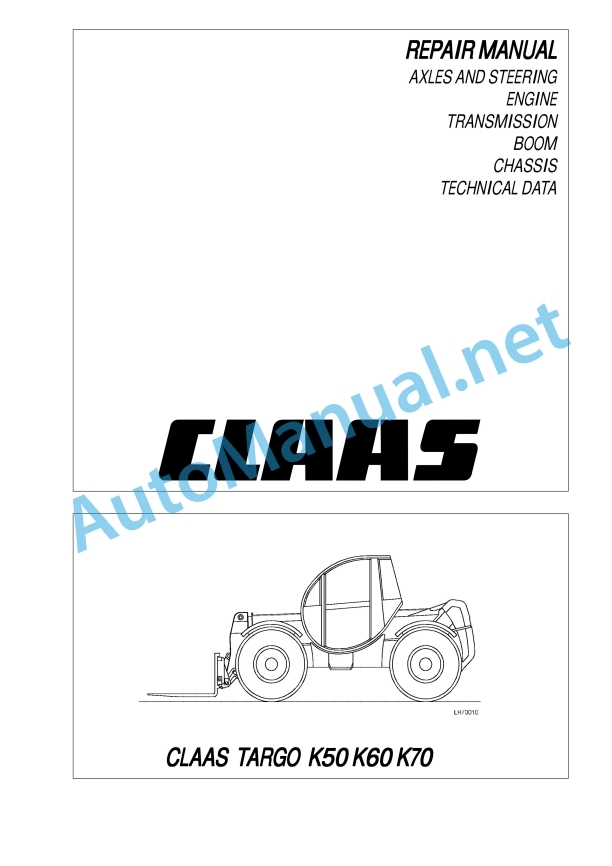
Claas Targo K70 (515) Telehandlers Technical System EN
$150.00
- Model: Targo K70 (515) Telehandlers
- Type Of Manual: Technical System
- Language: EN
- Format: PDF(s)
- Size: 36.7 MB
File List:
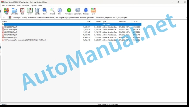
00 0298 657 0.pdf
00 0302 343 1.pdf
00 0302 565 2.pdf
00 0349 864 1.pdf
00 0349 865 0.pdf
CHP-numbers for connectors CLAAS HARNESS PARTS.pdf
00 0302 343 1.pdf:
PROFI CAM 3
Table of contents
General information
Marking of warnings and hazard prevention notes
First-aid measures
CCN explanation
CCN (CLAAS Component Number)
Electric system standard
Overview
Hydraulic system standard
Overview
CCN (CLAAS Component Number)
10 Electrical / Electronic equipment
1030 Board computer / Indicators
Camera system
Description of function
1097 Testing / Measuring / Adjusting
Testing / measuring / adjusting the PROFI CAM
Checking the fuse in the video channel select box (C102)
Testing the video camera connector (C055)
1098 Fault / remedy
Fault / remedy PROFI CAM
The video monitor (C101) shows no image or cannot be switched on (indicator light fails to light up)
Video monitor (C102) displays a blue image either permanently or temporarily
The video monitor image is blurred
Replacing the fuse in the video channel select box (C102)
Connection and connecting cable with video camera (C055)
00 0302 565 2.pdf:
Sensor system
Table of contents
CCN explanation
CCN (CLAAS Component Number)
Electric system standard
Overview
Hydraulic system standard
Overview
CCN (CLAAS Component Number)
Introduction
Safety rules
Safety and hazard information
10 Electrical / Electronic equipment
1097 Testing / Measuring / Adjusting
Test report of the angle sensor (0011780.x)
Application of test report
Required tools
Test report of the angle sensor (0011780.x)
Testing / Measuring / Adjusting of angle sensor (0011780.x)
1. Reason for test
2. Mechanical test of angle sensor
3. Electric test with CDS
4. Electric test with multimeter
5. Mechanical test of connecting cable
Completing the machine
Test report of position and speed sensors
Application of test report
Required tools
Sensor variants
Part numbers of speed sensors
Part number of position sensor
Test report of position and speed sensors
Testing / measuring / adjusting of position and speed sensors
1. Reason for test
2. Mechanical test
3. Electric test with CDS
4a. Installation dimensions
Check of installation dimension
Installation dimensions of gearbox speed sensor (0011 799.x) and cam speed sensor (0011 810.x)
Installation dimension of position sensor (0011 815.x)
4b. Installation position
Centring of sensor
Metal-free zone
5. Electric test with multimeter
Voltage measurement
Direction of rotation and speed sensor (0011 605.x)
Measured values table
6. Mechanical test of connecting cable
Completing the machine
Test report of the urea sensor (00 0773 207 x)
Application of test report
Required tools
Parts number of the urea sensor
Test report of the urea sensor
Testing / measuring / adjusting urea sensor
1. Reason for test
2. Mechanical test
3. Mechanical test of connecting cable
4. Electric test with multimeter
5. Component test with the CDS
00 0349 864 1.pdf:
00000001
00000002
00000003
00000004
00000005
00000006
00000007
00000008
00000009
00000010
00000011
00000012
00000013
00000014
00000015
00000016
00000017
00000018
00000019
00000020
00000021
00000022
00000023
00000024
00000025
00000026
00000027
00000028
00000029
00000030
00000031
00000032
00000033
00000034
00000035
00000036
00000037
00000038
00000039
00000040
00000041
00000042
00000043
00000044
00000045
00000046
00000047
00000048
00000049
00000050
00000051
00000052
00000053
00000054
00000055
00000056
00000057
00000058
00000059
00000060
00000061
00000062
00000063
00000064
00000065
00000066
00000067
00000068
00000069
00000070
00000071
00000072
00000073
00000074
00000075
00000076
00000077
00000078
00000079
00000080
00000081
00000082
00000083
00000084
00000085
00000086
00000087
00000088
00000089
00000090
00000091
00000092
00000093
00000094
00000095
00000096
00000097
00000098
00000099
00000100
00000101
00000102
00000103
00000104
00000105
00000106
00000107
00000108
00000109
00000110
00000111
00000112
00000113
00000114
00000115
00000116
00000117
00000118
00000119
00000120
00000121
00000122
00000123
00000124
00000125
00000126
00000127
00000128
00000129
00000130
00000131
00000132
00000133
00000134
00000135
00000136
00000137
00000138
00000139
00000140
00000141
00000142
00000143
00000144
00000145
00000146
00000147
00000148
00000149
00000150
00000151
00000152
00000153
00000154
00000155
00000156
00000157
00000158
00000159
leer.pdf
leer.pdf
leer.pdf
00 0349 865 0.pdf:
CONTENTS
INTRODUCTION
SAFETY WARNINGS
SECTION 1 AXLES AND STEERING
SECTION 2 ENGINE
SECTION 3 TRANSMISSION
SECTION 4 BOOM
SECTION 5 CHASSIS
SECTION 6 TECHNICAL DATA
CHP-numbers for connectors CLAAS HARNESS PARTS.pdf:
CLAAS HARNESS PARTS
Table of contents
10 Electrical / Electronic equipment
1081 Overview of connectors
CLAAS HARNESS PARTS (CHP)
John Deere Repair Technical Manual PDF
John Deere Repair Technical Manual PDF
John Deere Repair Technical Manual PDF
John Deere DF Series 150 and 250 Transmissions (ANALOG) Component Technical Manual CTM147 05JUN98
John Deere Repair Technical Manual PDF
John Deere Parts Catalog PDF
John Deere Tractors 7500 Parts Catalog CPCQ26568 30 Jan 02 Portuguese
John Deere Repair Technical Manual PDF
John Deere Repair Technical Manual PDF
John Deere Repair Technical Manual PDF

