Claas Torion 1511 (K57) Wheel Loaders Technical System EN
$150.00
- Model: Torion 1511 (K57) Wheel Loaders
- Type Of Manual: Technical System
- Language: EN
- Format: PDF(s)
- Size: 230 MB
File List:
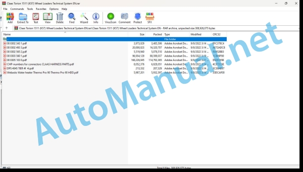
00 0302 343 1.pdf
00 0302 493 3.pdf
00 0302 565 2.pdf
00 0303 560 1.pdf
00 0305 103 0.pdf
CHP-numbers for connectors CLAAS HARNESS PARTS.pdf
DPS 4045 TIER 4f 4i.pdf
Webasto Water heater Thermo Pro 90 Thermo Pro 90 HDD.pdf
00 0302 343 1.pdf:
PROFI CAM 3
Table of contents
General information
Marking of warnings and hazard prevention notes
First-aid measures
CCN explanation
CCN (CLAAS Component Number)
Electric system standard
Overview
Hydraulic system standard
Overview
CCN (CLAAS Component Number)
10 Electrical / Electronic equipment
1030 Board computer / Indicators
Camera system
Description of function
1097 Testing / Measuring / Adjusting
Testing / measuring / adjusting the PROFI CAM
Checking the fuse in the video channel select box (C102)
Testing the video camera connector (C055)
1098 Fault / remedy
Fault / remedy PROFI CAM
The video monitor (C101) shows no image or cannot be switched on (indicator light fails to light up)
Video monitor (C102) displays a blue image either permanently or temporarily
The video monitor image is blurred
Replacing the fuse in the video channel select box (C102)
Connection and connecting cable with video camera (C055)
00 0302 493 3.pdf:
TORION 1177TORION 1410TORION 1511
Table of contents
Introduction
Validity of manual
Validity of manual
General information
Marking of warnings and hazard prevention notes
Safety routines
First-aid measures
CCN explanation
CCN (CLAAS Component Number)
Electric systems standard
Overview
Hydraulic system standard
Overview
CCN (CLAAS Component Number)
01 Engine
0135 Cooling system
Variable cooling fan
Without fan reversing
With fan reversing
Measured values table
Description of function
0150 Engine attachment parts
Starting the diesel engine, accelerator pedal, fuel sensor
Measured values table
Description of function
0155 Engine control
Electronic Engine Control
0165 Exhaust gas aftertreatment
Exhaust gas treatment
0197 Test/Measurement/Setting
Engine and cooling test protocol
Important notes and preparation
Test protocol type K55
Test protocol type K56
Test protocol type K57
Testing and adjusting the cooling system hydraulics
Testing the fan solenoid valve
Maximum operating pressure
Checking the pressure limitation upon failure of fan solenoid valve
03 Chassis
0335 Ground drive
Ground drive
Description of function
Drive pump
Description of function
Drive motor 1
Description of function
Drive motor 2
Description of function
0397 Testing / measuring / adjusting
Ground drive test protocol
Important notes and preparation
Test protocol type K55
Test protocol type K56 / K57
Testing and adjusting the ground drive
Adjusting the pedals
Adjusting the clutch
Adjusting the clutch quick draining phase
Testing and adjusting the drive pump
Checking the charge pressure limiting valve
Testing the high pressure limiting valves
Testing the pressure cut-off
Testing the deviation of the drive pump pressure sensor
Automatic ground drive pump block curve adjustment
Manual drive pump block curve adjustment
Testing drive motor 1
Testing the start of regulation
Testing drive motor 2
Automatic adjustment
Testing the ground drive performance
04 Brake
0400 Brake
Brake system
Measured values table
Description of function
0497 Testing / measuring / adjusting
Brake system test protocol
Important notes and preparation
Test protocol
Testing and adjusting the brake system
05 Steering
0505 Steering
Steering system with emergency steering
Description of function
Joystick steering
Description of function
0597 Testing / measuring / adjusting
Steering system test protocol
Important notes and preparation
Test protocol type K55
Test protocol type K56 / K57
Testing and adjusting the steering system
Standard steering system
LS pressure cut-off
Testing the steering dampening hydraulic accumulator
Joystick steering
Joystick steering: determining the installation position of position sensors
Adjusting the articulated joint sensor
Adjusting the joystick steering main spool
Adjusting the joystick steering emergency spool
Adjusting the start of steering system movement
06 Lift device
0630 Lift arms
Working attachment
Measured values table
Table of measured values of TORION 1177 / K55 3rd and 4th control circuit
Table of measured values of TORION 1410 / K56 and TORION 1511 / K57 3rd and 4th control circuit
Description of function
0697 Testing / measuring / adjusting
Working hydraulics test protocol
Important notes and preparation
Test protocol type K55
Test protocol type K56 / K57
Testing and adjusting the working hydraulics
Adjusting the multi-lever control unit (option)
Adjusting the lift arms angle sensors (option)
Testing and adjusting the working hydraulics pump
Flow rate controller
Working hydraulics control block
Adjusting the proportional valves
Manual adjustment of proportional valves for lift and tipping functions
Manual adjustment of proportional valves for 3rd and 4th function
Secondary pressure relief valves
LS pressure cut-off
Stabilisation module
Testing the shut-off function
Testing the pitching dampening hydraulic accumulator
Quick-hitch plate
Testing the pressure reduction valve
09 Hydraulic system
0910 Pumps
Working hydraulics pump
Description of function
0920 Valves
Working hydraulics control block
Description of function
Working hydraulics pilot control solenoid valve
Description of function
Stabilisation module
Description of function
Fan reversing valve block
Orbitrol steering unit
Description of function
Dynamic steering
Description of function
Joystick steering control block, up to K5500080 / K5600075 / K5700096
Description of function
Joystick steering control block, from K5500081 / K5600076 / K5700097
Description of function
Compact brake valve
Description of function
0980 Hydraulic circuit diagram
Cooling system hydraulic circuit diagram
Cooling system without reversing fan
Cooling system with reversing fan
Ground drive hydraulics hydraulic circuit diagram
Brake hydraulic circuit diagram
Steering hydraulic circuit diagram
Joystick steering hydraulic circuit diagram, up to K5500080 / K5600075 / K5700096
Joystick steering hydraulic circuit diagram, from K5500081 / K5600076 / K5700097
P linkage working hydraulics circuit diagram
Z linkage working hydraulics circuit diagram
Pipe break protection device hydraulic circuit diagram
0997 Testing / measuring / adjusting
Testing the hydraulic accumulator nitrogen filling
10 Electrical / Electronic equipment
1005 Power supply
Earth points
1010 Central electrics
Cab main board – A4-LBH
Key to diagram
Fuse assignment
Relay assignment
1012 Modules / sensors
Module A11-LBH – Main keyboard
Key to diagram
Key to diagram
Module A13-LBH – Display unit
Key to diagram
Key to diagram
Module A15-LBH – Master control unit master 5
Key to diagram
Key to diagram
Module A16M-LBH – Multi-lever control unit input module
Key to diagram
Key to diagram
Module A21-LBH – Heater / air conditioner
Key to diagram
Key to diagram
Module A23-LBH – Weighing unit control unit
Key to diagram
Key to diagram
Module A26-LBH – Pilot sensor
Key to diagram
Key to diagram
Module A27-LBH – Compact module 1
Key to diagram
Key to diagram
Module types of compact modules
Addresses of compact modules
Module A28-LBH – Compact module 2
Key to diagram
Key to diagram
Module types of compact modules
Addresses of compact modules
Module A29-LBH – Joystick steering
Key to diagram
Key to diagram
1040 Yield measuring
Weighing unit
Description of function
Weighing unit control unit
Pressure sensor
Proximity switch
Weighing system proximity switch (lift arms)
Weighing system proximity switch (tipping cylinder)
1080 Electrical circuit diagram
Introduction into electric circuit diagrams
Electric circuit diagrams of machine (SCM)
SCM 20 – Ignition switch
Key to diagram
SCM 21 – Battery, master switch, electric starting motor
Key to diagram
SCM 22 – Alternator, hour meter
Key to diagram
SCM 23 – Lighting
Key to diagram
SCM 24 – Turn signal indicator actuation
Key to diagram
SCM 25 – Numberplate lighting, outline lights
Key to diagram
SCM 26 – Front work light
Key to diagram
SCM 27 – Rear work light
Key to diagram
SCM 28 – Front and rear additional lights
Key to diagram
SCM 29 – Front windscreen wiper
Key to diagram
SCM 30 – Rear windscreen wiper
Key to diagram
SCM 31 – Interior lighting, broadcast receiver, driver’s seat
Key to diagram
SCM 32 – Rear window heater, mirror heater
Key to diagram
SCM 33 – Warning beacon
Key to diagram
SCM 34 – Accelerator pedal, inching pedal
Key to diagram
SCM 35 – Drive range
Key to diagram
SCM 36 – Ground drive outputs
Key to diagram
SCM 37 – Buzzer, valves
Key to diagram
SCM 38 – Working hydraulics valves
Key to diagram
SCM 39 – Fan valves
Key to diagram
SCM 40 – Temperature, speed and pressure sensor
Key to diagram
SCM 41 – Lift arms inductive switch
Key to diagram
SCM 42 – Emergency steering pump actuation
Key to diagram
SCM 43 – Diesel particulate filter regeneration
Key to diagram
SCM 44 – Display and rear view camera
Key to diagram
SCM 46 – Spare fuses
Key to diagram
SCM 47 – Spare inputs
Key to diagram
SCM 49 – CAN 1 wiring
Key to diagram
SCM 50 – CAN 2 wiring
Key to diagram
SCM 51 – CAN 3 wiring
Key to diagram
SCM 52 – CAN 4 wiring
Key to diagram
SCM 53 – Master power supply
Key to diagram
SCM 54 – Compact module 1 (1) power supply
Key to diagram
SCM 55 – Compact module 1 (2) power supply
Key to diagram
SCM 56 – Compact module 2 (1) power supply
Key to diagram
SCM 57 – Compact module 2 (2) power supply
Key to diagram
SCM 64 – Quick-hitch plate option
Key to diagram
SCM 65 – Lift arms angle sensor option
Key to diagram
SCM 66 – Acoustic back-up warning system option
Key to diagram
SCM 67 – Central lubrication system option
Key to diagram
SCM 68 – Back-up warning system option
Key to diagram
SCM 69 – Differential lock option
Key to diagram
SCM 70 – Country-specific version option
Key to diagram
SCM 71 – Dust filter overpressure system option
Key to diagram
SCM 72 – Horn actuation by pushbutton and additional pushbutton option
Key to diagram
SCM 73 – Immobiliser option
Key to diagram
SCM 74 – Back-up obstacle sensor
Key to diagram
SCM 75 – Additional heater option
Key to diagram
SCM 76 – Weighing unit 1 option
Key to diagram
SCM 78 – Weighing unit 2 option
Key to diagram
SCM 80 – Road sweeper option
Key to diagram
SCM 82 – Safety belt option
Key to diagram
SCM 83 – 3-point safety belt option
Key to diagram
SCM 84 – Mirror adjustment option
Key to diagram
SCM 85 – Dynamic steering option
Key to diagram
SCM 86 – Likufix option
Key to diagram
SCM 90 – OBD diagnostic plug and telemetry system
Key to diagram
SCM 92 – Diesel fuel pre-heating option
Key to diagram
SCM 93 – Refuelling pump option
Key to diagram
SCM 94 – Cooling water pre-heating option
Key to diagram
SCM 95 – Jump leads 24 V option
Key to diagram
SCM 98 – Joystick steering 1 option
Key to diagram
SCM 99 – Joystick steering 2 option
Key to diagram
SCM 100 – Joystick steering 3 option
Key to diagram
SCM 101 – Joystick steering 4 option
Key to diagram
SCM 102 – Joystick steering 5 option
Key to diagram
SCM 103 – Joystick steering 6 option
Key to diagram
SCM 104 – Joystick steering 7 option
Key to diagram
SCM 107 – Multi-lever control unit 1 option
Key to diagram
SCM 108 – Multi-lever control unit 2 option
Key to diagram
SCM 109 – Multi-lever control unit 3 option
Key to diagram
SCM 110 – Multi-lever control unit 4 option
Key to diagram
SCM 111 – Multi-lever control unit 5 option
Key to diagram
SCM 112 – Multi-lever control unit 7 option
Key to diagram
SCM 113 – Multi-lever control unit 8 option
Key to diagram
SCM 114 – Multi-lever control unit 9 option
Key to diagram
SCM 115 – Multi-lever control unit 10 option
Key to diagram
SCM 118 – Heater and air conditioner (device side)
Key to diagram
SCM 121 – Heater and air conditioner 1 (system side)
Key to diagram
SCM 122 – Heater and air conditioner 2 (system side)
Key to diagram
SCM 123 – Heater and air conditioner 3 (system side)
Key to diagram
SCM 124 – Heater and air conditioner 4 (system side)
Key to diagram
SCM 127 – Engine control unit power supply (1)
Key to diagram
SCM 128 – Engine control unit power supply (2)
Key to diagram
SCM 130 – Motor 1 (device side)
Key to diagram
SCM 131 – Motor 2 (device side)
Key to diagram
SCM 132 – Motor 3 (device side)
Key to diagram
SCM 133 – Motor 4 (device side)
Key to diagram
SCM 134 – Motor 5 (device side)
Key to diagram
SCM 137 – Engine 1 (engine side)
Key to diagram
SCM 138 – Engine 2 (engine side)
Key to diagram
SCM 139 – Engine 3 (engine side)
Key to diagram
SCM 140 – Engine 4 (engine side)
Key to diagram
SCM 141 – Engine 5 (engine side)
Key to diagram
SCM 142 – Engine 6 (engine side)
Key to diagram
SCM 144 – Delayed automatic shut-off option
Key to diagram
1085 Networks
CAN-BUS and Ethernet
Description of function
12 Cab / Operator’s platform
1240 Air condition
Heater, ventilation, automatic air conditioner
Measured values table
Description of function
75 Central lubrication system
7505 Reservoir / Pump
Central lubrication system
Description of function
7515 Lubrication system / Lines
Grease distribution
Z linkage grease distribution
P linkage grease distribution
Position of components
Hydraulic system
1001-1999 Oil tank / filter / cooler
2001-2999 Pump / motor
3001-3999 Hydraulic cylinders
4000 Restrictor / orifice plate
5001-5999 Accumulator
6001-6999 Valves – mechanically actuated (hydraulic system)
7001-7999 Valves – hydraulically actuated
8001-8999 Couplings / connections
9001-9999 Measuring points / gauges
Electric system
A Terminal / modules
B Sensors
E Lighting
G Voltage sources
H Signal device / light
S Switch / pushbutton – Cab operation
T Voltage transformer
X Connectors
Y Solenoid coils
00 0302 565 2.pdf:
Sensor system
Table of contents
CCN explanation
CCN (CLAAS Component Number)
Electric system standard
Overview
Hydraulic system standard
Overview
CCN (CLAAS Component Number)
Introduction
Safety rules
Safety and hazard information
10 Electrical / Electronic equipment
1097 Testing / Measuring / Adjusting
Test report of the angle sensor (0011780.x)
Application of test report
Required tools
Test report of the angle sensor (0011780.x)
Testing / Measuring / Adjusting of angle sensor (0011780.x)
1. Reason for test
2. Mechanical test of angle sensor
3. Electric test with CDS
4. Electric test with multimeter
5. Mechanical test of connecting cable
Completing the machine
Test report of position and speed sensors
Application of test report
Required tools
Sensor variants
Part numbers of speed sensors
Part number of position sensor
Test report of position and speed sensors
Testing / measuring / adjusting of position and speed sensors
1. Reason for test
2. Mechanical test
3. Electric test with CDS
4a. Installation dimensions
Check of installation dimension
Installation dimensions of gearbox speed sensor (0011 799.x) and cam speed sensor (0011 810.x)
Installation dimension of position sensor (0011 815.x)
4b. Installation position
Centring of sensor
Metal-free zone
5. Electric test with multimeter
Voltage measurement
Direction of rotation and speed sensor (0011 605.x)
Measured values table
6. Mechanical test of connecting cable
Completing the machine
Test report of the urea sensor (00 0773 207 x)
Application of test report
Required tools
Parts number of the urea sensor
Test report of the urea sensor
Testing / measuring / adjusting urea sensor
1. Reason for test
2. Mechanical test
3. Mechanical test of connecting cable
4. Electric test with multimeter
5. Component test with the CDS
00 0305 103 0.pdf:
TORION 1177TORION 1410TORION 1511
Table of contents
Introduction
Validity of manual
Validity of manual
General information
Marking of warnings and hazard prevention notes
Safety routines
First-aid measures
CCN explanation
CCN (CLAAS Component Number)
Electric systems standard
Overview
Hydraulic system standard
Overview
CCN (CLAAS Component Number)
01 Engine
0135 Cooling system
Variable cooling fan
Without fan reversing
With fan reversing
Measured values table
Description of function
0150 Engine attachment parts
Starting the diesel engine, accelerator pedal, fuel sensor
Measured values table
Description of function
Overview of electric components on the diesel engine
Validity: type K55 / K56
Validity: type K57
0155 Engine control
Electronic Engine Control
0165 Exhaust gas aftertreatment
Exhaust gas treatment
0197 Test/Measurement/Setting
Engine and cooling test protocol
Important notes and preparation
Test protocol type K55
Test protocol type K56
Test protocol type K57
Testing and adjusting the cooling system hydraulics
Testing the fan solenoid valve
Maximum operating pressure
Checking the pressure limitation upon failure of fan solenoid valve
03 Chassis
0335 Ground drive
Ground drive
Description of function
Drive pump
Description of function
Drive motor 1
Description of function
Drive motor 2
Description of function
0397 Testing / measuring / adjusting
Ground drive test protocol
Important notes and preparation
Test protocol type K55
Test protocol type K56
Test protocol type K57
Testing and adjusting the ground drive
Adjusting the pedals
Adjusting the clutch
Adjusting the clutch quick draining phase
Testing and adjusting the drive pump
Checking the charge pressure limiting valve
Testing the high pressure limiting valves
Testing the pressure cut-off
Testing the deviation of the drive pump pressure sensor
Automatic ground drive pump block curve adjustment
Manual drive pump block curve adjustment
Testing drive motor 1
Testing the start of regulation
Testing drive motor 2
Automatic adjustment
Testing the ground drive performance
04 Brake
0400 Brake
Brake system
Measured values table
Description of function
0497 Testing / measuring / adjusting
Brake system test protocol
Important notes and preparation
Test protocol
Testing and adjusting the brake system
05 Steering
0505 Steering
Steering system with emergency steering
Description of function
Joystick steering
Description of function
Reactive joystick steering
Dynamic steering
Measured values table
Description of function
0597 Testing / measuring / adjusting
Steering system test protocol
Important notes and preparation
Test protocol type K55
Test protocol type K56 / K57
Testing and adjusting the steering system
Standard steering system
LS pressure cut-off
Testing the steering dampening hydraulic accumulator
Joystick steering
Joystick steering: determining the installation position of position sensors
Adjusting the joystick for joystick steering
Adjusting the articulated joint sensor
Adjusting the joystick steering main spool
Adjusting the joystick steering emergency spool
Adjusting the start of steering system movement
06 Lift device
0630 Lift arms
Working attachment
Measured values table
Table of measured values of TORION 1177 / K55 3rd and 4th control circuit
Table of measured values of TORION 1410 / K56 and TORION 1511 / K57 3rd and 4th control circuit
Description of function
0697 Testing / measuring / adjusting
Working hydraulics test protocol
Important notes and preparation
Test protocol type K55
Test protocol type K56 / K57
Testing and adjusting the working hydraulics
Adjusting the multi-lever control unit (option)
Adjusting the lift arms angle sensors
Testing and adjusting the working hydraulics pump
Flow rate controller
Working hydraulics control block
Adjusting the proportional valves
Manual adjustment of proportional valves for lift and tipping functions
Manual adjustment of proportional valves for 3rd and 4th function
Secondary pressure relief valves
LS pressure cut-off
Stabilisation module
Testing the shut-off function
Testing the pitching dampening hydraulic accumulator
Quick-hitch plate
Testing the pressure reduction valve
09 Hydraulic system
0910 Pumps
Working hydraulics pump
Description of function
0920 Valves
Working hydraulics control block
Description of function
Working hydraulics pilot control solenoid valve
Description of function
Stabilisation module
Description of function
Orbitrol steering unit
Description of function
Dynamic steering
Description of function
Joystick steering control block, from K5500081 / K5600076 / K5700097
Description of function
Compact brake valve
Description of function
0980 Hydraulic circuit diagram
Cooling system hydraulic circuit diagram
Cooling system without reversing fan
Cooling system with reversing fan
Ground drive hydraulics hydraulic circuit diagram
Brake hydraulic circuit diagram
TORION type K55 / K56
TORION type K57
Steering hydraulic circuit diagram
Joystick steering hydraulic circuit diagram, from K5500081 / K5600076 / K5700097
P linkage working hydraulics circuit diagram
Z linkage working hydraulics circuit diagram
Pipe break protection device hydraulic circuit diagram
0997 Testing / measuring / adjusting
Testing the hydraulic accumulator nitrogen filling
10 Electrical / Electronic equipment
1005 Power supply
Earth points
1010 Central electrics
Cab main board – A4-LBH
Key to diagram
Fuse assignment
Relay assignment
1012 Modules / sensors
Module A11-LBH – Main keyboard
Key to diagram
Key to diagram
Module A13-LBH – Display unit
Key to diagram
Key to diagram
Module A15-LBH – Master control unit master 5
Key to diagram
Key to diagram
Module A16M-LBH – Multi-lever control unit input module
Key to diagram
Key to diagram
Signal types of input modules
Addresses of input modules
Module A21-LBH – Heater / air conditioner
Key to diagram
Key to diagram
Module A27-LBH – Compact module 1
Key to diagram
Key to diagram
Module types of compact modules
Addresses of compact modules
Module A28-LBH – Compact module 2
Key to diagram
Key to diagram
Module types of compact modules
Addresses of compact modules
Module A29-LBH – Joystick steering
Key to diagram
Key to diagram
Module A35-LBH – Additional control unit
Key to diagram
Key to diagram
Address of additional control unit
Description of function
1025 Working lights
Adaptive work lights
Measured values table
Description of function
1040 Yield measuring
Weighing unit
Measured values table
Description of function
1080 Electrical circuit diagram
Introduction into electric circuit diagrams
Electric circuit diagrams of machine (SCM)
SCM 23 – Ignition switch
Key to diagram
SCM 24 – Battery, master switch, electric starting motor
Key to diagram
SCM 25 – Alternator, hour meter
Key to diagram
SCM 26 – Front lighting
Key to diagram
SCM 27 – Rear lighting
Key to diagram
SCM 28 – Turn signal indicator actuation
Key to diagram
SCM 29 – Numberplate lighting, outline lights
Key to diagram
SCM 30 – Front work light
Key to diagram
SCM 31 – Rear work light
Key to diagram
SCM 32 – Front and rear additional lights
Key to diagram
SCM 33 – Front windscreen wiper, horn
Key to diagram
SCM 34 – Rear windscreen wiper
Key to diagram
SCM 35 – Interior lighting, broadcast receiver, driver’s seat
Key to diagram
SCM 36 – Rear window heater, mirror heater
Key to diagram
SCM 37 – Warning beacon
Key to diagram
SCM 38 – Accelerator pedal, inching pedal
Key to diagram
SCM 39 – Drive range
Key to diagram
SCM 40 – Ground drive outputs
Key to diagram
SCM 41 – Buzzer, valves
Key to diagram
SCM 42 – Working hydraulics valves
Key to diagram
SCM 43 – Fan valves
Key to diagram
SCM 44 – Temperature, speed and pressure sensor
Key to diagram
SCM 45 – Emergency steering pump actuation
Key to diagram
SCM 46 – Diesel particulate filter regeneration
Key to diagram
SCM 47 – Display and rear view camera
Key to diagram
SCM 48 – Ethernet diagnostic plug
Key to diagram
SCM 49 – Telemetric system
Key to diagram
SCM 50 – Spare fuses
Key to diagram
SCM 52- CAN 1 wiring
Key to diagram
SCM 53 – CAN 2 wiring, pilot sensor with mini joystick
Key to diagram
SCM 54 – CAN 2 wiring, pilot sensor without mini joystick
Key to diagram
SCM 55 – Mini joystick pilot sensor lever
Key to diagram
SCM 56 – CAN 3 wiring
Key to diagram
SCM 57 – CAN 4 wiring
Key to diagram
SCM 58 – Master power supply
Key to diagram
SCM 59 – Compact module 1 (1) power supply
Key to diagram
SCM 60 – Compact module 1 (2) power supply
Key to diagram
SCM 61 – Compact module 2 (1) power supply
Key to diagram
SCM 62 – Compact module 2 (2) power supply
Key to diagram
SCM 68 – Lift arms rotary encoder
Key to diagram
SCM 70 – Heater and air conditioner (device side)
Key to diagram
SCM 73 – Heater and air conditioner (system side)
Key to diagram
SCM 74 – Engine control unit power supply
Key to diagram
SCM 75 – Engine control unit power supply
Key to diagram
SCM 76 – Diesel engine spare fuse
Key to diagram
SCM 77 – Quick-hitch plate option
Key to diagram
SCM 78 – Acoustic back-up warning system option
Key to diagram
SCM 79 – Central lubrication system option
Key to diagram
SCM 80 – Back-up warning system option
Key to diagram
SCM 81 – Differential lock option
Key to diagram
SCM 82 – Country-specific version option
Key to diagram
SCM 83 – Dust filter overpressure system option
Key to diagram
SCM 84 – Horn actuation by pushbutton option
Key to diagram
SCM 85 – Immobiliser option
Key to diagram
SCM 86 – Back-up obstacle sensor
Key to diagram
SCM 87 – Additional heater option
Key to diagram
SCM 88 – Weighing unit option
Key to diagram
SCM 89 – Road sweeper option
Key to diagram
SCM 91 – Safety belt, warning beacon option
Key to diagram
SCM 92 – 3-point safety belt option
Key to diagram
SCM 93 – Mirror adjustment option
Key to diagram
SCM 94 – Dynamic steering option
Key to diagram
SCM 95 – Lighting control option
Key to diagram
SCM 96 – Lighting control 2 option
Key to diagram
SCM 97 – Lighting control 3
Key to diagram
SCM 98 – OBD diagnostic plug and telemetry system
Key to diagram
SCM 100 – Diesel fuel pre-heating option
Key to diagram
SCM 101 – Refuelling pump option
Key to diagram
SCM 102 – Cooling water pre-heating option
Key to diagram
SCM 103 – Jump leads 24 V option
Key to diagram
SCM 106 – Joystick steering CAN BUS option
Key to diagram
SCM 107 – Joystick steering power supply option
Key to diagram
SCM 108 – Joystick steering sensors I option
Key to diagram
SCM 109 – Relay circuit, power supply and arm rest with joystick steering option
Key to diagram
SCM 110 – Joystick steering sensors II option
Key to diagram
SCM 111 – Joystick steering option safety circuit including dynamic steering
Key to diagram
SCM 112 – Joystick steering valves option
Key to diagram
SCM 113 – Delayed automatic shut-off option
Key to diagram
SCM 114 – Cooling box option
Key to diagram
SCM 115 – LED drive lights option
Key to diagram
SCM 118 – Multi-lever control unit input module M option
Key to diagram
SCM 119 – Multi-lever control unit option
Key to diagram
SCM 120 – Multi-lever control unit option
Key to diagram
SCM 121 – Direction of travel multi-lever control unit option
Key to diagram
SCM 122 – Start switch multi-lever control unit option
John Deere Repair Technical Manual PDF
John Deere Repair Technical Manual PDF
John Deere Application List Component Technical Manual CTM106819 24AUG20
John Deere Repair Technical Manual PDF
John Deere Repair Technical Manual PDF
John Deere Repair Technical Manual PDF
John Deere Parts Catalog PDF
John Deere Tractors 6300, 6500, and 6600 Parts Catalog CQ26564 (29SET05) Portuguese
John Deere Parts Catalog PDF
John Deere Tractors 7500 Parts Catalog CPCQ26568 30 Jan 02 Portuguese
John Deere Repair Technical Manual PDF
John Deere Repair Technical Manual PDF

